Defender (1993+). Manual - part 97
AIR CONDITIONING
26.
Release the nuts and remove the bracket from
expansion valve and high pressure pipe
underneath the evaporator casing.
Place valve on bench and unscrew the high
27. Remove the wire
clip
and detach the dump
pressure pipe from the expansion valve.
valve located underneath.
46. Seal and cap all apertures; discard all ' O '
28.
Release the seven self tapping screws
rings which are renewed on assembly.
securing the outlet duct and carefully break
the sealing compound around the edge of the
duct and pull ducting plate away from
evaporator body.
47. Reverse procedures 11 to 46 noting that all
29. Remove the fifteen screws located around the
threads, unions, ' O ' rings are coated
with
cover
seam.
Remove the old sealing
refrigerant oil prior to fitting.
compound from the body and top cover.
the top of the cover.
screws adjacent to the low pressure pipe
Evaporator Matrix or Expansion Valve 6 to 10
moulding.
and then charge the air conditioning system as
32. At the side of the unit remove the two screws
previously described with Refrigerant 12.
adjacent to the air intake aperture.
33. Lift the top cover off whilst feeding the blower
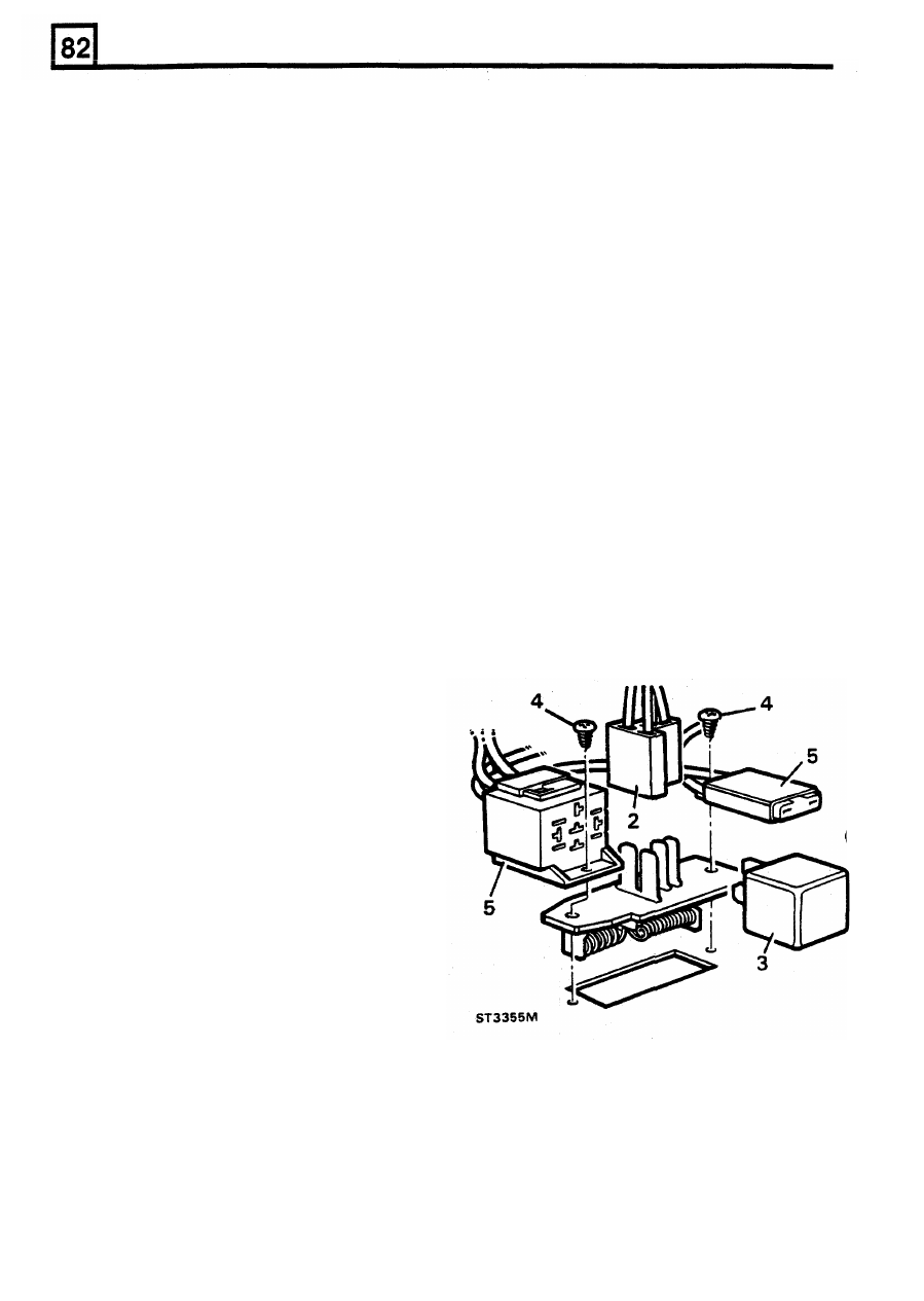
RESISTOR BLOCK
motor wiring and air control flap rod through
their respective apertures, thus exposing the
Removal
blower
motor,
heater
matrix
and
air
conditioning evaporator matrix.
1.
Disconnect the battery.
Refitting
30. Remove the four screws and four nuts from
NOTE: Depending
upon
which unit has been
31.
From the front of the unit remove the
two
Heater Matrix or Blower Motor
3
to
5
refitted reverse the appropriate procedures:
2.
Detach the electrical connector from the.
resistor block.
3. Withdraw the relay module from it's socket.
socket, fuse holder and resistor block.
Blower motor unit removal only
34.
Remove the screws retaining the motor unit to
4. Remove the screws securing relay module
the casing.
35.
Release the three bracket retaining screws
5.
Move fuse holder and relay module socket
and withdraw motor and impeller.
aside and lift resistor block clear of the
36. Detach the star washer. spring clip and
evaporator.
impeller.
37. Remove the two nuts from the motor shroud
and lift clear.
Heater/Evaporator matrices removal only
38.
Lift the support plate and insulation pad from
the matrix.
three screws adjacent to the dump valve
outlet, in addition
to
the screws next to the
heater pipes.
40. Lift the evaporator and heater matrices
together with the supporting frame containing
the air direction flap clear
of
the casing.
41. Detach the evaporator matrix by releasing the
four screws, two at
both
ends of the support
bracket.
42. Detach the heater matrix
by
removing the
self-tapping screw.
39. From the bottom
of
the casing, remove the
Refitting
Expansion valve removal
6.
To
refit the resistor block, reverse the removal
43. Support the suction pipe union with suitable
procedure.
spanners and release.
44. Remove the bleed pipe retaining nut from the
suction pipe.
45. Remove the
spring clip
retaining the
expansion valve sensor pipe to the main
suction
pipe which
now
releases the
22
REISSUED: FEB 1993