Defender (1993+). Manual - part 84


  Index      Land Rover     Defender - service manual 1993 year


Search            


Content   ..  82  83  84  85   ..


Defender (1993+). Manual - part 84


BRAKING 

SYSTEM 

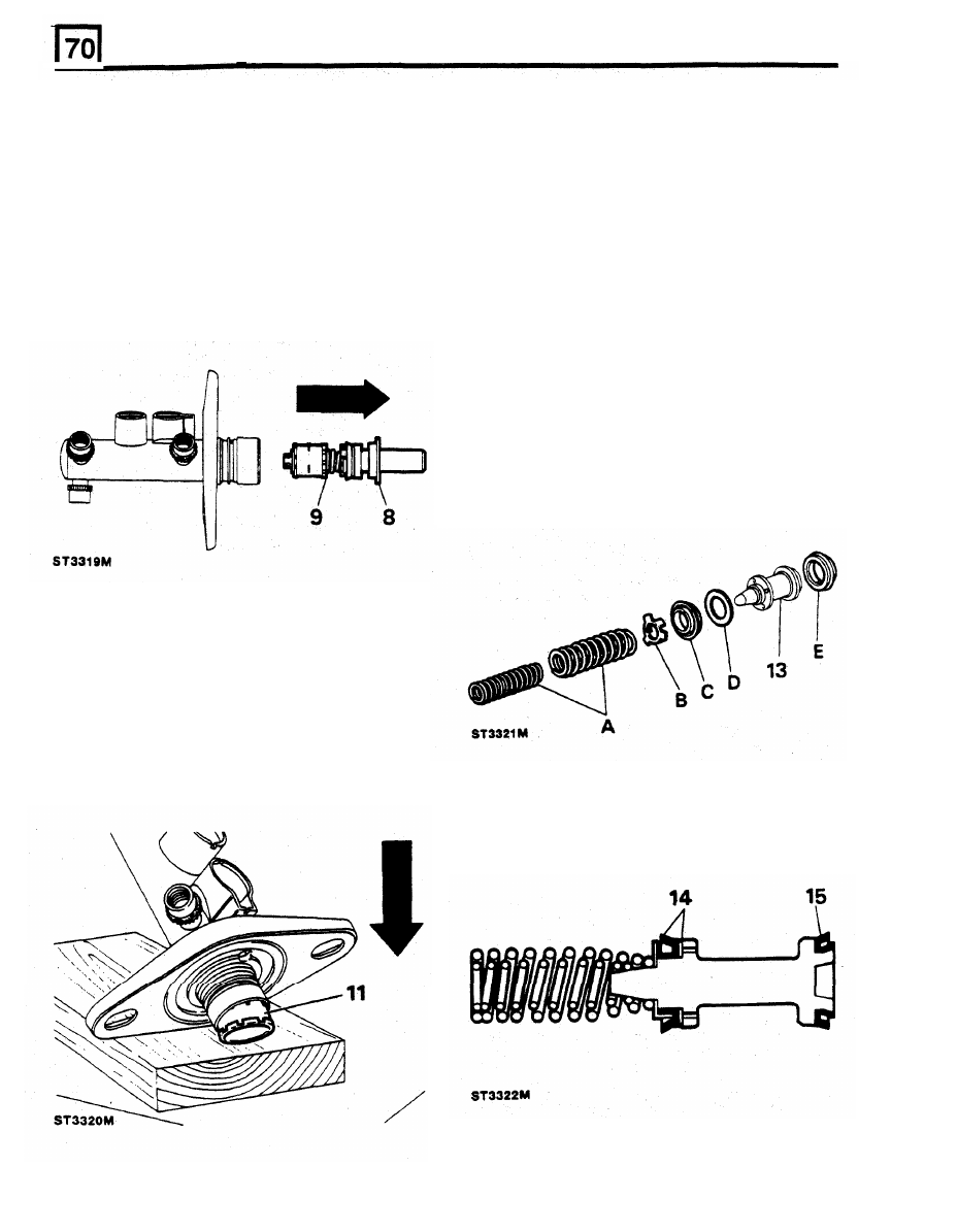
8.  Remove the  guide  ring from  the  mouth of  the 

12. 

Clean  all  parts  with  Girling  cleaning  fluid  or 

master  cylinder  which  supports  the  primary 

unused  brake  fluid  and  place  the  cleaned 

plunger  assembly  and  place to  one  side,  this 

parts on to a clean sheet of  paper. Inspect the 

component  is  not  part 

of 

the  master  cylinder 

cylinder  bore  and  plungers  for  signs  of 

service kit and is to  be refitted on assembly of 

corrosion,  ridges  and  score  marks.  Provided 

the  unit. 

the  working  surfaces  are  in  perfect condition, 

9.  Pull  the  primary  plunger  assembly 

out 

of  the 

new  seals  from  a  Girling  Service  repair  kit 

master cylinder. 

may be used. 

NOTE: 

The  primary plunger  assembly cannot 

be 

broken  down  any  further  and  is  serviced  as  a 
complete unit. Discard 
the assembly. 

Renewing secondary plunger seals 

secondary plunger and discard: 

13. 

Remove  the  following  components  from  the 

NOTE: A 

small  screwdriver with  the end  rounded 

and  polished  is  required to  remove the 

'L' 

seal. 

DO 

NOT 

damage the secondary plunger. 

A. 

Springs 

B.  Seal retainer 

C. 

Recuperating seal (primary cup) 

D. 

Washer 

E.  'L' 

seal 

10. 

The  secondary  plunger  assembly  will  remain 
at  the  bottom of  the  master cylinder  bore, the 
plunger  can  be easily  expelled by  tapping the 
assembly  on 

piece 

of 

timber  until  the 

plunger  appears  at  the  cylinder  mouth, 

carefully  pull  the  plunger 

out 

of  the  master 

cylinder. 

11. 

If 

the swirl  tube was  not expelled at  the same 

time  as  the  secondary  plunger,  repeat  the 
above operation 

to 

expel it from the  bottom of 

the master cylinder bore and discard. 

14. 

Coat the  new  seals  in unused brake fluid  and 
firstly fit the 'L' seal to the plunger. 

15. 

Fit  the  washer  followed  by  the  recuperating 

seal.  Fit  the  seal retainer and springs,  ensure 
the springs are correctly seated. 

BRAKING SYSTEM 

RENEW  BRAKE  MASTER  CYLINDER  -  Lucas 

Fitting new master cylinder 

Girling type 25,4  mm AS/AS 

Removing 

9. 

Insert  new  reservoir  seals  in  the  master 

cylinder ports and fit  the  reservoir by reversing 
the removal method. 

1. 

Disconnect the battery. 

10. 

Ensure  that  the  water  ingress  seal  is  in 

2. 

Place a container  under the  master cylinder  to 

position  between  master  cylinder  flange  and 

catch escaping brake fluid. 

servo  and  fit  master  cylinder  to  servo  and 

3.  Clean area round master cylinder  ports. 

secure  with  the  two  nuts  tightening  evenly 

to 

4. 

Disconnect  the  pipes  from  master  cylinder 

the correct torque 

11 

to 

17 

Nm. 

ports.  Cover,  not  plug,  the  pipe  ends  to 
prevent entry 

of 

dirt. 

5. 

Disconnect electrical leads from  reservoir cap. 

6. 

Remove the two  nuts  securing  master cylinder 

to 

servo and withdraw cylinder. 

7 .   Remove  reservoir  cap  and  drain  fluid  into 

container for  disposal. 

WARNING: 

Do 

not use fluid drained or  bled from 

the  system.  Dispose 

of 

fluid  as  instructed  in 

SECTION 

01 

in  a  container  marked 

"Used 

brake 

fluid". 

11. 

Connect  the  brake  pipes  to  the  master 
cylinder ports and tighten to 16 Nm. 

12. 

Fill the reservoir with the Correct grade 

of 

new 

fluid,  see 

SECTION 

09, taken 

from  a 

sealed 

container. 

13.  BIeed the brake system. 
14. 

Connect the battery and road test  vehicle. 

8 .   The  reservoir  is  a  push  fit  in  the  master 

cylinder  and secured 

by 

seals.  Carefully ease 

the  reservoir  from  the  master  cylinder  by 

rolling  it  from  the  seals,  as  illustrated  in 
Master  Cylinder  Overhaul.  Note  that  the  two 
seals are different in size. 

BRAKING SYSTEM 

RENEW 'G' VALVE - where fitted 

The 

'G' 

valve  on  both right-hand and left-hand drive 

vehicles  is  situated  on  the  right-hand  side 

of 

the 

chassis, within  the  engine  compartment,  attached to 

1. 

Disconnect  the  brake  vacuum  hose  from  the 

a  bracket,  at  the  commencement  of  the  front  axle 

servo non return valve. 

arch. 

2. 

The  valve  is  a  push  fit  in  the  servo  and  to 
remove  it,  carefully  prise the  valve  out  with 

Removing 

screwdriver  blade  between  the  valve  and 
grommet.  Take  care  not 

to 

exert 

too 

much 

1. 

Disconnect the battery. 

pressure on the vacuum chamber. 

2. 

Disconnect  from  the 

'G' 

valve  the  pipe  union 

3.  Remove  the  rubber  grommet  but  be  careful 

from 

the master cylinder. 

not to  allow it t o  fall into the vacuum chamber. 

3. 

Disconnect  from  the 

'G' 

valve  the  pipe  union 

4. 

Check  the  valve  for  correct  operation;  it 

to 

the rear wheel cylinders. 

should not be possible 

to 

pass air through into 

4. 

Remove  the  nut  and  bolt  securing  the  'G' 

the  servo  in  direction  of  arrow.  Do  not  use 

valve to the bracket. 

compressed air. 

5. 

Release the valve from the bracket. 

Fitting 

6.  Fit  the 

'G' 

valve 

to 

the  bracket  locating  the 

lugs in the  holes which  are to  ensure  that  the 

valve is installed at the correct angle. 

RENEW  SERVO  NON RETURN VALVE 

Remove 

NOTE:  The  illustration  shows  the  latest  valve 

fitted  to  the 

L.S.C. 

80 

servo  but  the  principle of 

removal and fitting  is the  same for  earlier types. 

Fitting new valve 

5. 

Fit the rubber grommet. 

6. 

Smear the  ribs 

of 

the valve  with  Lucas Girling 

grease 

to 

assist  assembly,  and  push  valve 

fully  home. 

7.  Connect the vacuum hose 

to 

the 

valve. 

8 .   Road  test  vehicle. 

7.  Secure the valve to the bracket with the single 

bolt and nut. 

8.  Connect  the  two  pipes  to  the  valve  and 

tighten to 16 Nm. 

9.  Bleed  the  brake  hydraulic  system  and  road 

test the vehicle. 

BRAKING SYSTEM 

RENEW BRAKE  SERVO 

-  L.S.C.  80 

8. 

Remove  the 

two 

plugs from  each  side  of  the 

pedal box. 

Removing 

9.  Remove  the  split  pin,  washer  and  clevis  pin 

securing  the  servo  push  rod  to  the  brake 

1. 

Disconnect the battery. 

pedal. 

2. 

Disconnect the  electrical  leads from  reservoir 

10. 

Remove  the  four  nuts  (two  each  side) 

cap. 

retaining  the  servo  to  the  pedal  box  and 
remove  the  servo  and  rubber  washer  from 

NOTE:  See  operation  for  renewing  the  master 

vehicle. 

cylinder for the following  instructions 3 to 6. 

3. 

Disconnect the vacuum hose from  servo. 

4. 

Clean  the  master  cylinder  round  the  area  of 
the outlet ports. 

5. 

Remove  the  brake  pipes  from  the  master 

cylinder and cover,  not plug, each pipe as  it  is 
released 

to 

prevent entry of dirt. 

6.  Remove  the  two  nuts  securing  the  master 

cylinder  to  the  servo  and carefully  remove the 
master  cylinder.  Cover  the  ports  to  prevent 

fluid 

loss 

and entry of  dirt. 

7.  From inside the vehicle,  release the two  brake 

pedal return springs. 

Fitting  servo 

11. 

Fit  the  servo and  rubber  washer  to  the  pedal 
box  and  secure  with  the  four  nuts.  Tighten 
evenly 

to 

the correct torque. 

12.  Connect the brake pedal to the  servo with  the 

clevis  pin and  a  new  split  pin. 

washer  was 

fitted on earlier  installations. 

13. 

Fit plugs to each side 

of 

pedal box. 

14. 

Attach the pedal return springs. 

15. 

Connect  the  vacuum  hose  to  the  servo  non 
return valve.  Ensure that  the  hose  is  in  good 
condition. 

16. 

Fit  the  master  cylinder  to  the  servo  and 

secure  with  the 

two 

nuts.  Tighten  to  the 

correct torque. 

17. 

Fit  the  fluid  pipes 

to 

the  master  cylinder  and 

tighten to  16 Nm. 

18. 

Top-up  the  reservoir  with  new  fluid  from  a 

sealed container and bleed the brake system. 

19. 

Connect  the  electrical  leads  to  the  reservoir 
cap. 

20. 

Connect the battery and road test  the vehicle. 


Content   ..  82  83  84  85   ..