Defender (1993+). Manual - part 71
STEERING
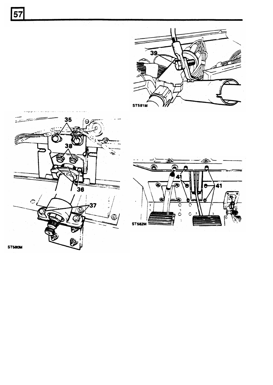
41.
Fit the pedal box and secure with the six
bolts. Fit the pedal assembly mill board trim
and secure with retaining strip, vent cover and
screws.
42.
Fit the master cylinder
to
the servo and
connect the servo vacuum hose.
43.
Connect the stop lamp switch leads.
Fitting steering column
34. Fit the main support bracket and padding to
the steering column and manoeuvre the
column into position in the vehicle.
35.
Loosely secure the main support bracket and
harness bracket to the bulkhead with
two
bolts.
36.
Loosely fit the clamp and rubber packing strip
to the column and retain with two bolts.
37. Loosely secure the lower end
of
the column to
the lower support bracket with two nuts and
bolts.
38. Loosely secure the clamp bracket to the main
support bracket with two bolts.
Fit steering column
lock switch
44. Place lock switch
in
position and rotate the
steering column inner shaft to line
up
the slot
with the switch plunger.
39. Working inside the vehicle cab, fit the tie-bar
to the column bracket and secure with the
single bolt.
40. Finally tighten the main support bracket bolts,
clamp bracket bolts, upper clamp bolts and
the lower support bracket nuts and bolts.
4
REISSUED: FEB 1993