Defender (1993+). Manual - part 69


  Index      Land Rover     Defender - service manual 1993 year


Search            


Content   ..  67  68  69  70   ..


Defender (1993+). Manual - part 69


FRONT 

AXLE AND 

FINAL DRIVE 

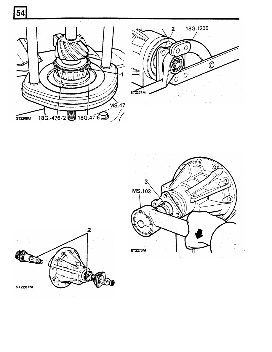
3.  Fit  a  suitable  socket  to  the  torque  pre-load 

meter  M.S.  103  or  a  suitable  alternative,  and 
check  the  pre-load  figure  by  turning  the 
pinion,  with  the  meter,  in  a  clockwise 
direction.  Continue to  tighten  the  nut  until  the 
gauge reads 2 to 4 Nm. 

4.  Note  that  i f  the  original,  bedded-in,  bearings 

are being refitted the pre-load figure should be 

1.2 to  1.7  Nm. 

The object  of the following instructions is 

to 

establish 

the  correct  height  of  the  pinion,  in  the  pinion 
housing, 

so  that  it 

will 

mesh correctly with the  crown 

wheel.  This  may  entail raising or  lowering the  pinion 
by adjusting the value of  the shims behind the pinion 
head  bearing  track.  In  order  to  achieve  this,  the 
pinion  bearings  must  be  temporarily  pre-loaded 

to 

the  same  figure  as  they  will  be when the  differential 
is finally assembled. 

2.  Insert  the  pinion  into  the  housing and 

fit 

the 

tail  bearing without any  pre-load shims.  Fit the 
spacer  and drive flange,  omit the oil seal,  and 
secure the assembly with  the washer  and nut. 
Restrain the flange with service 

tool 

18G 

1205 

or  the  reverse end 

of 

RO 

530105, 

and  slowly 

tighten  the  nut 

a  little  at  a  time  and  remove 

the flange restrainer. 

5.  Secure the pinion housing vertically in the vice 

so  that  the  pinion  is  uppermost.  It  will  be 
noted  that  in  addition  to  the  serial  number 
etched on  the pinion end face there may be a 
figure  with  a  minus  (-)  or  a  plus  (+)  sign 
before it.  This figure  indicates,  in thousandths 
of  an  inch,  whether  the  depth  of  the  pinion 
head,  (dimension A),  is under or oversize from 
the  designed  dimension.  A  pinion  without 
these  figures  must  be  set  in  the  pinion 

housing at the nominal  height dimension.  The 
nominal  height  dimension  is  represented  by 

the  pinion  height setting block  18G191-4.  The 
dimension 

I

S


taken from the pinion end face to 

the  lowest  point  i n   the  differential  carrier 

bearing saddle in the pinion housing. 

FRONT 

AXLE AND FINAL DRIVE 

7 .  

Ensure  that  the  pinion  head  is  clean  and 

smooth.  Transfer  the  gauge 

to 

the  pinion 

housing 

so  that  the  magnetic  base  sits 

centrally on the pinion end face and the stylus 
rests on the lowest  point 

in 

one 

of  the  carrier 

bearing  saddles. 

Make 

a  note 

of  the  dial 

gauge  reading 

from  the  zeroed  setting  and 

whether  the gauge needle moved up 

or  down. 

Now  move  the  dial gauge  across 

to 

the  other 

saddle  and  again  note  the  reading  from  the 
zeroed  setting.  Now  add  the  two  readings 
together  and  divide  by 

two 

to 

obtain  a  mean 

reading. 

6.  Remove  the  keep  disc  from  the  magnetic 

base  of  the  pinion  height  setting  dial  gauge 

18G  191  and  position  the  setting  block  18G 
191-4  and  gauge  on  a  surface  plate  as 

illustrated.  It  will  be  noted  that  the  setting 
block has three  setting  heights.  It is essential 

that  the  correct  setting  is  used  for  the 
differential  concerned.  Rest the  stylus  on  the 
setting  and  load  the  gauge  to  read 
approximately 0,40 mm and zero the gauge. 

8.  I f  the  dial  indicator  needle  did  not  reach  the 

zeroed  setting,  the  difference  between  this 

NOTE:  The  setting  block  dimensions  are  as 

setting  and  the  position  of  the  needle  is  the 

follows:  39,50  mm  Rationalised  axle  -  Latest 

thickness of  shims that must be removed 

from 

current  axle  metric  threaded  bearing 

cap  bolts. 

behind the  pinion head bearing track  to  lower 

38,10 

mm  Pre-Rationalised  axle  recognized  by 

the pinion to  the nominal dimension. 

the 

A/F 

threaded  bearing 

cap  bolts. 

30,93 

mm 

9.  I f  the  indicator  needle  moved  beyond  the 

Salisbury axle only. 

zeroed  setting,  the  difference  between  this 
setting  and  the  position  of  the  needle  is  the 
thickness  of  shims  that  must  be  added  to 
those behind the pinion  head  bearing track  to 

raise the pinion to the nominal dimension. 

FRONT AXLE 

AND 

FINAL 

DRIVE 

face  figure  of  + 3   the  dial  gauge  reading 

should  indicate  that  the  pinion  head  depth is 
indeed 0.003 in (0.0762 mm) oversize. 

Pinion bearing pre-load adjustment 

1. 

Position the  pinion  housing horizontally  in the 

vice.  From  the  pinion  housing  remove  the 
drive flange, spacer, tail bearing and  pinion. 

2.  Fit  a  new  shim  or  shims 

of 

the  same 

thickness  as  the  originals  to  the  pinion. 

If 

these are lost and the thickness is unknown 

fit 

shims 

to 

the value 

of  at  least 4,06  mm. 

3. 

Fit  the  pinion, 

with 

the  shims, 

to 

the  housing, 

then  the  tail  bearing  followed  by  the  spacer 

and  driving  flange.  Omit  the  oil  seal  at  this 
stage  and  secure  the  assembly  with  the 
washer and castellated nut. 

10. 

Before  actually  adjusting  the  shim  thickness, 

the  plus 

or  minus figure, 

if 

any,  on the  pinion 

face  must  be  taken  into  consideration  when 
calculating  the  final  thickness  of  shims  that 

must 

be removed or  added. 

4.  Tighten the  flange  nut 

to  the  specified  torque 

If the  pinion has  a  plus 

(+) 

figure  etched 

on 

whilst  holding the flange with  service 

tool 

18G 

the  pinion  face,  subtract  this  figure,  in 

1205,  as  before.  The  torque now  required  to 

thousandths  of  an  inch,  from  the  figure 

turn  the  pinion, 

if 

new  bearings  have  been 

obtained 

in instruction 

or 

9. 

If the pinion has 

fitted, should be between 

to 40  Nm once the 

a  minus 

(-) 

figure  on the  pinion face  add  this 

initial  inertia  has  been  overcome. 

If 

the 

to  that obtained 

in instructions 

or 

9. 

A  pinion 

original,  bedded-in,  bearings  have  been 

without  a  plus  or  minus  figure  must 

be 

refitted,  the  figure  should  be  between  1.2 

to 

adjusted 

to  the  nominal dimension and  shims 

1.7 

Nm. 

To  check  the  torque 

or  pre-load, use 

to 

the value indicated by the dial test indicator 

the Torque  meter 

M.S. 

103 

and  a socket  and 

in  instruction  - 

or 

9  should  be  added 

or 

turn the pinion whilst noting the meter reading. 

removed. 

If  necessary,  dismantle  the  pinion  assembly 

11. 

Remove  the  pinion  from  the  housing  and 

and  change  the  bearing  pre-load  shims 

in 

withdraw  the  pinion  head  bearing  track  as 

order 

to  achieve the  correct  torque  figure. As 

previously  described. 

Adjust 

the 

shim 

a  guide,  thicker  shims  will  reduce  the  torque 

thickness 

as 

required  by 

the 

above 

or  pre-load and thinner  shims will increase the 

calculations. Refit the  bearing track  and shims 

torque.  Reassemble  the  pinion  again  and 

and  ensure  that  once  again  the  track  is 

recheck the torque. 

pressed 

fully  home, 

12. 

Having  made  the  necessary  adjustments  the 

pinion height setting must be checked again to 

Having  established  the  correct  thickness  of 

ensure  that  the  calculations  and  adjustments 

shims  the  pinion  drive  flange 

must  be 

removed  to  fit  the  oil  seal.  Examine the  seal 

are  correct.  Refit  the  pinion 

to 

the  housing 

and  pre-load  the  bearings,  as  before, 

before  fitting 

to  ensure  that 

it 

is  clean  and 

repeating instructions 2  and 

above. Now  set 

undamaged,  since  even  a  small  scratch 

on 

up  the  dial  gauge  and  carry  out  the  pinion 

the  seal  lips could  impair  its ability 

to 

prevent 

height  check  again  exactly  as  described  in 

oil leaking. Also  check  that the garter  spring is 

instructions 

and 

7. 

If 

the  pinion  height 

properly located. Whilst  the distance piece can 

setting 

is 

correct,  the  mean  reading  obtained 

be  inserted after  the  seal  has  been fitted,  the 

will 

agree with  the figure etched on the pinion 

tail  bearing will  not  pass through the  seal, 

so 

Fitting pinion 

oil seal 

it  is  important  to  check  that  the  bearing  is  in 

FRONT AXLE AND FINAL DRIVE 

5. 

After  evenly  tightening  the  bearing  cap  bolts 
to 

the  correct  torque,  check  the  backlash 

again  to  ensure  that  it  has  not  altered  the 

setting.  Fit  the  locking  finger  and  secure  with 
the roll pin. 

6.  Locate  a  new  joint  washer  over  the  axle 

casing  studs,  liberally  lubricate  the  bearings 
and  gears and refit the differential assembly to 
the  axle. 

Fit 

and  tighten  the  retaining  nuts 

evenly 

to 

the correct torque. 

7.  Check  that  the  drain plug is  tight  and  remove 

the 

axle 

oil 

filler 

level 

plug. 

Inject 

approximately  1,70  litres  of  a  recommended 
axle 

oil 

until  it  begins 

to 

run 

from 

the  level 

hole.  Fit  and  tighten the  plug  and  wipe  away 
any  surplus oil. 


Content   ..  67  68  69  70   ..