Defender (1993+). Manual - part 68
FRONT
AXLE AND
FINAL
DRIVE
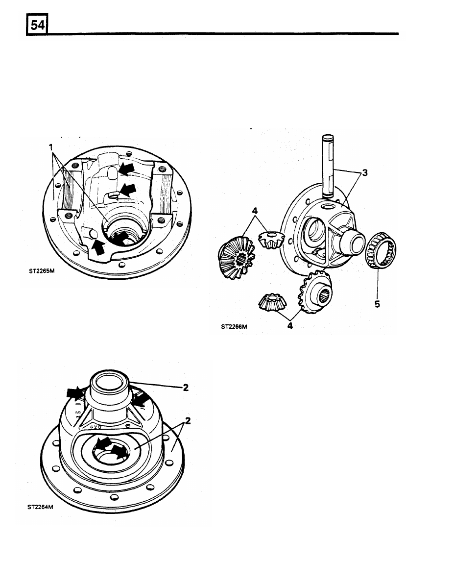
INSPECTION
4.
Carefully examine the sun and planet gears
for wear on the teeth and the running surfaces
1.
Examine the pinion housing for damage.
in contact with the carrier. Check also for
Check the machined surfaces and remove any
signs of over heating.
burrs. Check the carrier bearing nut threads in
5.
Inspect all the bearings for wear, pitting, flats
the housing and caps and adjusting nuts for
on the rollers and overheating.
If
the bearings
damage and repair as necessary. Make sure
are serviceable they can be refitted but
if
new
that the cast-in lubrication passages (arrowed)
ones are available they must be renewed
including the passage
to the
tail bearing, are
together with the tracks.
completely clear of any obstruction.
2. Examine the machined surfaces of the
differential carrier for damage, pitting, scores
and wear and in particular the surfaces on
which the sun and planet gears run. Also,
ensure that the four
lubrication holes
(arrowed) are clear. Any obstruction here
could cause future bearing failure.
6.
Examine the crown wheel and pinion for
excessive and abnormal wear and signs of
over-heating. Compare the
tooth
contact on
the crown wheel driving side with the
examples illustrated below. These examples,
however, are for the rear axle crown wheel
where the pinion
is
driven clockwise. Tooth
contact for the front axle crown wheel, where
the pinion is driven anticlockwise, is the same
but on the opposite side
of
the
tooth. The first
example
" A " shows the marks that should be
made by a correctly meshed crown wheel and
pinion.
The
remaining examples
show
incorrect tooth contact.
3.
Check the cross shaft
for
scores and pitting.
Insert the shaft in the carrier to check for
excessive wear.