Index Land Rover Defender - service manual 1993 year
Search
Content .. 70 71 72 73 ..
Defender (1993+). Manual - part 72
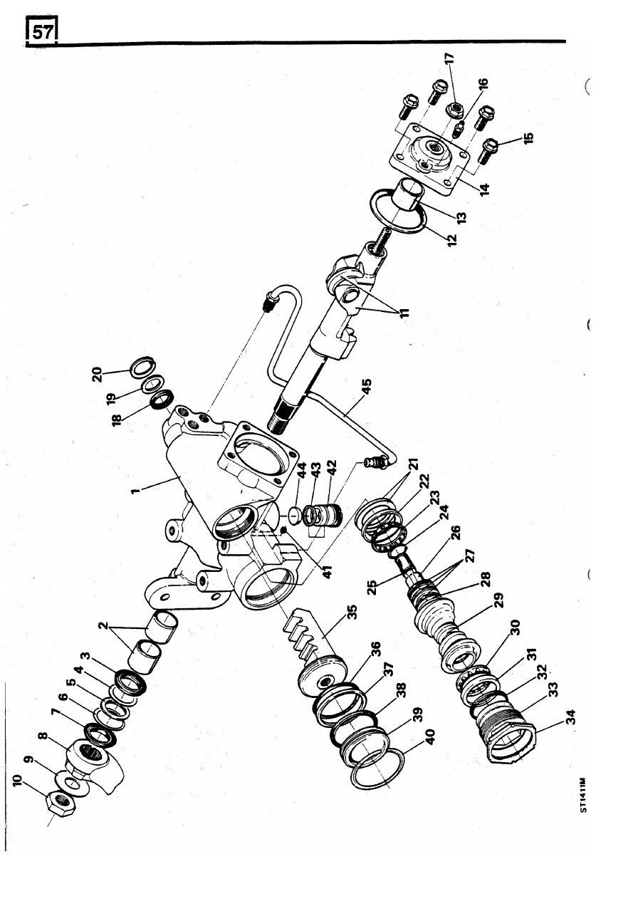
STEERING
8
REISSUED:
FEB
1993