Defender (1993+). Manual - part 59
LT230T
TRANSFER
GEARBOX
Differential lock switch adjustment
Transmission brake drum - re-assemble.
1.
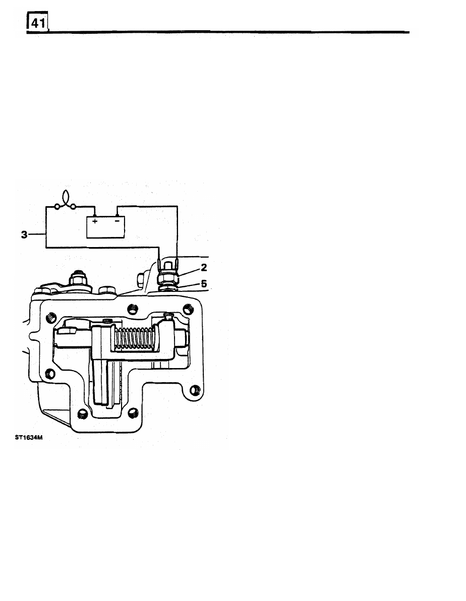
Select differential locked position by moving
1.
Clean brake backplate and oil catcher and
the lock taper towards the right side
of
the
apply sealant to the catcher joint face.
transfer box casing.
2.
Locate brake backplate on the rear output
2.
Apply sealant to the differential
lock
warning
housing with the brake operating lever on the
light switch and fit
to
the top of the front
right side
of
the transfer box casing.
output housing.
3.
Secure the backplate (including the oil
3.
Connect a test lamp circuit to the differential
catcher) with the four special bolts and tighten
lock
switch.
using a hexagonal socket to the specified
4.
Screw in the lock switch until the bulb is
torque.
illuminated.
4.
Clean and fit brake drum and secure with two
5.
Turn
in
the switch another half a turn and
tighten with the locknut against the housing.
6. Disconnect the battery and move
the
differential
lock
lever to the left to disengage
differential lock.
7.
Clean the front output housing side cover.
8.
Grease and fit side cover gasket.
9.
Apply Loctite 290 to bolt threads,
fit
side cover
and secure with seven bolts and washers.
countersunk screws.