Defender. Manual - part 267


  Index      Land Rover     Land Rover Defender - service manual 2007 year


Search            


Content   ..  265  266  267  268   ..


Defender. Manual - part 267


Handles, Locks, Latches and Entry Systems - Front Door Latch

Removal and Installation

Removal

1. Remove door reinforcing panel and support glass with

timber. 

For additional information, refer to: 

Front Door Reinforcement

Panel

 (501-03 Body Closures, Removal and Installation).

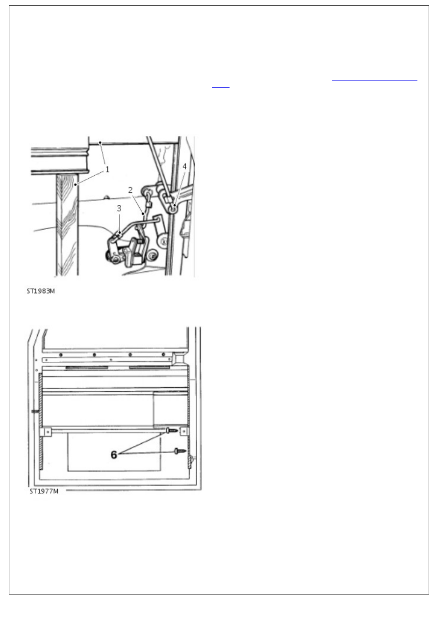
2. Disconnect control rod from handle operating lever.
3. Disconnect control rod from locking lever on handle.

4. Disconnect push button control rod and linkage from latch

mechanism.

5. Remove 2 screws and remove handle assembly from door.

6. Remove 2 self-tapping screws retaining lower end of

window glass runner.

7. Remove 3 screws securing latch assembly to door.

7. Remove 3 screws securing latch assembly to door.

8. Whilst taking care not to damage runner, ease runner away

from latch and manoeuvre latch assembly from door.

Installation

1. Carefully ease window runner away, sufficiently to enable

latch to be located into position.

2. Secure latch to door with 3 screws.
3. Secure window runner with 2 screws ensuring that packing

strip is in position and that screw heads are below bottom of

runner to prevent damage to glass.

4. Install handle with 2 screws, ensuring that bezels are in

position.

5. Connect control rod to handle operating lever and secure

with spring clip.

6. Connect control rod to locking lever and retain with spring

clip.

7. Connect push button control rod and linkage to latch lever

and secure with spring clip.

8. Install mounting panel. 

For additional information, refer to: 

Front Door Reinforcement

Panel

 (501-03 Body Closures, Removal and Installation).

Handles, Locks, Latches and Entry Systems - Rear Door Latch

Removal and Installation

Removal

1. Remove door trim panel. 

For additional information, refer to: 

Rear Door Trim Panel

(501-05 Interior Trim and Ornamentation, Removal and

Installation).

2. Peel-back sufficient of plastic sheet to reveal latch.
3. Release remote control lever rod from latch assembly.
4. Disconnect door outer handle control rod from latch

assembly.

5. Disconnect door locking button remote control rod from latch

mechanism.

6. Remove 3 retaining screws and withdraw latch assembly

from door.

Installation

1. Install latch assembly to door and secure with 3 screws,

noting that uppermost screw is longer.

2. Connect remote control levers to latch mechanism reversing

instructions 3, 4 and 5.

3. Re-seal plastic sheet and install door trim panel. 

For additional information, refer to: 

Rear Door Trim Panel

(501-05 Interior Trim and Ornamentation, Removal and

Installation).

Handles, Locks, Latches and Entry Systems - Door Lock Cylinder

Removal and Installation

Removal

1. Remove door trim panel and plastic sheet. 

For additional information, refer to: 

Front Door Trim Panel

(501-05 Interior Trim and Ornamentation, Removal and

Installation).

2. Remove reinforcement panel. 

For additional information, refer to: 

Front Door Reinforcement

Panel

 (501-03 Body Closures, Removal and Installation).

3. Raise and support glass to gain access to latch mechanism.
4. Release spring clip and disconnect rod from lock operating

lever.

5. Remove single screw and withdraw lock lever assembly.

6. Withdraw lock barrel from exterior door handle complete

with locking sleeve.

7. To remove barrel from plastic retaining sleeve, depress


Content   ..  265  266  267  268   ..