Defender. Manual - part 144
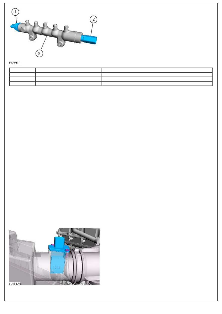
Item
Part Number
Description
1
-
Fuel pressure sensor
2
-
Pressure limiting valve
3
-
Fuel rail
The fuel rail pressure sensor is located forward end of the fuel rail. The fuel rail pressure sensor measures the pressure
of the fuel in the fuel rail. This input is then used by the ECM to control the amount of fuel delivered to the fuel rail.
FUEL RAIL PRESSURE RELIEF VALVE
The fuel rail pressure relief valve is located at the rear end of the fuel rail. To prevent damage to the high pressure fuel
system, the valve opens when the fuel pressure in the rail reaches approximately 2000 bar. The ECM detects the valve
opening and sends a malfunction indicator lamp (MIL) request to the instrument cluster.
Once the valve has been opened it needs to be replaced.
FUEL TEMPERATURE SENSOR
The fuel temperature sensor is located in the high pressure fuel pump.
The sensor is an NTC sensor which is connected to the ECM by two wires. The ECM fuel temperature sensor circuit
consists of an internal voltage divider circuit which incorporates an NTC thermistor. As the fuel temperature rises the
resistance through the sensor decreases. The output from the sensor is the change in voltage as the thermistor allows
more current to pass to earth relative to the temperature of the fuel.
The ECM monitors the fuel temperature constantly. If the fuel temperature exceeds 85°Celsius (185°F), the ECM invokes
an engine 'derate' strategy. This reduces the amount of fuel delivered to the injectors in order to allow the fuel to cool.
When this occurs, the driver may notice a loss of performance.
Further fuel cooling is available by a bi-metallic valve diverting fuel through the fuel cooler when the fuel reaches a
predetermined temperature. In hot climate markets, an electrically operated cooling fan is positioned in the air intake
ducting to the fuel cooler. This is controlled by a thermostatic switch, which switches the fan on and off when the fuel
reaches a predetermined temperature.
The wires to the fuel sensor are monitored by the ECM for short and open circuit. The ECM also monitors the 5V supply.
If a failure occurs a fault is recorded in the ECM memory and the ECM uses a default fuel pressure value.
If the ECM registers an 'out of range' deviation between the pressure signal from the sensor and the pre-programmed
'set point' a fault is stored in the ECM memory. Depending on the extent of the deviation, the ECM will reduce the
injection quantity, stop the engine immediately or prevent further engine starting.
MAF SENSOR
Two MAF sensor is located on the intake air duct directly after the air filter box. The sensor is housed in a plastic
molding which is connected between the intake manifold and the air intake pipe.