Jeep Wagoneer (2024 year). Manual in english - page 9
 

  Index      Manuals     Jeep Wagoneer (2024 year). Manual in english


Search            copyright infringement  


Content      ..     7      8      9      10     ..


Jeep Wagoneer (2024 year). Manual in english - page 9


IN CASE OF EMERGENCY

HAZARD WARNING FLASHERS

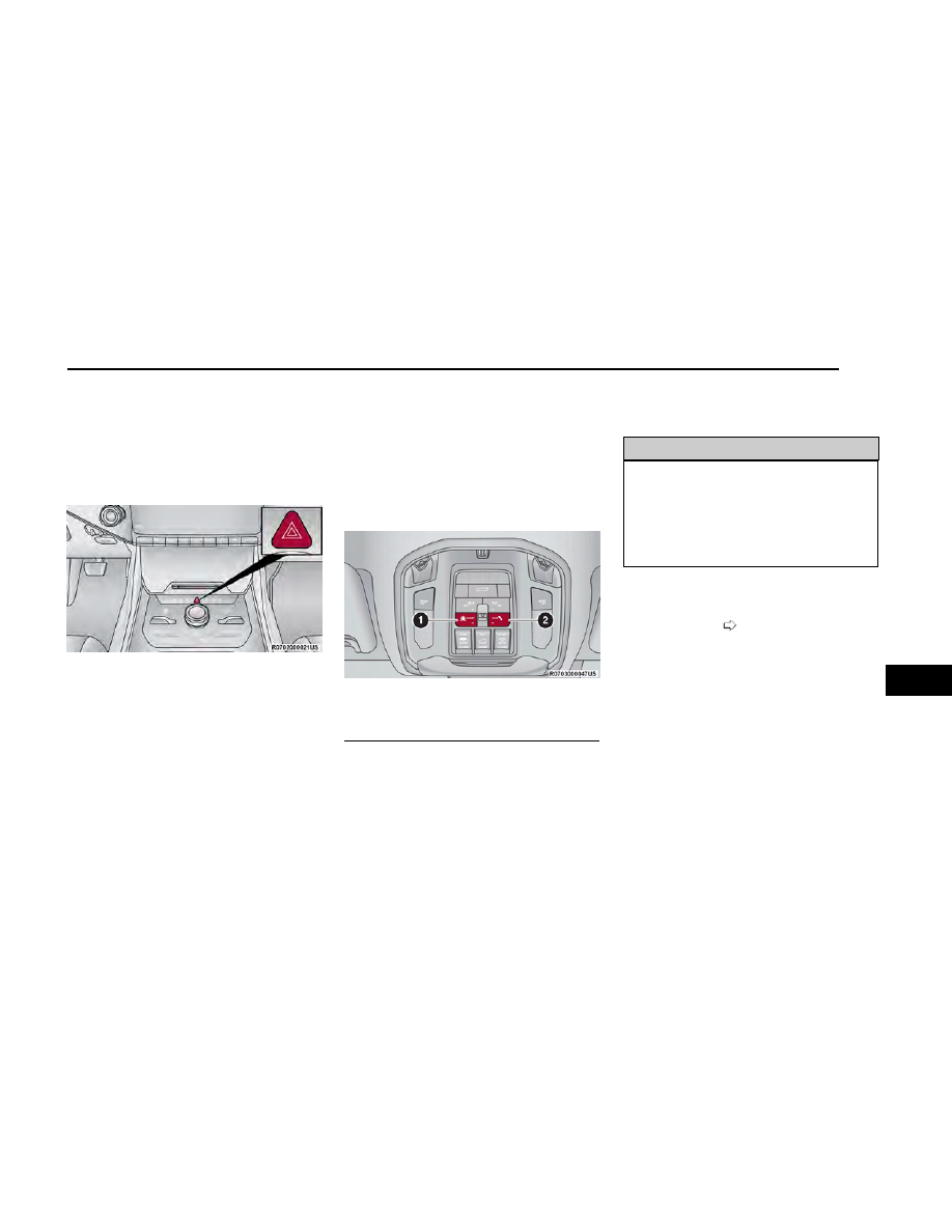
The Hazard Warning Flashers button is located in the
center console just below the climate control screen.

Push the button to turn on the Hazard Warning Flash-
ers. When the button is activated, all directional turn
signals will flash on and off to warn oncoming traffic of
an emergency. Push the button a second time to turn
off the Hazard Warning Flashers.

This is an emergency warning system and it should not
be used when the vehicle is in motion. Use it only when
your vehicle is disabled or signaling a safety hazard
warning for other motorists.

When you must leave the vehicle to seek assistance,
the Hazard Warning Flashers will continue to operate
even though the ignition is placed in the OFF position.

NOTE:

With extended use, the Hazard Warning Flashers may
discharge the battery.

ASSIST AND SOS SYSTEM— IF EQUIPPED

If equipped, the overhead console contains an ASSIST
and SOS button.

WARNING!

ALWAYS obey traffic laws and pay attention to the
road. ALWAYS drive safely with your hands on the
steering wheel. You have full responsibility and
assume all risks related to the use of the features
and applications in this vehicle. Only use the features
and applications when it is safe to do so. Failure to do
so may result in an accident involving serious injury
or death.

NOTE:

Your vehicle may be transmitting data as authorized
by the subscriber

page 351.

The ASSIST and SOS buttons will only function if you
are connected to an operable LTE (voice/data) or 4G
(data) network, which comes as a built-in function.
Other Uconnect services will only be operable if your
Wagoneer Connect service is active and you are
connected to an operable LTE (voice/data) or 4G
(data) network.

ASSIST Call

The ASSIST button is used to automatically connect you
to any one of the following support centers:

Roadside Assistance – If you get a flat tire, or need
a tow, just push the ASSIST button and you will be
connected to a representative for assistance. Road-
side Assistance will know what vehicle you’re driving
and its location. Additional fees may apply for road-
side assistance.

Hazard Warning Flashers Button

Assist And SOS Buttons

1 — ASSIST Button
2 — SOS Button

273

7

Vehicle Customer Care -Total support for all other
vehicle issues.

Uconnect Customer Care - Total support for Radio,
Connected Services, Phone and NAV issues.

SOS Call

1. Push the SOS Call button on the overhead console.

NOTE:

In case the SOS Call button is pushed in error, there
will be a 10 second delay before the SOS Call sys-
tem initiates a call to an SOS operator, during which
the LED will blink green. To cancel the SOS Call con-
nection, push the SOS call button on the overhead
console or press the cancellation button on the
Device Screen. Termination of the SOS Call will turn
off the green LED light on the overhead console.

2. The LED light located within the ASSIST and SOS

buttons on the overhead console will turn green
once a connection to an SOS operator has been
made.

3. Once a connection between the vehicle and an SOS

operator is made, the SOS Call system may transmit
the following important vehicle information to an
SOS operator:

Indication that the occupant placed an SOS Call

The vehicle brand

The last known GPS coordinates of the vehicle

4. You should be able to speak with the SOS operator

through the vehicle audio system to determine if
additional assistance is needed.

WARNING!

ALWAYS obey traffic laws and pay attention to the
road. ALWAYS drive safely with your hands on the
steering wheel. You have full responsibility and
assume all risks related to the use of the features
and applications in this vehicle. Only use the features
and applications when it is safe to do so. Failure to do
so may result in an accident involving serious injury
or death.

NOTE:

Your vehicle may be transmitting data as autho-
rized by the subscriber.

Once a connection is made between the vehi-
cle’s SOS Call system and the SOS operator, the
SOS operator may be able to open a voice con-
nection with the vehicle to determine if addi-
tional assistance is needed. Once the SOS opera-
tor opens a voice connection with the vehicle’s
SOS Call system, the operator should be able to
speak with you or other vehicle occupants and
hear sounds occurring in the vehicle. The vehi-
cle’s SOS Call system will attempt to remain con-
nected with the SOS operator until the SOS
operator terminates the connection.

5. The SOS operator may attempt to contact appropri-

ate emergency responders and provide them with
important vehicle information and GPS coordinates.

WARNING!

If anyone in the vehicle could be in danger (e.g.,
fire or smoke is visible, dangerous road conditions
or location), do not wait for voice contact from an
Emergency Services Agent. All occupants should
exit the vehicle immediately and move to a safe
location.

Never place anything on or near the vehicle’s oper-
able network and GPS antennas. You could pre-
vent operable network and GPS signal reception,
which can prevent your vehicle from placing an
emergency call. An operable network and GPS sig-
nal reception is required for the SOS Call system to
function properly.

The SOS Call system is embedded into the vehi-
cle’s electrical system. Do not add aftermarket
electrical equipment to the vehicle’s electrical sys-
tem. This may prevent your vehicle from sending a
signal to initiate an emergency call. To avoid inter-
ference that can cause the SOS Call system to fail,
never add aftermarket equipment (e.g., two-way
mobile radio, CB radio, data recorder, etc.) to your
vehicle’s electrical system or modify the antennas
on your vehicle. IF YOUR VEHICLE LOSES BATTERY
POWER FOR ANY REASON (INCLUDING DURING OR
AFTER AN ACCIDENT), THE UCONNECT FEATURES,
APPS AND SERVICES, AMONG OTHERS, WILL NOT
OPERATE.

Modifications to any part of the SOS Call system
could cause the air bag system to fail when you
need it. You could be injured if the air bag system
is not there to help protect you.

274

IN CASE OF EMERGENCY

SOS Call System Limitations

Vehicles sold in Mexico

DO NOT

have SOS Call system

capabilities.

SOS or other emergency line operators in Mexico may
not answer or respond to SOS system calls.

If the SOS Call system detects a malfunction, any of the
following may occur at the time the malfunction is
detected, and at the beginning of each ignition cycle:

The overhead console lights located within the
ASSIST and SOS buttons will continuously illuminate
red.

The Device Screen will display the following mes-
sage “Vehicle Device Requires Service. Please Con-
tact An Authorized Dealer.”

An in-vehicle audio message will state “Vehicle
device requires service. Please contact an autho-
rized dealer.”

WARNING!

Ignoring the overhead console light could mean
you will not have SOS Call services. If the overhead
console light is illuminated, have an authorized
dealer service the SOS Call system immediately.

The Occupant Restraint Control module turns on
the Air Bag Warning Light on the instrument panel
if a malfunction in any part of the system is
detected. If the Air Bag Warning Light is illumi-
nated, have an authorized dealer service the Occu-
pant Restraint Control system immediately.

Even if the SOS Call system is fully functional, factors
beyond FCA US LLC’s control may prevent or stop the
SOS Call system operation.

These include, but are not limited to, the following fac-
tors:

The ignition is in the OFF position

The vehicle’s electrical systems are not intact

The SOS Call system software and/or hardware are
damaged during a crash

The vehicle battery loses power or becomes discon-
nected during a vehicle crash

LTE (voice/data) or 4G (data) network and/or Global
Positioning Satellite signals are unavailable or
obstructed

Equipment malfunction at the SOS operator facility

Operator error by the SOS operator

LTE (voice/data) or 4G (data) network congestion

Weather

Buildings, structures, geographic terrain, or tunnels

WARNING!

ALWAYS obey traffic laws and pay attention to the
road. ALWAYS drive safely with your hands on the
steering wheel. You have full responsibility and
assume all risks related to the use of the features
and applications in this vehicle. Only use the features
and applications when it is safe to do so. Failure to do
so may result in an accident involving serious injury
or death.

NOTE:

Your vehicle may be transmitting data as authorized
by the subscriber.

Never place anything on or near the vehicle’s LTE
(voice/data) or 4G (data) and GPS antennas. You
could prevent LTE (voice/data) or 4G (data) and GPS
signal reception, which can prevent your vehicle
from placing an emergency call. An operable LTE
(voice/data) or 4G (data) network connection and a
GPS signal is required for the SOS Call system to
function properly.

NOTE:

Changes or modifications not expressly approved by the
party responsible for compliance could void the user's
authority to operate the equipment.

CAUTION!

To avoid damage to the mirror during cleaning, never
spray any cleaning solution directly onto the mirror.
Apply the solution onto a clean cloth and wipe the
mirror clean.

Automatic SOS — If Equipped

Automatic SOS is a hands-free safety service that can
immediately connect you with help in the event that
your vehicle’s air bags deploy. Please refer to your pro-
vided radio supplement for complete information.

JACKING AND TIRE CHANGING

Use this QR code to access your digital
experience.

Scan me

IN CASE OF EMERGENCY

275

7

WARNING!

Do not attempt to change a tire on the side of the
vehicle close to moving traffic. Pull far enough off
the road to avoid the danger of being hit when
operating the jack or changing the wheel.

Being under a jacked-up vehicle is dangerous. The
vehicle could slip off the jack and fall on you. You
could be crushed. Never put any part of your body
under a vehicle that is on a jack. If you need to get
under a raised vehicle, take it to a service center
where it can be raised on a lift.

Never start or run the engine while the vehicle is
on a jack.

The jack is designed to be used as a tool for
changing tires only. The jack should not be used to
lift the vehicle for service purposes. The vehicle
should be jacked on a firm level surface only. Avoid
ice or slippery areas.

NOTE:

If your vehicle is equipped with an air suspension sys-
tem, there is a feature which allows the automatic level-
ing to be disabled before changing a tire. This feature
can be activated through the Uconnect system

page 200.

PREPARATIONS FOR JACKING

Before changing a tire or using the jack please disable
the hands free lift gate, This feature can be disabled
through the Uconnect system

page 182.

1. Park the vehicle on a firm, level surface as far from

the edge of the roadway as possible. Avoid icy or
slippery areas.

WARNING!

Do not attempt to change a tire on the side of the
vehicle close to moving traffic. Pull far enough off the
road to avoid being hit when operating the jack or
changing the wheel.

2. Turn on the Hazard Warning Flashers.

3. Apply the parking brake.

4. Place the gear selector into PARK (P).

5. Turn OFF the ignition.

6. Block both front and rear of the wheel diagonally

opposite of the jacking position. For example, if
changing the driver’s front tire, block the passen-
ger’s rear wheel.

NOTE:

Passengers should not remain in the vehicle when the
vehicle is being raised or lifted.

JACK AND TOOLS LOCATION

The scissor-type jack and tire changing tools are
located in the rear cargo area, under the load floor.

1. Lift up on the load floor handle to access the jack

and tool storage.

2. Remove the jack storage cover to access the jack

and tools.

Wheel Blocked Example

Load Floor Handle

Jack And Tools Access Cover

276

IN CASE OF EMERGENCY

3. Pull up to remove jack and tools from storage.

NOTE:

Depending on vehicle trim level, tools shown may vary.

SPARE TIRE STOWAGE

The spare tire is stowed under the rear of the vehicle by
means of a cable winch mechanism. To remove or stow
the spare, use the jack handle/lug wrench connected
to the square socket extension to rotate the “spare tire
drive” nut. The nut is located under a rubber plug at the
center-rear of the cargo floor area, just inside the lift-
gate opening.

CAUTION!

The winch mechanism is designed for use with the
jack wrench extension tool only. Use of air wrench or
power tool may damage the winch.

SPARE TIRE REMOVAL

Remove the spare tire before attempting to jack up the
vehicle. The spare tire is stowed underneath the rear
cargo area on the outside of the vehicle.

1. Assemble the jacking tools.

Removing Jack And Tools

Jack And Tools Storage

Jacking Tools Description

1 — Tow Hook (If Equipped)
2 — Wheel Lug Wrench
3 — Jack Handle Extension
4 — Fuel Funnel
5 — Jack Handle
6 — Scissor Jack

Spare Tire Location

IN CASE OF EMERGENCY

277

7

2. Locate and remove plug from the storage compart-

ment floor to expose the winch access hole.

3. Fit the jack handle extension over the drive nut. Use

the wheel lug wrench and extension to completely
lower the spare tire. Keep turning the handle coun-
terclockwise until the winch stops.

4. Slide the tire out from under the vehicle and rotate it

vertically behind the rear fascia/bumper.

5. Pull the metal retainer toward you to release it.

6. Slide the retainer up the steel extension tube and

winch cable. Rotate the retainer and push it through
the hole in the wheel.

JACKING INSTRUCTIONS

WARNING!

Carefully follow these tire changing warnings to help
prevent personal injury or damage to your vehicle:

Always park on a firm, level surface as far from the
edge of the roadway as possible before raising the
vehicle.

Turn on the Hazard Warning Flashers.

Apply the parking brake firmly and set the trans-
mission in PARK.

Block the wheel diagonally opposite the wheel to
be raised.

Never start or run the engine with the vehicle on a
jack.

(Continued)

Jacking Tool Assembly

1 — Wheel Lug Wrench
2 — Jack Handle Extension
3 — Jack Handle

Winch Nut Plug

Winch Drive Nut Location

Wrench Rotation

Releasing Winch Retainer

278

IN CASE OF EMERGENCY

WARNING!

Do not let anyone sit in the vehicle when it is on a
jack.

Do not get under the vehicle when it is on a jack. If
you need to get under a raised vehicle, take it to a
service center where it can be raised on a lift.

Only use the jack in the positions indicated and for
lifting this vehicle during a tire change.

If working on or near a roadway, be extremely care-
ful of motor traffic.

To assure that spare tires, flat or inflated, are
securely stowed, spares must be stowed with the
back of the wheel facing the ground.

The jack should be used on level firm ground wher-
ever possible.

It is recommended that the wheels of the vehicle
be chocked, and that no person should be remain
in a vehicle that is being jacked.

No person should place any portion of their body
under a vehicle that is supported by a jack.

1. Loosen (but do not remove) the wheel lug nuts,

using the lug wrench by turning them counterclock-
wise, one turn, while the wheel is still on the ground.

2. Assemble the jack and tools

page 277.

NOTE:

Placement for the front and rear jacking locations
are critical. Keep the jack and tools aligned while
raising the vehicle to prevent tool damage. See the
following images for proper jacking locations.

CAUTION!

Do not attempt to raise the vehicle by jacking on loca-
tions other than those indicated in the Jacking
Instructions for this vehicle.

3. When changing a front tire, place the scissor jack

under the front chassis lifting point, as indicated by
the triangular lift point symbol shown in the follow-
ing image.

Do not raise the vehicle until you are

sure the jack is fully engaged.

Jack Warning Label

Loosen Lug Nuts

Jack And Tool Assembled

Jacking Locations

IN CASE OF EMERGENCY

279

7

4. When changing a rear tire, place the scissor jack

under the rear chassis lifting point, as indicated by
the triangular lift point symbol shown in the follow-
ing image.

Do not raise the vehicle until you are

sure the jack is fully engaged.

5. Raise the vehicle by using the wheel lug wrench and

jack handle to turn the jack screw clockwise. Raise
the vehicle only until the tire just clears the surface
and enough clearance is obtained to install the
spare tire. Minimum tire lift provides maximum
stability.

WARNING!

Raising the vehicle higher than necessary can make
the vehicle less stable. It could slip off the jack and
hurt someone near it. Raise the vehicle only enough
to remove the tire.

6. Remove the lug nuts and wheel.

7. Position the spare wheel/tire on the vehicle and

install the lug nuts with the cone-shaped end toward
the wheel. Lightly tighten the nuts.

CAUTION!

Be sure to mount the spare tire with the valve stem
facing outward. The vehicle could be damaged if the
inflatable spare tire is mounted incorrectly.

Front Lifting Point

Front Jacking Location

Rear Lifting Point

Rear Jacking Location

Mounting Spare Tire

280

IN CASE OF EMERGENCY

WARNING!

To avoid the risk of forcing the vehicle off the jack, do
not tighten the wheel nuts fully until the vehicle has
been lowered. Failure to follow this warning may
result in serious injury.

8. Lower the vehicle by turning the jack screw counter-

clockwise, and remove the jack and wheel blocks.

9. Finish tightening the lug nuts. Push down on the

wrench at the end of the handle for increased lever-
age. Tighten the lug nuts in a star pattern until each
nut has been tightened twice. For correct lug nut
torque

page 342. If in doubt about the correct

tightness, have them checked with a torque wrench
by an authorized dealer or at a service station.

10. Position the wheel behind the rear fascia/bumper

with the valve stem facing inward. Push the end of
the winch’s cable, spring and steel sleeve through
the front side of the road wheel. Making sure the
back of the wheel is facing the ground when the
wheel is stowed.

11. Slide the road wheel on the ground until it is

directly under the winch and between the rear
fascia/bumper and exhaust system heat shields.
Raise the tire by turning the lug wrench on the
winch extension clockwise until it clicks/ratchets
three times to make sure the cable is tight.

NOTE:

Double check to ensure the tire is snug against the
underbody of the vehicle. Damage to the winch
cable may result if the vehicle is driven with the tire
loose.

WARNING!

A loose tire or jack thrown forward in a collision or
hard stop could endanger the occupants of the
vehicle. Always stow the jack parts and the spare tire
in the places provided. Have the deflated (flat) tire
repaired or replaced immediately.

12. Lower the jack to the fully closed position.

13. Return the Jack and tools back into the jack stor-

age bin. Reinstall the jack storage cover by firmly
pushing down until the clips lock into position.

14. After 25 miles (40 km), check the lug nut torque

with a torque wrench to ensure that all lug nuts are
properly seated against the wheel.

Tighten Lug Nuts

Reinstalling Winch Retainer

Storing Of Road Wheel

Road Wheel Stowage

IN CASE OF EMERGENCY

281

7

15. Have the road wheel and tire repaired as soon as

possible and properly secure the spare tire, jack
and tool kit.

NOTE:

Do not drive with the spare tire installed for more than
50 miles (80 km) at a max speed of 50 mph (80 km/h).

JUMP STARTING

If your vehicle has a discharged battery, it can be jump
started using a set of jumper cables and a battery in
another vehicle, or by using a portable battery booster
pack. Jump starting can be dangerous if done improp-
erly, so please follow the procedures in this section
carefully.

WARNING!

Do not attempt jump starting if the battery is frozen. It
could rupture or explode and cause personal injury.

CAUTION!

Do not use a portable battery booster pack or any
other booster source with a system voltage greater
than 12 Volts or damage to the battery, starter motor,
alternator or electrical system may occur.

NOTE:

When using a portable battery booster pack, follow the
manufacturer's operating instructions and precautions.

PREPARATIONS FOR JUMP START

The battery in your vehicle is located in the front of the
engine compartment, behind the left headlight
assembly.

NOTE:

The positive

(+)

battery post may be covered with a pro-

tective cap. Lift up on the cap to gain access to the
positive battery post. Do not jump off fuses. Only jump
directly off positive post which has a positive

(+)

symbol

on or around the post.

See the following steps to prepare for jump starting:

1. Apply the parking brake, shift the automatic trans-

mission into PARK (P) and turn the ignition OFF.

2. Turn off the heater, radio, and all electrical

accessories.

3. If using another vehicle to jump start the battery,

park the vehicle within the jumper cables’ reach,
apply the parking brake and make sure the ignition
is OFF.

WARNING!

Do not allow vehicles to touch each other as this
could establish a ground connection and personal
injury could result.

NOTE:

Be sure that the disconnected cable ends do not touch
each other, or either vehicle, until properly connected
for jump starting.

WARNING!

Take care to avoid the radiator cooling fan when-
ever the hood is raised. It can start anytime the
ignition switch is ON. You can be injured by moving
fan blades.

Remove any metal jewelry such as rings, watch
bands and bracelets that could make an inadver-
tent electrical contact. You could be seriously
injured.

Batteries contain sulfuric acid that can burn your
skin or eyes and generate hydrogen gas which is
flammable and explosive. Keep open flames or
sparks away from the battery.

Positive (+) Jump Starting Post

282

IN CASE OF EMERGENCY

JUMP STARTING PROCEDURE

WARNING!

Failure to follow this jump starting procedure could
result in personal injury or property damage due to
battery explosion.

CAUTION!

Failure to follow these procedures could result in
damage to the charging system of the booster vehicle
or the discharged vehicle.

NOTE:

Make sure at all times that unused ends of jumper
cables are not contacting each other or either vehicle
while making connections.

Connecting The Jumper Cables

1. Connect the positive

(+)

end of the jumper cable to

the positive

(+)

post of the discharged vehicle.

2. Connect the opposite end of the positive

(+)

jumper

cable to the positive

(+)

post of the booster battery.

3. Connect the negative

(-)

end of the jumper cable to

the negative

(-)

post of the booster battery.

4. Connect the opposite end of the negative

(-)

jumper

cable to a good engine ground. A “ground” is an
exposed metallic/unpainted part of the engine,
frame or chassis, such as an accessory bracket or
large bolt. The ground must be away from the bat-
tery and the fuel injection system.

WARNING!

Do not connect the jumper cable to the negative

(-)

post of the discharged battery. The resulting electrical
spark could cause the battery to explode and could
result in personal injury.

5. Start the engine in the vehicle that has the booster

battery, let the engine idle a few minutes, and then
start the engine in the vehicle with the discharged
battery.

CAUTION!

Do not run the booster vehicle engine above
2,000 RPM since it provides no charging benefit,
wastes fuel, and can damage booster vehicle engine.

6. Once the engine is started, see the following discon-

necting procedure.

Disconnecting The Jumper Cables

1. Disconnect the negative

(-)

end of the jumper cable

from the engine ground of the vehicle with the dis-
charged battery.

2. Disconnect the opposite end of the negative

(-)

jumper cable from the negative

(-)

post of the

booster battery.

3. Disconnect the positive

(+)

end of the jumper cable

from the positive

(+)

post of the booster battery.

4. Disconnect the opposite end of the positive

(+)

jumper cable from the positive

(+)

post of the dis-

charged vehicle.

5. Reinstall the protective cover over the positive

(+)

post of the discharged vehicle.

If frequent jump starting is required to start your vehicle
have the battery and charging system tested at an
authorized dealer.

CAUTION!

Accessories plugged into the vehicle power outlets
draw power from the vehicle’s battery, even when not
in use (i.e., cellular devices, etc.). Eventually, if
plugged in long enough without engine operation, the
vehicle’s battery will discharge sufficiently to degrade
battery life and/or prevent the engine from starting.

Jump Starting Label

IN CASE OF EMERGENCY

283

7

REFUELING IN EMERGENCY

The vehicle is equipped with a refueling funnel for a
capless fuel system, which is located with the jack and
tools

page 276. If emergency refueling is neces-

sary, use an approved gas can and insert the refueling
funnel into the filler neck opening.

NOTE:

In certain cold conditions, ice may prevent the fuel door
from opening. If this occurs, lightly push around the
perimeter of the fuel door to break the ice buildup and
re-release the fuel door by pushing on the rear outer
edge near the center to unlatch. Do not pry on the door.

CAUTION!

To avoid fuel spillage and overfilling, do not “top off”
the fuel tank after filling.

Emergency Gas Can Refueling

Most gas cans will not open the flapper doors. A funnel
is provided to allow emergency refueling with a gas can.

See the following steps for refueling:

1. Retrieve funnel from the rear cargo storage area.

2. Insert funnel into the fuel filler pipe opening.

3. Ensure funnel is inserted fully to hold flapper doors

open.

4. Pour fuel into funnel opening.

5. Remove funnel from filler pipe, clean off prior to

putting back in the spare tire storage area.

WARNING!

Never have any smoking materials lit in or near the
vehicle when the fuel door is open or the tank is
being filled.

(Continued)

WARNING!

Never add fuel when the engine is running. This is
in violation of most state and federal fire regula-
tions and may cause the Malfunction Indicator
Light to turn on.

A fire may result if fuel is pumped into a portable
container that is inside of a vehicle. You could be
burned. Always place fuel containers on the
ground while filling.

IF YOUR ENGINE OVERHEATS

If the vehicle is overheating, it will need to be serviced
by an authorized dealer.

Potential signs of vehicle overheating can be:

Temperature gauge is at HOT (H)

Strong smell of coolant

White smoke coming from engine or exhaust

Coolant bottle coolant has bubbles present

WARNING!

You or others can be badly burned by hot engine cool-
ant (antifreeze) or steam from your radiator. If you
see or hear steam coming from under the hood, do
not open the hood until the radiator has had time to
cool. Never try to open a cooling system pressure cap
when the radiator or coolant bottle is hot.

If the temperature gauge is moving towards or close to
the HOT (H) position, the following actions will reduce
the potential for overheating.

On highways — slow down.

Refueling Funnel Location

Inserting Funnel

284

IN CASE OF EMERGENCY

In city traffic — while stopped, place the transmis-
sion in NEUTRAL (N), but do not increase the engine
idle speed while preventing vehicle motion with the
brakes.

Turn off the A/C. The A/C system adds heat to the
engine cooling system and turning the A/C off can
help remove this heat.

Turn the temperature control to maximum heat, the
mode control to floor and the blower control to high.
This allows the heater core to act as a supplement
to the radiator and aids in removing heat from the
engine cooling system.

CAUTION!

Driving with a hot cooling system could damage your
vehicle. If the temperature gauge reads HOT (H), as
soon as it’s safe, pull over and stop the vehicle. Idle
the vehicle with the air conditioner turned off until the
pointer drops back into the normal range. If the
pointer remains on HOT (H), and you hear continuous
chimes, turn the engine off immediately and call for
service.

MANUAL PARK RELEASE

WARNING!

You should be seated in the driver’s seat with your
foot firmly placed on the brake pedal to maintain con-
trol of the vehicle before activating the Manual Park
Release. If possible, you should apply the parking
brake. Activating the Manual Park Release will allow
your vehicle to roll away if it is not secured or properly
connected to a tow vehicle. Activating the Manual

(Continued)

WARNING!

Park Release on an unsecured vehicle could lead to
serious injury or death for those in or around the
vehicle.

To move the vehicle in cases where the transmission
will not shift out of PARK (P) (such as a depleted bat-
tery), a Manual Park Release is available.

Follow These Steps To Activate The Manual Park
Release:

1. Apply firm pressure to the brake pedal while seated

in the driver’s seat.

2. Apply the Electric Park Brake (EPB), if possible.

3. Using a flathead screwdriver or similar tool, remove

the Manual Park Release access cover, which is to
the lower left of the steering column, below the EPB
switch.

4. To unlock handle, insert a flathead screwdriver or

similar tool into the lock release, rotate a quarter
turn counterclockwise and hold simultaneously pull-
ing on the tether strap.

5. Pull the tether strap out as far as it will go, then

release it. The transmission should now be in NEU-
TRAL (N), allowing the vehicle to be moved.

Manual Park Release Location

Access Cover

Lock Release

IN CASE OF EMERGENCY

285

7

6. Release the EPB only when the vehicle is securely

connected to a tow vehicle.

To Reset The Manual Park Release:

1. Apply firm pressure to the brake pedal while seated

in the driver’s seat.

2. Pull the tether strap out again, then release it.

3. Allow the tether to retract with the lever back to its

original position.

4. Verify that the transmission is in PARK (P).

5. Confirm that the tether has retracted fully and rein-

stall the access cover. If the access cover cannot be
reinstalled, repeat steps 1 through 4.

NOTE:

When the lever is locked in the released position,
the tether will remain outside of the trim panel and
the access cover cannot be reinstalled.

FREEING A STUCK VEHICLE

If your vehicle becomes stuck in mud, sand or snow, it
can often be moved using a rocking motion. Turn the
steering wheel right and left to clear the area around
the front wheels. Push and hold the lock button on the
gear selector. Then, shift back and forth between DRIVE
(D) and REVERSE (R) while gently pressing the
accelerator.

NOTE:

Shifts between DRIVE (D) and REVERSE (R) can only be
achieved at wheel speeds of 5 mph (8 km/h) or less.
Whenever the transmission remains in NEUTRAL (N) for
more than two seconds, you must press the brake
pedal to engage DRIVE (D) or REVERSE (R).

Use the least amount of accelerator pedal pressure
that will maintain the rocking motion without spinning
the wheels or racing the engine.

NOTE:

Push the ESC OFF button to place the Electronic Stabil-
ity Control (ESC) system in “Partial OFF” mode, before
rocking the vehicle. Once the vehicle has been freed,
push the ESC OFF button again to restore “ESC On”
mode.

WARNING!

Fast spinning tires can be dangerous. Forces gener-
ated by excessive wheel speeds may cause damage,
or even failure, of the axle and tires. A tire could
explode and injure someone. Do not spin your vehi-
cle's wheels faster than 30 mph (48 km/h) or for lon-
ger than 30 seconds continuously without stopping
when you are stuck and do not let anyone near a
spinning wheel, no matter what the speed.

CAUTION!

Racing the engine or spinning the wheels may lead
to transmission overheating and failure. Allow the
engine to idle with the transmission in NEUTRAL
for at least one minute after every five rocking-
motion cycles. This will minimize overheating and
reduce the risk of transmission failure during pro-
longed efforts to free a stuck vehicle.

When “rocking” a stuck vehicle by shifting between
DRIVE and REVERSE, do not spin the wheels faster
than 15 mph (24 km/h), or drivetrain damage may
result.

(Continued)

Tether Strap

Tether Reinstalled

286

IN CASE OF EMERGENCY

CAUTION!

Revving the engine or spinning the wheels too fast
may lead to transmission overheating and failure.
It can also damage the tires. Do not spin the
wheels above 30 mph (48 km/h) while in gear (no
transmission shifting occurring).

TOWING A DISABLED VEHICLE

This section describes procedures for towing a disabled vehicle using a commercial towing service.

If the transmission and drivetrain are operable, disabled 4x4 vehicles may also be towed as described on

page 176.

Towing Condition

Wheels OFF The Ground

Rear-Wheel Drive Models

Four-Wheel Drive Models
With Single-Speed Trans-

fer Case

Four-Wheel Drive Models With Two-Speed Trans-

fer Case

Flat Tow

NONE

NOT ALLOWED

NOT ALLOWED

Detailed Instructions

page 176

Transmission in PARK

Transfer case in N (Neutral)

Tow in forward direction

Wheel Lift Or Dolly Tow

Front

NOT ALLOWED

NOT ALLOWED

NOT ALLOWED

Rear

OK

NOT ALLOWED

NOT ALLOWED

Flatbed

ALL

BEST METHOD

OK

BEST METHOD

Proper towing or lifting equipment is required to prevent
damage to your vehicle. Use only tow bars and other
equipment designed for this purpose, following equip-
ment manufacturer’s instructions. Use of safety chains
is mandatory. Attach a tow bar or other towing device to
main structural members of the vehicle, not to fascia/
bumpers or associated brackets. State and local laws
regarding vehicles under tow must be observed.

NOTE:

Vehicle’s equipped with air suspension, must have Tire
Jack or Transport Mode

page 200 enabled to pre-

vent air suspension movement during towing.

If you must use the accessories (wipers, defrosters,
etc.) while being towed, the ignition must be in the
ON/RUN mode.

If the vehicle's battery is discharged, instructions on
shifting the automatic transmission out of PARK (P) in
order to move the vehicle

page 285.

CAUTION!

Do not use sling type equipment when towing.
Vehicle damage may occur.

When securing the vehicle to a flatbed truck,
always secure by tire/wheel straps. Do not attach
to front or rear suspension components, body or
frame. Damage to your vehicle will result from
improper towing.

IN CASE OF EMERGENCY

287

7

REAR-WHEEL DRIVE MODELS

FCA US LLC recommends towing your vehicle with all
four wheels

OFF

the ground using a flatbed.

If flatbed equipment is not available, and the transmis-
sion is operable, the vehicle may be towed (with rear
wheels off the ground) under the following conditions:

The transmission must be in NEUTRAL (N). For
instructions on shifting the transmission to NEU-
TRAL (N) when the engine is off

page 285.

The towing speed must not exceed 30 mph
(48 km/h).

The towing distance must not exceed 30 miles
(48 km).

CAUTION!

Towing faster than 30 mph (48 km/h) or farther
than 30 miles (48 km) with rear wheels on the
ground can cause severe transmission damage.
Damage from improper towing is not covered
under the New Vehicle Limited Warranty.

If the transmission is not operable, or the vehicle must
be towed faster than 30 mph (48 km/h) or farther than
30 miles (48 km), tow with the rear wheels

OFF

the

ground. Acceptable methods are to tow the vehicle on a
flatbed, or with the front wheels raised and the rear
wheels on a towing dolly, or (when using a suitable
steering wheel stabilizer to hold the front wheels in the
straight position) with the rear wheels raised and the
front wheels

ON

the ground.

FOUR-WHEEL DRIVE MODELS

FCA US LLC recommends towing with all wheels

OFF

the ground. Acceptable methods are to tow the vehicle
on a flatbed or with one end of the vehicle raised and
the opposite end on a towing dolly.

If flatbed equipment is not available, and the transfer
case is operable, vehicles

with a two-speed transfer

case

may be towed (in the forward direction, with

ALL

wheels on the ground),

IF

the transfer case is in NEU-

TRAL (N) and the transmission is in

PARK

page 176.

Vehicles equipped with a single-speed transfer case
have no NEUTRAL (N) position, and therefore

must

be

towed will all four wheels

OFF

the ground.

CAUTION!

Front or rear wheel lifts must not be used (if the
remaining wheels are on the ground). Internal
damage to the transmission or transfer case will
occur if a front or rear wheel lift is used when
towing.

Towing this vehicle in violation of the approved
requirements can cause severe transmission
and/or transfer case damage. Damage from
improper towing is not covered under the New
Vehicle Limited Warranty.

EMERGENCY TOW HOOKS —
IF EQUIPPED

Your vehicle may be equipped with front and rear recov-
ery tow hooks. The front tow hooks will be located in the
lower fascia/bumper. The rear tow hook is removable
and is located within the jack and tools storage bin
under the load floor of the rear cargo area

page 276.

NOTE:

For off road recovery, it is recommended to use both of
the front tow hooks to minimize the risk of damage to
the vehicle.

WARNING!

Do not use a chain for freeing a stuck vehicle.
Chains may break, causing serious injury or death.

Stand clear of vehicles when pulling with tow
hooks. Tow straps may become disengaged, caus-
ing serious injury.

Emergency Front Tow Hooks

288

IN CASE OF EMERGENCY

The removable rear tow hook is designed to be used in
the receiver hitch as a recovery option. For rear tow
hook usage, remove the locking pin, place the rear tow
hook into the receiver hitch in any direction and replace
the locking pin.

CAUTION!

Tow hooks are for emergency use only, to rescue a
vehicle stranded off road. Do not use tow hooks for
tow truck hookup or highway towing. You could dam-
age your vehicle.

ENHANCED ACCIDENT RESPONSE SYSTEM
(EARS)

This vehicle is equipped with an Enhanced Accident
Response System.

This feature is a communication network that takes
effect in the event of an impact. Detailed information
can be found on

page 259.

EVENT DATA RECORDER (EDR)

This vehicle is equipped with an Event Data Recorder
(EDR). The main purpose of an EDR is to record data
that will assist in understanding how a vehicle’s sys-
tems performed under certain crash or near crash-like
situations, such as an air bag deployment or hitting a
road obstacle. Detailed information can be found on

page 259.

Removable Rear Tow Hook

IN CASE OF EMERGENCY

289

7

SERVICING AND MAINTENANCE

SCHEDULED SERVICING

Your vehicle is equipped with an automatic oil change
indicator system. The oil change indicator system will
remind you that it is time to take your vehicle in for
scheduled maintenance.

Based on engine operation conditions, the oil change
indicator message will illuminate. This means that ser-
vice is required for your vehicle. Operating conditions
such as frequent short-trips, trailer tow, extremely hot
or cold ambient temperatures, and extended idling will
influence when the “Oil Change Required” message is
displayed. Have your vehicle serviced as soon as pos-
sible, within the next 500 miles (805 km).

An authorized dealer will reset the oil change indicator
message after completing the scheduled oil change or
for engine oil life reset procedure

page 97.

NOTE:

3.0L Engines:

Under no circumstances should oil

change intervals exceed 10,000 miles (16,000 km), or
12 months, whichever comes first. The engine control-
ler also monitors the number of hours of engine run
time, and will illuminate the oil change indicator after
350 hours (which is not likely to be exceeded except for
certain fleet customers with extended engine idling
periods).

6.4L Engines:

Under no circumstances should oil

change intervals exceed 6,000 miles (10,000 km), or

6 months, whichever comes first. The engine controller
also monitors the number of hours of engine run time,
and will illuminate the oil change indicator after
350 hours (which is not likely to be exceeded except for
certain fleet customers with extended engine idling
periods).

Once A Month Or Before A Long Trip:

Check engine oil level

Check windshield washer fluid level

Check the tire inflation pressures and look for
unusual wear or damage

Check the fluid levels of the coolant reservoir, brake
master cylinder and fill as needed.

Check function of all interior and exterior lights

MAINTENANCE PLAN

Refer to the Maintenance Plan for the required maintenance intervals.

At Every Oil Change Interval As Indicated By Oil Change Indicator System

Change oil and filter.

Rotate the tires at the first sign of irregular wear, even if it occurs before the oil indicator system turns on.

Inspect battery and clean and tighten terminals as required.

Inspect the CV/Universal joints.

Inspect brake pads, shoes, rotors, drums, hoses and parking brake.

Inspect engine cooling system protection and hoses.

Inspect exhaust system.

Inspect engine air cleaner filter if using in dusty or off-road conditions. Replace engine air cleaner filter, as necessary.

Deploy power side steps and clean linkages with high pressure car wash wand to remove any foreign debris. Apply MOPAR Spray White Lithium Grease to the pivot points.

290

Mileage Or Time Passed (Whichever Comes

First)

20,000

30,000

40,000

50,000

60,000

70,000

80,000

90,000

1

00,000

11

0,000

1

20,000

130,000

140,000

150,000

Or Years:

2

3

4

5

6

7

8

9

10

11

12

13

14

15

Or Kilometers:

32,000

48,000

64,000

80,000

96,000

11

2,000

1

28,000

144,000

1

60,000

17

6,000

192,000

208,000

22

4,000

240,000

Additional Inspections

Inspect the CV/Universal joints.

X

X

X

X

X

X

X

X

X

X

X

X

X

X

Inspect front suspension, tie rod ends, and
replace if necessary.

X

X

X

X

X

X

X

Inspect the front and rear axle fluid, change if
using your vehicle for police, taxi, fleet, off-
road or frequent trailer towing.

X

X

X

X

X

X

X

Inspect the brake linings, parking brake
function.

X

X

X

X

X

X

X

Inspect transfer case fluid.

X

X

X

X

X

Additional Maintenance

Replace engine air cleaner filter.

X

X

X

X

X

Replace the cabin air filter.

To be replaced every 12,000 miles (19,000 km).

Replace spark plugs (3.0L Engine).

**

X

X

Replace spark plugs (6.4L Engine).

**

X

Flush and replace the engine coolant at
10 years or 150,000 miles (240,000 km)
whichever comes first.

X

X

Replace accessory drive belt.

X

** The spark plug change interval is mileage based only, yearly intervals do not apply.

SERVICING AND MAINTENANCE

291

8

Mileage Or Time Passed (Whichever Comes

First)

20,000

30,000

40,000

50,000

60,000

70,000

80,000

90,000

1

00,000

11

0,000

1

20,000

130,000

140,000

150,000

Or Years:

2

3

4

5

6

7

8

9

10

11

12

13

14

15

Or Kilometers:

32,000

48,000

64,000

80,000

96,000

11

2,000

1

28,000

144,000

1

60,000

17

6,000

192,000

208,000

22

4,000

240,000

Inspect accessory drive belt tensioner and pul-
ley, replace if necessary.

X

Change transfer case fluid.

X

Replace PCV valve.

X

WARNING!

You can be badly injured working on or around a
motor vehicle. Do only service work for which you
have the knowledge and the right equipment. If
you have any doubt about your ability to perform a
service job, take your vehicle to a competent
mechanic.

Failure to properly inspect and maintain your
vehicle could result in a component malfunction
and affect vehicle handling and performance. This
could cause an accident.

292

SERVICING AND MAINTENANCE

ENGINE COMPARTMENT

3.0L ENGINE

1 — Intercooler Coolant Pressure Cap

5 — Battery

2 — Engine Coolant Pressure Cap

6 — Engine Air Cleaner, Filter

3 — Engine Oil Fill Cap

7 — Washer Fluid Reservoir Cap

4 — Brake Fluid Reservoir Cap

8 — Power Distribution Center (Fuses)

SERVICING AND MAINTENANCE

293

8

6.4L ENGINE

1 — Engine Coolant Pressure Cap

5 — Battery

2 — Engine Oil Fill Cap

6 — Engine Air Cleaner, Filter

3 — Engine Oil Dipstick

7 — Washer Fluid Reservoir Cap

4 — Brake Fluid Reservoir Cap

8 — Power Distribution Center (Fuses)

294

SERVICING AND MAINTENANCE

CHECKING OIL LEVEL — 3.0L
ENGINES

The 3.0L engine does not have a traditional “dipstick”
and there is no need to manually check the oil level. If it
is desired to check engine oil level, it can be seen on
the instrument cluster display by navigating to the
appropriate screen under “Vehicle Info”. Use the

up

or

down

arrow buttons within the steering wheel

controls to find the “Vehicle Info” menu. Then use the

right

or

left

arrow buttons until you reach the

“Oil Level” submenu.

There is a bar on the gauge which shows the oil level.
As long as the oil level is between the minimum and the
maximum it is safe to operate the vehicle. If the oil level
is either too high or too low, a red bar will be
illuminated.

When the engine is in need of more oil, the Oil Level
Warning Light will illuminate. This warning will appear
for five seconds. Within the next 300 miles (500 km)
you should add 1 quart of manufacturer specified
motor oil to the engine

page 345.

Oil Level Critically Low

(Add 2 Quarts)

Oil Level Low (Add

1 Quart)

Oil Level Ok

Oil Level Critically High

This light will reappear every time the engine is started
until a safe level is detected. Continuing to operate the
vehicle without adding oil may result in a critically low
oil level and possible engine damage (see the following
Caution regarding Critically Low).

NOTE:

Use care when filling under hood fluids such as engine
oil, washer fluid, antifreeze, etc. to minimize spillage
onto top of engine. Any excess fluid that is spilled onto
the top of the engine should be removed using com-
pressed air or an absorbent cloth.

Oil Level Display - How To Refresh

In vehicles equipped with the 3.0L engine, the oil level
is automatically monitored when the vehicle is parked
on a level surface, the oil is warm and the engine has
been off four minutes. To refresh the oil level display
(after a quart of the correct oil has been added), follow
this process:

Run the engine until the oil temperature is above
120°F (49°C).

Park the vehicle on relatively level ground.

Turn the engine off and cycle the ignition back to the
RUN position. Wait four minutes with the engine off,
and the ignition in the RUN position.

Start the engine and the new oil level will be avail-
able in the Vehicle Info menu (accessible via the
navigation buttons on the steering wheel).

NOTE:

If there has not been a notable change in the oil
level since the previous reading, there may not be
any notification or change in the display after the
system has taken another reading.

The oil level system takes measurements only while
the engine is off, has warm oil, and the vehicle is
parked on reasonably level ground. In order to get a
consistent oil level reading the ignition must be in
the RUN position for four minutes, however the sys-
tem may occasionally take readings with the key
OFF during normal usage.

If you have added a quart of oil and the indicator is
not reading 3/4 or full, please contact an authorized
dealer for service.

WARNING!

Be aware the oil cap may be hot. Please use suitable
gloves. WARNING: risk of burns!

CAUTION!

Do not to add too much oil. Overfilling the oil may
damage the engine.

SERVICING AND MAINTENANCE

295

8

NOTE:

After adding oil to the engine, always reinstall the oil
cap securely by rotating clockwise until it stops.
Never run the engine without the oil fill cap as this
could cause an oil leak.

Because the oil level is automatically detected only
when the engine has been off and restarted (after
four minutes), the system cannot immediately
detect a sudden drop in oil level while driving (for
example, if the oil pan starts to leak due to damage
during an off-road event).

CAUTION!

If the “Critically Low or Critically High” Oil Level
Warning Light is illuminated, the following steps
should be taken:

Critically Low: add two quarts of manufacturer
specified oil as soon as possible

page 345.

Continuing to operate the vehicle with “Critically
Low” oil level may damage the engine.

Critically High: contact an authorized dealer for
service. Continuing to operate the vehicle with
“Critically High” oil level may damage the engine.

Do not use any oils that are not manufacturer speci-
fied and API approved.

Used engine oil and oil filters contain substances
which are harmful to the environment. When oil and
filters are changed contact an authorized dealer and
dispose of in a safe and responsible manner.

CHECKING OIL LEVEL — 6.4L
ENGINES

To ensure proper engine lubrication, the engine oil must
be maintained at the correct level. Check the oil level at
regular intervals, such as every fuel stop. The best time
to check the engine oil level is about five minutes after
a fully warmed up engine is shut off.

Checking the oil while the vehicle is on level ground will
improve the accuracy of the oil level readings.

There are four possible dipstick types:

Crosshatched zone.

Crosshatched zone marked SAFE.

Crosshatched zone marked with MIN at the low end
of the range and MAX at the high end of the range.

Crosshatched zone marked with dimples at the MIN
and the MAX ends of the range.

NOTE:

Always maintain the oil level within the crosshatch
markings on the dipstick.

Adding 1 qt (1 L) of oil when the reading is at the low
end of the dipstick range will raise the oil level to the
high end of the range marking.

ADDING WASHER FLUID

The instrument cluster display will indicate when the
washer fluid level is low. When the sensor detects a low
fluid level, the Low Washer Fluid Warning Light will turn
on and the "Washer Fluid Low" message will be
displayed.

The fluid reservoir for the windshield washers and the
rear window washer is shared. The fluid reservoir is
located in the engine compartment, be sure to check
the fluid level at regular intervals. Fill the reservoir with
windshield washer solvent only (not radiator antifreeze).
When refilling the washer fluid reservoir, take some
washer fluid and apply it to a cloth or towel and wipe
clean the wiper blades, this will help blade perfor-
mance. To prevent freeze-up of your windshield washer
system in cold weather, select a solution or mixture that
meets or exceeds the temperature range of your cli-
mate. This rating information can be found on most
washer fluid containers.

NOTE:

Use care when filling under hood fluids such as engine
oil, washer fluid, antifreeze, etc. to minimize spillage
onto top of engine. Any excess fluid that is spilled onto
the top of the engine should be removed using com-
pressed air or an absorbent cloth.

WARNING!

Commercially available windshield washer solvents
are flammable. They could ignite and burn you. Care
must be exercised when filling or working around the
washer solution.

MAINTENANCE-FREE BATTERY

Your vehicle is equipped with a maintenance-free bat-
tery. Water will never have to be added, and periodic
maintenance is not required.

296

SERVICING AND MAINTENANCE

WARNING!

Battery fluid is a corrosive acid solution and can
burn or even blind you. Do not allow battery fluid to
contact your eyes, skin, or clothing. Do not lean
over a battery when attaching clamps. If acid
splashes in eyes or on skin, flush the area immedi-
ately with large amounts of water. Refer to Jump
Starting Procedure

page 283.

Battery gas is flammable and explosive. Keep
flame or sparks away from the battery. Do not use
a booster battery or any other booster source with
an output greater than 12 Volts. Do not allow cable
clamps to touch each other.

Battery posts, terminals, and related accessories
contain lead and lead compounds. Wash hands
after handling.

CAUTION!

It is essential when replacing the cables on the
battery that the positive cable is attached to the
positive post and the negative cable is attached to
the negative post. Battery posts are marked posi-
tive (+) and negative (-) and are identified on the
battery case. Cable clamps should be tight on the
terminal posts and free of corrosion.

If a “fast charger” is used while the battery is in
the vehicle, disconnect both vehicle battery cables
before connecting the charger to the battery. Do
not use a “fast charger” to provide starting voltage.

PRESSURE WASHING

Cleaning the engine compartment with a high pressure
washer is not recommended.

CAUTION!

Precautions have been taken to safeguard all parts
and connections however, the pressures generated
by these machines is such that complete protection
against water ingress cannot be guaranteed.

DEPARTMENT OF TRANSPORTATION

UNIFORM TIRE QUALITY GRADES

The following tire grading categories
were established by the National High-
way Traffic Safety Administration. The
specific grade rating assigned by the
tire's manufacturer in each category is
shown on the sidewall of the tires on
your vehicle.

All passenger vehicle tires must con-
form to Federal safety requirements in
addition to these grades.

TREADWEAR

The Treadwear grade is a comparative
rating, based on the wear rate of the
tire when tested under controlled con-
ditions on a specified government test
course. For example, a tire graded
150 would wear one and one-half
times as well on the government
course as a tire graded 100. The rela-
tive performance of tires depends
upon the actual conditions of their
use, however, and may depart signifi-
cantly from the norm due to variations
in driving habits, service practices, and
differences in road characteristics and
climate.

TRACTION GRADES

The Traction grades, from highest to
lowest, are AA, A, B, and C. These
grades represent the tire's ability to
stop on wet pavement, as measured
under controlled conditions on speci-
fied government test surfaces of
asphalt and concrete. A tire marked C
may have poor traction performance.

SERVICING AND MAINTENANCE

297

8

WARNING!

The traction grade assigned to this
tire is based on straight-ahead brak-
ing traction tests, and does not
include acceleration, cornering,
hydroplaning, or peak traction
characteristics.

TEMPERATURE GRADES

The Temperature grades are A (the
highest), B, and C, representing the
tire's resistance to the generation of
heat and its ability to dissipate heat,
when tested under controlled condi-
tions on a specified indoor laboratory
test wheel.

Sustained high temperature can cause
the material of the tire to degenerate
and reduce tire life, and excessive tem-
perature can lead to sudden tire fail-
ure. The grade C corresponds to a level
of performance, which all passenger
vehicle tires must meet under the Fed-
eral Motor Vehicle Safety Standard No.

109. Grades B and A represent higher
levels of performance on the labora-
tory test wheel, than the minimum
required by law.

WARNING!

The temperature grade for this tire is
established for a tire that is properly
inflated and not overloaded. Exces-
sive speed, under-inflation, or exces-
sive loading, either separately or in
combination, can cause heat buildup
and possible tire failure.

VEHICLE MAINTENANCE

An authorized dealer has the qualified service person-
nel, special tools, and equipment to perform all service
operations in an expert manner. Service Manuals are
available which include detailed service information for
your vehicle. Refer to these Service Manuals before
attempting any procedure yourself.

NOTE:

Intentional tampering with emissions control systems
may void your warranty and could result in civil penal-
ties being assessed against you.

WARNING!

You can be badly injured working on or around a
motor vehicle. Only do service work for which you
have the knowledge and the proper equipment. If you
have any doubt about your ability to perform a service
job, take your vehicle to a competent mechanic.

ENGINE OIL

Engine Oil Selection

Use only the manufacturer's recommended fluids

page 345.

NOTE:

Hemi engines at times can tick right after startup and
then quiet down after approximately 30 seconds. This is
normal and will not harm the engine. This characteristic
can be caused by short drive cycles. For example, if the
vehicle is started then shut off after driving a short dis-
tance. Upon restarting, you may experience a ticking
sound. Other causes could be if the vehicle is unused
for an extended period of time, incorrect oil, extended
oil changes or extended idling. If the engine continues
to tick or if the Malfunction Indicator Light (MIL) comes
on, see the nearest authorized dealer.

American Petroleum Institute (API)

Approved Engine Oil

These symbols mean that the oil has been certified by
the API. The manufacturer only recommends API trade-
mark oils.

298

SERVICING AND MAINTENANCE

The API Starburst trademark certifies
0W-20, 0W-30 and 5W-30 engine oils.

The API Donut trademark certifies
0W-40 and 5W-40 engine oil.

CAUTION!

Do not use chemical flushes in your engine oil as the
chemicals can damage your engine. Such damage is
not covered by the New Vehicle Limited Warranty.

Synthetic Engine Oils

Your engine was designed for synthetic engine oils, only
use synthetic API approved engine oils.

Synthetic engine oils which do not have both the correct
API trademark and the correct SAE viscosity grade num-
bers should not be used.

Materials Added To Engine Oil

The manufacturer strongly recommends against the
addition of any additives (other than leak detection
dyes) to the engine oil. Engine oil is an engineered prod-
uct and its performance may be impaired by supple-
mental additives.

Disposing Of Used Engine Oil And Oil

Filters

Care should be taken in disposing of used engine oil
and oil filters from your vehicle. Used oil and oil filters,
indiscriminately discarded, can present a problem to

the environment. Contact an authorized dealer, service
station or governmental agency for advice on how and
where used oil and oil filters can be safely discarded in
your area.

ENGINE OIL FILTER

The engine oil filter should be replaced with a new filter
at every engine oil change.

Engine Oil Filter Selection

A full-flow type disposable oil filter should be used for
replacement. The quality of replacement filters varies
considerably. We recommend using a Mopar® Engine
Oil Filter. If a Mopar® Engine Oil Filter is unavailable,
only use filters that meet or exceed SAE/USCAR-36 Fil-
ter Performance Requirements.

ENGINE AIR CLEANER FILTER

For the proper maintenance intervals

page 290.

WARNING!

The air induction system (air cleaner, hoses, etc.) can
provide a measure of protection in the case of engine
backfire. Do not remove the air induction system (air
cleaner, hoses, etc.) unless such removal is neces-
sary for repair or maintenance. Make sure that no
one is near the engine compartment before starting
the vehicle with the air induction system (air cleaner,
hoses, etc.) removed. Failure to do so can result in
serious personal injury.

Engine Air Cleaner Filter Selection

The quality of replacement engine air cleaner filters
varies considerably. Only high quality Mopar® filters
should be used.

Engine Air Cleaner Filter Inspection and

Replacement

Engine Air Cleaner Filter Removal

1. With suitable tool fully loosen fasteners on the

engine air cleaner filter cover.

2. Lift the engine air cleaner filter cover on the outside

edge and push inboard to detach hinge to access
the engine air cleaner filter.

3. Remove the engine air cleaner filter from the hous-

ing assembly.

Engine Air Cleaner Filter Installation

NOTE:

Inspect and clean the housing if significant dirt or
debris is present before replacing the engine air
cleaner filter.

Engine Air Cleaner Filter Cover

1 — Fasteners
2 — Engine Air Cleaner Filter Cover

SERVICING AND MAINTENANCE

299

8

1. Install the engine air cleaner filter into the housing

assembly with the engine air cleaner filter inspec-
tion surface facing downward.

2. Install the engine air cleaner filter cover onto the

housing assembly locating tabs.

3. Tighten the fasteners on the engine air cleaner filter

assembly.

CAUTION!

Do not overtighten the engine air cleaner filter cover
lid screws or damage may result.

AIR CONDITIONER MAINTENANCE

For best possible performance, your air conditioner
should be checked and serviced by an authorized
dealer at the start of each warm season. This service
should include cleaning of the condenser fins and a
performance test. Drive belt tension should also be
checked at this time.

WARNING!

Use only refrigerants and compressor lubricants
approved by the manufacturer for your air condi-
tioning system. Some unapproved refrigerants are
flammable and can explode, injuring you. Other
unapproved refrigerants or lubricants can cause
the system to fail, requiring costly repairs. Refer to
Warranty Information Book, for further warranty
information.

(Continued)

WARNING!

The air conditioning system contains refrigerant
under high pressure. To avoid risk of personal
injury or damage to the system, adding refrigerant
or any repair requiring lines to be disconnected
should be done by an experienced technician.

CAUTION!

Do not use chemical flushes in your air conditioning
system as the chemicals can damage your air condi-
tioning components. Such damage is not covered by
the New Vehicle Limited Warranty.

Refrigerant Recovery And Recycling —

R–1234yf

R–1234yf Air Conditioning Refrigerant is a Hydrofluo-
roolefin (HFO) that is endorsed by the Environmental
Protection Agency and is an ozone-friendly substance
with a low global-warming potential. The manufacturer
recommends that air conditioning service be performed
by an authorized dealer using recovery and recycling
equipment.

NOTE:

Use only manufacturer approved A/C system PAG com-
pressor oil, and refrigerants.

Cabin Air Filter Replacement

The cabin air filter is located in the fresh air inlet behind
the glove compartment. Perform the following proce-
dure to replace the filter:

1. Open the glove compartment and remove all

contents.

2. With the glove compartment door open, remove the

glove compartment tension tether and tether clip by
sliding the clip toward the face of the glove compart-
ment door. Lift the clip out of glove compartment
door and release into dash panel.

3. Pull the right hand side of the glove compartment

door toward the rear of the vehicle to disengage the
glove compartment door from its hinges.

NOTE:

When disengaging the glove compartment door
from its hinges, there will be some resistance.

4. There are glove compartment travel stops on both

sides of the glove compartment door, angle the
glove compartment in order to allow each side travel
stop to release the glove compartment from the
dash panel.

Left Side Of Glove Compartment

1 — Tension Tether
2 — Glove Compartment Door

300

SERVICING AND MAINTENANCE

5. Pull out on the access door release tab and then

pull down from the top to remove the cabin air filter
access door from the vehicle.

6. Push the outside retaining tabs towards the cabin

air filter cover to release the cover from the HVAC
housing.

7. Remove the cabin air filter by pulling it straight out

of the housing.

8. Install the cabin air filter with the arrow on the filter

pointing toward the floor. When installing the filter
cover, make sure the retaining tabs fully engage into
the HVAC housing.

CAUTION!

The cabin air filter is identified with an arrow to indi-
cate airflow direction through the filter. Failure to
properly install the filter will result in the need to
replace it more often.

9. Align the lower tabs on the access panel and then

push the top in to lock it securely back into the dash
panel.

10. Angle the door to get the glove compartment travel

stops back inside the dash panel.

11. Reinstall the glove compartment door on the door

hinge.

Glove Compartment

1 — Glove Compartment Travel Stops
2 — Glove Compartment Door

Cabin Air Filter Access Door

1 — Access Door Release Tab
2 — Cabin Air Filter Access Door

Cabin Air Filter Cover

1 — Cabin Air Filter Cover
2 — Retaining Tabs

Cabin Air Filter

1 — Cabin Air Filter

SERVICING AND MAINTENANCE

301

8

12. Reattach the glove compartment tension tether by

inserting the tether clip in the glove compartment
and sliding the clip away from the face of the glove
compartment door.

NOTE:

Ensure the glove compartment door hinges and
glove compartment travel stops are fully engaged.

ACCESSORY DRIVE BELT
INSPECTION

WARNING!

Do not attempt to inspect an accessory drive belt
with the vehicle running.

When working near the radiator cooling fan, dis-
connect the fan motor lead. The fan is temperature
controlled and can start at any time regardless of
ignition mode. You could be injured by the moving
fan blades.

You can be badly injured working on or around a
motor vehicle. Only do service work for which you
have the knowledge and the proper equipment. If
you have any doubt about your ability to perform a
service job, take your vehicle to a competent
mechanic.

When inspecting accessory drive belts, small cracks
that run across ribbed surface of belt from rib to rib, are
considered normal. These are not a reason to replace
the belt. However, cracks running along a rib (not
across) are not normal. Any belt with cracks running
along a rib must be replaced. Also have the belt
replaced if it has excessive wear, frayed cords or severe
glazing.

Conditions that would require replacement:

Rib chunking (one or more ribs has separated from
belt body)

Rib or belt wear

Longitudinal belt cracking (cracks between two ribs)

Belt slips

Groove jumping (belt does not maintain correct posi-
tion on pulley)

Belt broken (identify and correct problem before
new belt is installed)

Noise (objectionable squeal, squeak, or rumble is
heard or felt while drive belt is in operation)

Some conditions can be caused by a faulty component
such as a belt pulley. Belt pulleys should be carefully
inspected for damage and proper alignment.

Belt replacement on some models requires the use of
special tools, we recommend having your vehicle ser-
viced at an authorized dealer.

BODY LUBRICATION

Locks and all body pivot points, including such items as
seat tracks, door hinge pivot points and rollers, liftgate,
tailgate, decklid, sliding doors and hood hinges, should
be lubricated periodically with a lithium-based grease,
such as Mopar® Spray White Lube to ensure quiet,
easy operation and to protect against rust and wear.
Prior to the application of any lubricant, the parts con-
cerned should be wiped clean to remove dust and grit;
after lubricating excess oil and grease should be
removed. Particular attention should also be given to
hood latching components to ensure proper function.
When performing other underhood services, the hood
latch, release mechanism and safety catch should be
cleaned and lubricated.

The external lock cylinders should be lubricated twice a
year, preferably in the Autumn and Spring. Apply a small
amount of a high quality lubricant, such as Mopar®
Lock Cylinder Lubricant directly into the lock cylinder.

WINDSHIELD WIPER BLADES

Clean the rubber edges of the wiper blades and the
windshield periodically with a sponge or soft cloth and
a mild nonabrasive cleaner. This will remove accumula-
tions of salt or road film.

Operation of the wipers on dry glass for long periods
may cause deterioration of the wiper blades. Always
use washer fluid when using the wipers to remove salt
or dirt from a dry windshield.

Avoid using the wiper blades to remove frost or ice from
the windshield. Keep the blade rubber out of contact
with petroleum products such as engine oil, gasoline,
etc.

Accessory Belt (Serpentine Belt)

302

SERVICING AND MAINTENANCE

NOTE:

Life expectancy of wiper blades varies depending on
geographical area and frequency of use. Poor perfor-
mance of blades may be present with chattering,
marks, water lines or wet spots. If any of these condi-
tions are present, clean the wiper blades or replace as
necessary.

The wiper blades and wiper arms should be inspected
periodically, not just when wiper performance problems
are experienced. This inspection should include the
following points:

Wear or uneven edges

Foreign material

Hardening or cracking

Deformation or fatigue

If a wiper blade or wiper arm is damaged, replace the
affected wiper arm or blade with a new unit. Do not
attempt to repair a wiper arm or blade that is damaged.

Front Wiper Blade Removal/Installation

1. Lift the front wiper arm upward to raise the wiper

blade off of the windshield.

2. Push the release button on the arm of the wiper

blade.

3. Push the wiper blade up and remove it.

4. Install the wiper blade and firmly push the wiper

blade until it snaps into place.

Rear Wiper Blade Removal/Installation

1. Lift the rear wiper arm fully off the glass.

2. To remove the wiper blade from the wiper arm, grab

the bottom end of the wiper blade nearest to wiper
arm with your left hand. With your right hand, hold
the wiper arm as you pull the wiper blade away from
the wiper arm past its stop (far enough to unsnap
the wiper blade pivot from the receptacle on the end
of the wiper arm).

NOTE:

Resistance will be accompanied by an audible
snap.

The wiper arm does not stay in the service up
position.

3. Still holding the bottom end of the wiper blade,

move the wiper blade upward and away from the
wiper arm to disengage.

Wiper Arm And Blade

1 — Wiper Blade
2 — Release Button
3 — Wiper Arm

Wiper Blade In Folded Out Position

1 — Wiper Arm
2 — Wiper Blade

SERVICING AND MAINTENANCE

303

8

4. Gently lower the tip of the wiper arm onto the glass.

Installing The Rear Wiper

1. Lift the rear wiper arm fully off the glass.

2. Insert the wiper blade pivot pin into the opening on

the end of the wiper arm. Grab the bottom end of
the wiper arm with one hand, and press the wiper
blade flush with the wiper arm until it snaps into
place.

3. Lower the wiper blade onto the glass.

EXHAUST SYSTEM

The best protection against carbon monoxide entry into
the vehicle body is a properly maintained engine
exhaust system.

If you notice a change in the sound of the exhaust sys-
tem; or if exhaust fumes can be detected inside the
vehicle; or when the underside or rear of the vehicle is

damaged; have an authorized technician inspect the
complete exhaust system and adjacent body areas for
broken, damaged, deteriorated, or mispositioned parts.
Open seams or loose connections could permit exhaust
fumes to seep into the passenger compartment. In
addition, have the exhaust system inspected each time
the vehicle is raised for lubrication or oil changes.
Replace as required.

WARNING!

Exhaust gases can injure or kill. They contain car-
bon monoxide (CO), which is colorless and odor-
less. Breathing it can make you unconscious and
can eventually poison you. To avoid breathing CO

page 269.

A hot exhaust system can start a fire if you park
over materials that can burn. Such materials might
be grass or leaves coming into contact with your
exhaust system. Do not park or operate your
vehicle in areas where your exhaust system can
contact anything that can burn.

CAUTION!

The catalytic converter requires the use of
unleaded fuel only. Leaded gasoline will destroy
the effectiveness of the catalyst as an emissions
control device and may seriously reduce engine
performance and cause serious damage to the
engine.

Damage to the catalytic converter can result if your
vehicle is not kept in proper operating condition. In
the event of engine malfunction, particularly involv

(Continued)

CAUTION!

ing engine misfire or other apparent loss of perfor-
mance, have your vehicle serviced promptly. Con-
tinued operation of your vehicle with a severe mal-
function could cause the converter to overheat,
resulting in possible damage to the converter and
vehicle.

Under normal operating conditions, the catalytic con-
verter will not require maintenance. However, it is
important to keep the engine properly tuned to ensure
proper catalyst operation and prevent possible catalyst
damage.

NOTE:

Intentional tampering with emissions control systems
can result in civil penalties being assessed against you.

In unusual situations involving grossly malfunctioning
engine operation, a scorching odor may suggest severe
and abnormal catalyst overheating. If this occurs, stop
the vehicle, turn off the engine and allow it to cool. Ser-
vice, including a tune-up to manufacturer's specifica-
tions, should be obtained immediately.

To minimize the possibility of catalytic converter
damage:

Do not interrupt the ignition when the transmission
is in gear and the vehicle is in motion.

Do not try to start the vehicle by pushing or towing
the vehicle.

Do not idle the engine with any ignition components
disconnected or removed, such as during diagnostic
testing, or for prolonged periods during very rough
idle or malfunctioning operating conditions.

Wiper Blade Removed From Wiper Arm

1 — Wiper Arm
2 — Wiper Blade

304

SERVICING AND MAINTENANCE


Content      ..     7      8      9      10     ..