Jeep Wagoneer (2024 year). Manual in english - page 7
 

  Index      Manuals     Jeep Wagoneer (2024 year). Manual in english


Search            copyright infringement  


Content      ..     5      6      7      8     ..


Jeep Wagoneer (2024 year). Manual in english - page 7


NOTE:

Not all video files will be supported from a USB. Certain
video files may require digital rights to view or play.
These may be unavailable for playback on the Passen-
ger Screen.

REAR SEAT ENTERTAINMENT WITH
AMAZON FIRE TV BUILT-IN —
IF EQUIPPED

Rear Seat Entertainment will let you control and listen
in to the content being played on the rear entertain-
ment screens. You can view the contents of the rear
screens, lock the rear screens, change the source of
the rear screens, or turn the rear screens on or off

page 211.

You can access the Headphone pairing screen for Pas-
senger Display by pressing the Headphone button of
the right side of the screen.

HDMI PROJECTING

HDMI lets you connect a device to the provided HDMI
port, using an HDMI cable, and project the device
directly to the Passenger Screen. To begin, plug a a
device into the HDMI port. Then, press the HDMI button
on the touchscreen.

HDMI will continue to show the menu bar and Head-
phone Paring button.

NOTE:

The HDMI Card will not automatically launch when a
new device is connected. The HDMI Card will show a
device connected, and the Card will need to be
pressed.

If the user disconnects a device from the HDMI port
while the HDMI Card is in full screen, the system will
close HDMI and reload the Home screen.

DEVICE MANAGER

Device Manager provides an easy place to view all the
devices connected to the Uconnect system and lets you
pair the Driver’s smartphone to the Uconnect system.
You will also pair Bluetooth® headphones to the Pas-
senger Screen from this screen.

For more information on pairing your smartphone, refer
to your Uconnect Radio Instruction Manual.

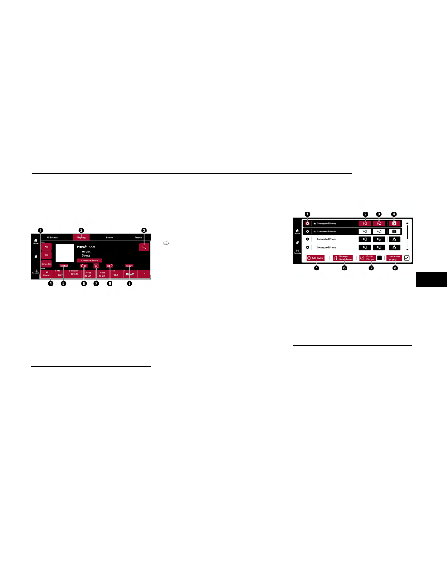
Passenger Screen Radio Mode

1 — Source Buttons
2 — Now Playing Tab
3 — Search Button
4 — Radio Presets
5 — Related Button
6 — Seek Down Button
7 — Direct Tune Button
8 — Seek Up Button
9 — Replay Button

Device Manager

1 — Device Settings
2 — Phone Connection
3 — Media Connection
4 — Apple CarPlay®/Android Auto™ Connection
5 — Add Device
6 — Manage Headphones
7 — Do Not Disturb
8 — Two Active Phones

MULTIMEDIA

209

5

To pair a set of Bluetooth® Headphones:

1. If viewing Device Manager in full screen, press the

Add Device button. If viewing Device Manager on the
Home screen, press “Pair Bluetooth® headphones”.

2. From the pop-up, press “Search For Headphones”.

The system will begin searching for the Bluetooth®
signal of your headphones.

3. Select the name of your headphones from the list of

possible devices. The system will connected to the
headphones.

NOTE:

The Passenger Screen will connect to previously paired
Bluetooth® headphones after Passenger Screen
activation.

Removing Bluetooth® Headphones

1. From the Controls screen, press the Manage Head-

phones button.

2. Press the Settings button (gear icon) next to the set

of headphones you wish to remove.

3. Press “Delete Device”; the Bluetooth® headphones

will be removed from the system.

NAVIGATION

Navigation allows you to assist the driver in searching
for destinations using Uconnect’s built-in Navigation
system. For information on the full functionality of Navi-
gation, refer to your Uconnect Radio Instruction
Manual.

When a new route is selected from the Passenger
Screen, a confirmation will be sent to the driver. The
driver will be able to confirm or deny the route.

NOTE:

Using Navigation on the Passenger Screen will not
affect the Navigation screen in the Uconnect system.
The Driver can continue to use Navigation while the
Passenger Screen can “suggest” new routes or stops.

CAMERA

Camera will display the equipped vehicle camera feed.
When selected, press the desired Camera button. The
feed from that camera will display in the center of the
touchscreen. Press the X button or Back Arrow button
to return to the Home screen.

NOTE:

The Passenger Screen will lose access to a camera if
the driver chooses to view it on the Uconnect system or
if a condition would activate the camera on the
Uconnect system (the rearview camera being activated
when the vehicle is shifted into REVERSE).

3RD PARTY APPS — IF EQUIPPED

If equipped, your vehicle may contain some 3rd party
apps, which will further enhance your Uconnect system.

McIntosh

McIntosh is a 3rd party app that can enhance your
Uconnect system’s media player. For the app to be
effective, there must be audio playback in the Uconnect
media player. McIntosh can control the playback of
audio as well as display the output level decibel meters.

To launch the app, begin playing audio and follow these
steps:

1. Press the Apps button.

2. Press the McIntosh app.

McIntosh

210

MULTIMEDIA

The McIntosh app will allow you to perform the following when listening to music:

NOTE:

The Seek feature will not work while using Bluetooth®.

Skip Backward

Press to skip backward. Press and hold to fast rewind.

Play/Pause

Press to play/pause the track.

Skip Forward

Press to skip forward. Press and hold to fast forward.

Repeat

Press to repeat track. Press again to repeat playlist. Press again to turn off (works only
with a USB device).

Change Channel Down

Press to change channel down. Press and hold to seek channel down. While using
AM/FM, pressing the channel down will change the frequency by 0.1. Pressing and
holding in AM/FM will seek channels.

Change Channel Up

Press to change channel up. Press and hold to seek channel up. While using AM/FM,
pressing the channel up will change the frequency by 0.1. Pressing and holding in
AM/FM will seek channels.

Menu

Press to access McIntosh settings.

About

Press to learn more about McIntosh.

Audio

Press to open the Audio Settings page of the Uconnect media player.

NOTE:

To change the source within the app, press the source
name. Pressing this will open a menu with all available
sources. To change the audio source outside of the
app, press the Media button, and then press the
Sources button.

To exit the app, press any of the buttons on the bottom
menu bar.

Day/Night Mode

Press the Menu button in the upper left-hand corner to
access McIntosh settings. Tap on a mode to set it as
the default, or tap “Auto Mode” to enable your screen to
automatically switch between Day and Night Modes.

Theater Mode

Press the Menu button in the upper left-hand corner to
access McIntosh settings. Under “Theater Mode”,
select “On” to bring forward the McIntosh Meters. This
will enlarge the meters for a more prominent view.

NOTE:

Theater Mode will engage after 10 seconds without
input from the user.

For more information on McIntosh, the McIntosh app
and its functionality, please visit
https://www.mcintoshlabs.com.

REAR SEAT ENTERTAINMENT (RSE) WITH
AMAZON FIRE TV BUILT-IN —
IF EQUIPPED

OVERVIEW

Rear Seat Entertainment with Fire TV built-in is
designed to give your family years of enjoyment.

Fire TV lets passengers enjoy a wide variety of content
from popular apps (subscriptions may be required).
Stream videos, play games, listen to music, get informa-
tion, and watch downloaded programs all while on the

MULTIMEDIA

211

5

road. Two Voice Remotes with Alexa are included with
the system. Press the Microphone button on the Voice
Remote with Alexa to easily find, launch, and control
content. Check sports scores, play music, control smart
home devices, or see your live camera feeds (compat-
ible smart home device required and sold separately).
In addition to streaming and downloaded content,
changing the input in Fire TV also enables you to:

Mirror what’s on your phone or tablet to Fire TV via
Miracast capable devices.

Stream your favorite shows with Fire TV.

Plug and play a variety of standard video games or
devices into the HDMI port.

Listen to audio over wired or wireless headphones
(not included, customer will have to provide their
own or play audio through in-cabin speakers with
Listen In feature in front seat).

Plug and play a variety of devices into the front seat
Video USB port. USB ports located under the rear
screens are charge only.

Watch content individually on each rear display or
mirror across both displays to watch together.

NOTE:

The vehicle must be in an active and usable cellular
range and properly equipped with a Uconnect 5 NAV
system and Rear Seat Entertainment with Fire TV pack-
age. Streaming requires a Wi-Fi connection and regis-
tered Amazon account to run Fire TV in the vehicle.
Streaming service subscriptions are not included. Ser-
vices and features are subject to change or withdrawal
at any time, may not be available in all areas and lan-
guages, and may require separate subscriptions.

Please review this Owner's Manual to become familiar
with RSE features and operation.

GETTING STARTED

1 — Rear Seat Entertainment (Rear Touchscreen)
2 — Headphone Jack
3 — USB C Charging Port
4 — HDMI Port
5 — Uconnect System (Front Touchscreen)

There are four different ways to operate the features of
Rear Seat Entertainment with Fire TV built-in:

Voice Remote with Alexa

Front radio screen

Passenger screen (if equipped)

Individual rear touchscreens for Rear Seat Enter-
tainment with Fire TV built-in touch on each rear
screen

For information on the front media hub USB/AUX ports

page 73.

ACCESSING REAR SEAT
ENTERTAINMENT WITH FIRE TV
BUILT-IN FROM THE FRONT RADIO
SCREEN

You can access your Rear Seat Entertainment with Fire
TV built-in system by following these steps:

Option 1

1. Press the Media button.

2. Press the Rear Seat button icon.

Option 2

1. Press the Apps button on the bottom of the

touchscreen.

2. Press the Uconnect Theater button on the touch-

screen. You may need to navigate to different pages in
the Apps drawer to find the Uconnect Theater button.

ACCESSING REAR SEAT
ENTERTAINMENT WITH FIRE TV
BUILT-IN FROM THE REAR
SCREENS

You can also access your Rear Seat Entertainment with
Fire TV built-in by choosing one of the following options:

Option 1

The system will automatically turn on when the
vehicle is started. Pushing the power button on the
Voice Remote with Alexa will turn the system back
on if it was manually shut off. If the screen is inac-
tive and goes to a screen saver, the system can be
woken up by either tapping the screen or pushing
any button on the Voice Remote with Alexa.

Rear Screen Entertainment for Uconnect 5/5 NAV

212

MULTIMEDIA

Option 2

Swiping on either of the rear touchscreens.

NOTE:

When using the rear screens, the system will launch
with Fire TV.

ACCESSING REAR SEAT
ENTERTAINMENT WITH FIRE TV
BUILT-IN FROM THE PASSENGER
SCREEN — IF EQUIPPED

You can also access Rear Seat Entertainment with Fire
TV built-in content from the Passenger Screen.

Follow these steps:

1. Access the Home screen for the Passenger Screen.

2. Swipe right on the Home screen and select Fire TV

Rear Seat Entertainment Controls.

FIRST TIME STARTING UP (USING
THE REAR SCREENS)

Boot-up Screen

When turning on the system for the first time from the
rear screens, a boot-up screen will appear on the sys-
tem displaying the Fire TV logo.

During this boot-up sequence, language options will be
available for the system.

Voice Remote with Alexa Pairing

After the boot-up sequence is complete, the system will
then give the option to pair a Voice Remote with Alexa
(two are included with the system).

Follow the on-screen instructions for how to pair a Voice
Remote with Alexa to the system. Two Voice Remotes
with Alexa are included to be paired with each rear
screen.

A Voice Remote with Alexa can be paired to each rear
screen. It will function with the rear screen it was paired
with. The pairing steps will need to be done for each
rear screen.

NOTE:

If the Voice Remote with Alexa pairing fails, on-screen
instructions will appear for trying to pair again.

Connecting to a Network

During the start-up process, the system will need to be
connected to a network to function. Multiple network
sources can be options for the system.

Some options for a network connection are:

Wi-Fi Hotspot using a capable smartphone (if acti-
vated, it will show as a possible network for the sys-
tem on the screen).

Outside connection like a home Wi-Fi network.

In-vehicle Wi-Fi.

NOTE:

When a network is connected to the system for the first
time, an over-the-air-software update will take place
using the Wi-Fi connection. It is recommended that an
unlimited Wi-Fi connection, if available, be used during
this update. After this first-time update, updates will
only occur when one is available.

Account Sign-in

The next step will be the option to sign in to your Ama-
zon account.

There are two options to sign into the system:

I already have an Amazon account:

Sign in with an

already existing Amazon account

I am new to Amazon:

Create a new Amazon Account

If “I am new to Amazon” is selected, follow the
on-screen steps to set up an Amazon account with the
system.

Parental Controls

Another feature that will appear during this first time
set up is parental controls.

When the parental controls page appears, it will give
the options “Enable Parental Controls” and “No Paren-
tal Controls”. If “Enable Parental Controls” is selected,
follow the on-screen steps to set up parental controls
for the system.

ALEXA VOICE CONTROL

A feature with Rear Seat Entertainment with Fire TV
built-in that enhances your experience is Alexa. It is
simple to get started using this feature. Push the Micro-
phone button at the top of the Voice Remote with Alexa
to activate Alexa and get started.

LISTEN VIA VEHICLE SPEAKERS

A feature within Rear Seat Entertainment with Fire TV
built-in is the front radio Listen feature. On the front
radio Home screen for Fire TV, select the Listen button
in the top right corner on either card for Screen 1 or 2.
This will allow you to have either rear screen play audio
through all the speakers in the vehicle.

MULTIMEDIA

213

5

QUICK MENU

Accessing the quick menu will give you more options for
Fire TV.

To access the quick menu, tap the screen and it will
appear. The quick menu is also accessible by pushing
the Gear/Settings button on the Voice Remote with
Alexa.

Some options of the quick menu are:

Power

— This will power the screen off.

On-Screen Remote

— This will bring up the

on-screen remote to use with the system.

Back

— This will let you go back a page.

Home

— This will take you to the Home screen.

Gear/Settings

— This will let you access certain set-

tings in the system. For more setting options, select
“Settings” within the on-screen Gear/Settings
menu.

Vehicle

— This will bring up the Vehicle menu. From

here you can adjust rear climate controls and the
Are We There Yet? app.

PARENTAL CONTROLS (USING THE
REAR SCREENS)

If parental controls were not set during the first time
start up of the system, they can be set by following
these steps:

1. Push the Gear/Settings button on the Voice Remote

with Alexa or tap the screen to access “Settings” in
the “quick menu”.

2. Select the Gear/Settings icon on the screen.

3. Select “Settings” on the screen.

4. While in Settings, select “Preferences”.

5. Select “Parental Controls”; from here you can turn

“Parental Controls” on or off and set up a PIN for the
controls using the Voice Remote with Alexa.

VOICE REMOTE WITH ALEXA
PAIRING (USING THE REAR
SCREENS)

If the Voice Remote with Alexa needs to be paired again
or a new remote is being paired, follow these
procedures:

1. Install batteries into the remote.

2. Tap the screen and Select the Gear/Settings icon on

the screen.

3. Select “Settings” on the screen.

4. In Settings, select “Controllers & Bluetooth®

Devices”.

5. From this menu, select “Add New Remote”.

6. Follow the on-screen steps for Voice Remote with

Alexa pairing.

A long press on the Home button can also re-pair a
Voice Remote with Alexa that has become
disconnected.

NOTE:

Your vehicle is included with two Voice Remotes with
Alexa. A Voice Remote with Alexa can be paired to each
rear screen. It will function with the rear screen it was
paired with. The pairing steps will need to be done for
each rear screen.

MEDIA SOURCES INPUT (USING
THE FRONT RADIO AND REAR
SCREENS)

Front Radio Screen

Users can select inputs for each rear screen from the
front radio touchscreen by selecting the Rear Seat tab
and choosing the desired content by selecting “Launch
Source” on the Screen 1 or Screen 2 tab.

Inputs available within Launch Source under “Inputs”
are “Fire TV”, “HDMI”, and “USB”.

Rear Screens

To select inputs on the rear screen, scroll down on the
Fire TV Home screen and select your desired input
under “Input”.

Inputs can also be selected from the Brand tab in the
top menu. While in this tab, scroll down to “Inputs” for
selection options.

NOTE:

The Brand tab naming in the top menu will depend on
the naming of the vehicle’s brand.

214

MULTIMEDIA

VOICE REMOTE WITH ALEXA

1.

Power Button

— Turns the screen for the selected

channel on or off.

2.

5-way Navigation Control

— This control has options

by pressing the Circle button Up, Down, Left, or
Right to navigate on-screen for selections and push-
ing the center button to confirm selections.

3.

Back

— Push to exit out of menus or return to the

previous screen.

4.

Home

— Push to return to the Fire TV Home screen.

5.

Seek Backward/Rewind Button

— Push and hold to

fast rewind through the current audio track or video
chapter. Push once to revert back to the previous
track.

6.

Volume

— Push the - button to decrease the volume

and + button to increase the volume.

7.

Channel Guide

— Push to access the channel guide

for the system.

8.

Mute

— Mutes headphone audio.

9.

Prime Video

— Push to launch Prime Video app.

10.

App 1

— Push to navigate to App 1.

11.

Microphone Button

— Push to activate Alexa.

12.

Menu

— Push to access the Fire TV menu.

13.

Seek Forward Button

— Push and hold to fast for-

ward through the current audio track or video
chapter. Push once to skip to the next track.

14.

Play/Pause Button ||

— Begin/resume or pause

disc play.

15.

Channel +/-

— Push the up or down arrow button

on the Channel button to browse channels avail-
able in Fire TV.

16.

Recent

— Push to access recently viewed content

on Fire TV.

17.

Gear/Settings

— Push to bring up setting options

for Fire TV.

18.

App 2

— Push to launch App 2.

19.

Vehicle Button

— Push to activate the Vehicle

menu.

REPLACING THE VOICE REMOTE
WITH ALEXA BATTERIES

Each Voice Remote with Alexa requires two AAA batter-
ies for operation.

To replace the batteries:

1. Locate the battery compartment on the back of the

Voice Remote with Alexa, then slide the battery
cover downward.

2. Remove the old batteries and follow battery recy-

cling procedures for your area.

3. Install new batteries, making sure to orient them

according to the polarity diagram shown inside the
battery compartment.

4. Slide the battery compartment cover back on.

REAR SEAT ENTERTAINMENT WITH
FIRE TV BUILT-IN STREAMING
(USING THE FRONT RADIO AND
REAR SCREENS)

Access Using Launch Source

To access Rear Seat Entertainment with Fire TV built-in
from the front radio, press the Media tab located on the
bottom menu bar. Then select the Rear Seat option
located on the top menu bar. Select “Launch Source”,
and then under “Inputs” select “Fire TV Home”.

Voice Remote with Alexa

MULTIMEDIA

215

5

Access Using Browse Media

Selecting “Browse Media” on the front radio screen will
give access to different media within Rear Seat Enter-
tainment with Fire TV built-in.

These options will be in the top menu of “Browse
Media” and include:

Fire TV

— Selecting “Fire TV” will show streaming

options for categories and to select apps. This
option will be selectable on the left slider menu in
“Browse Media”. While in “Browse Media” under
Fire TV, it will display recent activity under “Recent”.
This will display recent videos viewed from Fire TV
and recent downloads as well.

USB Video

— Under “USB Videos”, videos will appear

that are options with a USB device connected to
Rear Seat Entertainment with Fire TV built-in.

USB Music

— Under “USB Music”, music will appear

that are options with a USB device connected to
Rear Seat Entertainment with Fire TV built-in.

Access Using the Voice Remote with Alexa and Rear
Screens

Rear passengers will be able to access some options
for streaming by pressing the “Prime Video”, “App 1”, or
“App 2” button on the Voice Remote with Alexa. Select-
ing one of those buttons on the Voice Remote with
Alexa will take you to the home page for that respective
streaming service. Turning on either of the rear screens
will launch Fire TV. By default, the rear screens will
always launch in Fire TV. More streaming options can
be selected on the Fire TV home page.

Fire TV

Fire TV is your source for online streaming with Rear
Seat Entertainment with Fire TV built-in.

NOTE:

A data source needs to be connected to the system for
streaming to be accessible. This can be set up when
Fire TV is turned on for the first time on the rear
screens. Some options can be an in-vehicle 4G Wi-Fi
hot spot, capable Wi-Fi hot spot from a mobile device,
or Wi-Fi from an outside source like a home or a garage.

To access Fire TV on the front screen, select “Launch
Source” on the front touchscreen, Rear Seat screen
and then “Fire TV Home” under “Inputs”.

Viewing from the front radio screen or passenger
screen mirrors or controls the Fire TV experience from
one of the rear Fire TV displays.

The menu bar for Fire TV will have the options for
“Home”, “Find”, “Library”, “Brand”, and “Live”.

Below the menu bar will be streaming options linked to
your Prime account like “Prime Video”.

The front radio screen offers some options:

Power

— This will turn Fire TV on or off.

Screen 1 and Screen 2 Toggle

— This toggles

between the Rear Screens (for use with front radio
screen only).

Collapse

— While viewing on the front radio screen,

this will collapse the screen to dashboard view.

Source Drawer

— This will open the “Source Drawer”

and the source logo will be displayed on the icon.

Browse Media

— This will open the “Browse Media”

pop-up.

Back

— This will let you go back the previous page.

Fire TV Home

— This will take you back to the Fire

TV home page.

Menu

— This will open the Fire TV menu.

Remote icon

— This will display the on-screen

remote.

NOTE:

Front radio screen mirroring and watching can only be
done when the vehicle is in PARK. The vehicle must be
in an active and usable cellular range and properly
equipped with a Uconnect 5 NAV system and Rear Seat
Entertainment with Fire TV package. For streaming, a
Wi-Fi connection and registered Amazon account are
required to run Fire TV in the vehicle. Streaming service
subscriptions are not included. Services and features
are subject to change or withdrawal at any time, may
not be available in all areas and languages, and may
require separate subscriptions.

FIRE TV APPS/GAMES
(USING THE REAR SCREENS)

Apps and games can be accessed using Rear Seat
Entertainment with Fire TV built-in.

To access Apps on the rear screen, turn on the system
and select “Find” in the top menu. On the Find page,
select “Appstore”. Within the App Store® you can pur-
chase apps and games. From here you can also select
from all the apps and games that have been
purchased.

USING THE VIDEO USB PORT

Plug in a USB drive or mass storage device and play
your favorite music or movies.

NOTE:

To view USB media on the rear screens, insert a USB
drive into the port. The USB drive port is located under
the radio controls in the instrument panel.

On the rear screen you can browse the content of the
USB device by going to the USB source in the inputs.
Use the search feature to find your media faster.

216

MULTIMEDIA

PLAY VIDEO GAMES

Connect the video game console to either of the HDMI
ports located behind either of the first row seats.

NOTE:

Certain high-end video games may exceed the power
limit of the vehicle's Power Inverter

page 77.

HEADPHONES OPERATION

Rear Seat Entertainment with Fire TV built-in does not
come equipped with headphones. Customers will need to
provide their own wireless headphones that can be paired
with the system using Bluetooth®. Customers can also
use their own wired headphones and plug them into a
Headphone Jack located under one of the rear screens.

Wireless Headphones Pairing

To pair wireless headphones with Rear Seat Entertain-
ment with Fire TV built-in using the rear screens, follow
these steps:

1. Push the Gear/Settings button on the Voice Remote

with Alexa or tap the screen.

2. Select the Gear/Settings icon on the screen.

3. Select “Settings” on the screen.

4. While in Settings, select “Controllers & Bluetooth®

Devices”.

5. Select “Other Bluetooth® Devices” and follow the

on-screen steps for pairing.

While multiple headphones can be paired, only one will
output audio at a time.

REAR CLIMATE CONTROLS

The Rear Climate Controls can also be controlled using
Rear Seat Entertainment with Fire TV built-in

page 62.

Rear Climate Controls can be accessed by using the
Vehicle menu. Tap on either rear screen and select the
Vehicle icon or press the Vehicle button on the Voice
Remote with Alexa. Then select the Rear Climate Con-
trols option.

Options within Rear Climate Controls are:

Icon

Description

ON

Climate Control ON Button

Press and release this button to turn the Rear Climate Controls on.

OFF

Climate Control OFF Button

Press and release this button to turn the Rear Climate Controls off.

SYNC

SYNC Button

Pressing this button will sync both sides of the Rear Climate Controls.

AUTO Button

Automatically controls the rear interior cabin temperature by adjusting airflow distribution and amount. Toggling this function will cause the system to switch
between Manual mode and Automatic mode.

Headphone Jack/HDMI/USB

1 — Headphone Jack (Headphone Output Only)
2 — USB Port (Charge Only)
3 — HDMI Port

MULTIMEDIA

217

5

Icon

Description

Rear Passenger Temperature Up and Down Buttons

Provides the rear passengers with independent temperature control. Press the button on the touchscreen to increase or decrease the temperature. The tem-
perature will get warmer as you move up toward the red arrow and colder as you move down toward the blue arrow.

Headliner Mode

Headliner Mode

Air comes from the outlets in the headliner. Each of these outlets can be individually adjusted to direct the flow of air. Moving the air vanes of the outlets to
one side will shut off the airflow.

Mode Control

Mode Control Button On The Instrument Panel

The airflow distribution mode can also be selected by pushing the hard toggle switch on the instrument panel, below the radio screen. Pushing this toggle
switch down will cycle through the seven mode combinations in order: Face, Face/Feet, Feet, Windshield/Feet, Windshield, Windshield/Face, and Windshield/
Face/Feet. The cycle will repeat if the button is continually pushed.

Floor Mode

Floor Mode

Air comes from the floor outlets.

1,2,3, etc.

Blower Control

Blower Control is used to regulate the amount of air forced through the Climate system. There are seven blower speeds available. Adjusting the blower will
cause Automatic mode to switch to Manual operation.

218

MULTIMEDIA

LEGAL & COMPLIANCE

To access Legal and Compliance information about
Rear Seat Entertainment with Fire TV built-in from the
rear screens, follow these steps:

1. Push the Gear/Settings button on the Voice Remote

with Alexa or tap the screen.

2. Select the Gear/Settings icon on the screen.

3. Select “Settings” on the screen.

4. While in the Settings menu, select “My Fire TV” and

then “Legal & Compliance”.

OFF-ROAD PAGES — IF EQUIPPED

Your vehicle may be equipped with Off-Road Pages,
which provides the vehicle status information while
operating on off-road conditions. It supplies information
relating to the vehicle ride height, the status of the
transfer case, the pitch and roll of the vehicle, and the
active Selec-Terrain Mode.

To access Off-Road Pages, press the Off Road button
on the touchscreen from the Vehicle menu, and then
press “Launch Off-Road”.

Off-Road Pages has the following selectable pages:

Vehicle Dynamics

Accessory Gauges

Pitch & Roll

Selec-Terrain — If Equipped

Suspension — If Equipped

NOTE:

With a Connected Services subscription, you can record
your Off-Road data and send it directly to the mobile
app. Press the Record button to begin.

OFF-ROAD PAGES STATUS BAR

The Off-Road Pages Status Bar is located along the bot-
tom of Off-Road Pages and is present on each of the
selectable page options. It provides continually updat-
ing information for the following items:

Current Transfer Case Status

Current Selec-Terrain mode

Current Latitude/Longitude

Current Altitude of the vehicle

Status of Hill Descent

Hill Descent Control or Selec-Speed Control Selected
Speed in mph (km/h).

VEHICLE DYNAMICS

The Vehicle Dynamics page displays information con-
cerning the vehicle’s drivetrain.

The following information is displayed:

Steering angle in degrees

Status of Transfer Case

Status of the Rear Axle Locker — If Equipped

Status Bar

1 — Transfer Case Status
2 — Current Latitude/Longitude
3 — Current Altitude
4 — Hill Descent Control

Vehicle Dynamics Menu

1 — Vehicle Dynamics
2 — Steering Angle
3 — Transfer Case
4 — Rear Axle Status

MULTIMEDIA

219

5

ACCESSORY GAUGES

The Accessory Gauges page displays the current status
of the vehicle’s Coolant Temperature, Oil Temperature,
Oil Pressure, Transmission Temperature, and Battery
Voltage.

PITCH & ROLL

The Pitch & Roll page displays the vehicle’s current
pitch (angle up and down) and roll (angle side to side)
in degrees. The Pitch & Roll gauges provide a visualiza-
tion of the current vehicle angle.

SELEC-TERRAIN — IF EQUIPPED

The Selec-Terrain page displays the current Selec-
Terrain Mode through a high resolution image. Adjust-
ing the Selec-Terrain Mode will alter the image on the
screen. The vehicle must be in the ON/RUN position to
display Selec-Terrain information.

The selectable modes are as follows:

Rock — Vehicle Must Be In 4WD Low

Sand/Mud

Snow

Auto — Default

Sport

NOTE:

The Off-Road Pages Status Bar will also display the cur-
rent Selec-Terrain Mode.

SUSPENSION — IF EQUIPPED

The Suspension page displays information concerning
the vehicle’s suspension.

The following information is displayed:

Wheel Articulation

Current Ride Height Status

Off-Road 2

Off-Road 1

Normal

Aero

Entry/Exit

Accessory Gauges Menu

1 — Coolant Temperature
2 — Oil Temperature
3 — Oil Pressure
4 — Transmission Temperature
5 — Battery Voltage

Pitch & Roll Menu

1 — Current Pitch
2 — Current Roll

220

MULTIMEDIA

NOTE:

The wheel articulation will be represented by a yellow
color in the Wheel Articulation. If Ride Height is
adjusted, the Ride Height indicator on the screen will
switch to the appropriate height and the Wheel Articula-
tion will show the movement and change in height.

TRAIL RECORDING — IF EQUIPPED

Overview

The Trail Recording feature can be accessed from a
variety of different ways: within the Vehicle Dashboard
screen or within the Off-Road Pages. There will be
options within “Trail Recording” where you can start
recording your trail or view saved recordings where you
can see previous trails recorded.

Recording A Trail And Stop Recording

To start recording a trail, select “Start Recording”
towards the bottom of the touchscreen. Once selected,
your trail will start recording for as long as desired.

When the trail is over, press “Stop Recording”. Select
whether to save the trail in which the trail will be saved
and will appear in “Saved Recordings”. Selecting “Can-
cel” will not save the trail, and the trail will be deleted.

NOTE:

After 30 miles (48 km) a notification will appear on the
touchscreen asking if you want to keep recording.

Adding a Waypoint

On the bottom left-hand side of the touchscreen select
“Add Waypoint” from the trail recording screen. This will
allow the user to pin a location along the trail, both dur-
ing and after the recording. There are three selectable
options to mark a Waypoint: a Waypoint can be placed
whether the vehicle is in or out of motion, but can only
be edited when the vehicle is not moving. As a default,
Waypoints are named chronologically in the order in
which the Waypoints are marked or added. They can be
renamed later by pressing the edit icon located to the
right of the defaulted Waypoint name.

Places

Obstacle

Guidance

NOTE:

A Waypoint can be placed whether or not the vehicle is
in motion, but can only be edited when the vehicle is
not moving.

Expand/Collapse View

While in the Trail Recording screen, press the Expand
button located to the right of the Map View to enlarge
the Trail Map screen during recordings. Once in
expanded view, press the collapse icon which will
shrink the trail map during screen recordings.

Editing A Trail

After finishing recording a trail, there will be a scale to
rate the difficulty of the trail for future reference. The
scale is from 1-10 with one being the easiest and
10 being the most difficult.

NOTE:

Setting the difficulty is not required to save the trail and
can be edited afterwards.

Editing/Deleting a Waypoint

To edit a Waypoint, select the desired Waypoint on the
map. Once selected, choose the type of Waypoint. Once
selected, choose a sub-type that describes the Waypoint.
Waypoint sub-types are listed in the following table. Once
the Waypoint has been edited, press the Save button.

To delete the Waypoint, select the desired Waypoint on
the map, then press the Delete Waypoint button.

POI

Obstacles

Guidance

Camping

Mud

Bare Left

Scenic View

Rock

Bare Right

Staging Area

Sand

Dead End

Trailhead

Steep Ascent

Hard Left

Water

Steep Descent

Hard Right

Water

Slow

Route Closure

Suspension Menu

1 — Wheel Articulation
2 — Current Ride Height

MULTIMEDIA

221

5

Waypoints can be renamed later by pressing the pencil
icon located to the right of the defaulted Waypoint
name. Selecting the pencil icon will bring up a keyboard
which will allow you to customize the Waypoint name.

NOTE:

Editing Waypoints is not available while the vehicle is in
motion. To edit and customize Waypoints, the vehicle
must not be in motion.

If you want to delete a Waypoint, select the Waypoint
that you created and press the Delete Waypoint button
located towards the bottom of your touchscreen. The
pop-up, “Your waypoint was deleted successfully” will
appear on your touchscreen once the Waypoint was
successfully deleted.

Saving And Canceling A Trail

When finished editing a trail, select “Save”. The trail will
be stored in the Saved Recordings tab.

Selecting “Cancel” will delete the trail, and a pop-up
screen will appear asking if you are sure that you want
to cancel your current trail recording. Selecting “No,
Don’t Cancel” or the X button will take you back to the
Waypoint editing screen. Selecting “Yes, Cancel” will
discard the selected trail recording.

Saved Trails

To view previously saved trails, click the Saved Record-
ings button on the Trail Recording home page. Once
entering Saved Recordings, a list of previously saved
trails will be listed. The Remove Icon button to the far
right of each trail will delete the trail. To delete all trails,
select “Delete All” towards the bottom of the
touchscreen.

NOTE:

Saved recordings can be accessed even once the Brand
connect services subscription has expired.

After selecting a saved recording, options will be avail-
able to view, edit, delete, or export the recording onto a
USB device. Pressing “View Performance Data” will
showcase the vehicle’s pitch, roll, altitude, and location
for each selected Waypoint. A Snapshot feature is avail-
able, where a photo of the performance data can be
exported to a connected USB device.

Export a Recording onto a USB

After selecting a saved recording, press the Export but-
ton towards the bottom of the touchscreen and select
the USB icon option. There will be a pop-up message
afterwards stating whether or not the export was
successful.

ADVENTURE GUIDES — IF EQUIPPED

To access the Adventure Guides feature, press the Vehicle
icon on the lower menu bar of your touchscreen. From the
Vehicle Dashboard, press “Adventure Guides”.

To search for an off-road trail:

1. Press the search box and enter an address or

keyword.

NOTE:

An active subscription to Brand Connect con-
nected services is required to access the Adven-
ture Guides feature. If you do not have an active
subscription, click the Register button on the
touchscreen and follow the prompts.

If there is no network connection, a message will
display on your touchscreen, “Data connection
temporarily not available. Please try again later.”
Press “OK”, and ensure there is a stable network
connection.

If there are no search results within the area in
which you added the address or keyword, the
message “No Results Found” will display on your
touchscreen.

Adventure Guides App

Search For An Off-Road Trail

222

MULTIMEDIA

2. The distance to each search result will appear on

the left of each destination. The difficulty level of
each trail will show towards the right of each desti-
nation. Select the trail you wish to navigate to.

NOTE:

Press the Map View button to view an expanded
summary of each trail and its difficulty level.

NOTE:

Each trail detail screen will provide you information
such as an address, phone number, typical open/
close times, and vehicle requirements.

3. Press the Preview Trail button to view the trail info.

Press the Start Recording button which will bring
you to the Off Road Pages screen where you will be
able to save the recording, view saved recordings,
and see the distance to your destination.

NOTE:

Pressing the Back arrow on the Trail Info page will
bring you back to the trail detail screen.

4. Press the Navigate To Trail button which will send

the directions to your TomTom Navigation system.

Trail Difficulty

Map View Button

Expanded Trail Difficulty View

Preview Trail

Navigate To Trail

MULTIMEDIA

223

5

5. If the trail does not exist within your Uconnect sys-

tem’s local memory, press the Download button. If
the trail already exists, meaning it has already been
downloaded at some point, press the Check For
Updates button.

NOTE:

“Trail Updated Successfully” will display towards
the top of your touchscreen if the trail update
was completed properly. If “Trail could not
update. Not enough space” appears, you will
need to clear up space under your “Downloaded
Trails” by removing trails that are no longer
needed or desired. “No Updates available”
means the trail you have selected is up-to-date.

Pressing “X” on any of these screens will take
you back to the trail details screen.

Trails Near You

Press the Trails Near You button to show the first
20 trails based on 500 miles (805 km) within your cur-
rent vehicle’s location.

NOTE:

If there are no trails within a 500-mile (805-km) radius
within your current vehicle’s location, “No Results
Found” will appear on your touchscreen.

Preloaded Trails

Press “Preloaded Trails” to see a list of trails that are
preloaded onto your Uconnect system.

NOTE:

“Preloaded Trails” cannot be deleted from the list, as
they are the default trails that remain on your system
permanently.

Downloaded Trails

Any trail that you wish to download, press the Download
button on the trail you have selected.

NOTE:

“Trail Downloaded Successfully” will display towards
the top of your touchscreen if the trail was down-
loaded properly. Once the download has been suc-
cessful, “Check for updates” will be available if you
wish to check the trail for updates.

“Downloaded Trails Full. Free up some space” will
display towards the top of your touchscreen if there
is not enough space. Press the Downloaded Trails
button to remove existing trails.

Press the Remove icon to remove a trail from the list.
You will be presented with a confirmation, “Are you sure
you want to delete this trail?”. Press “Yes” to show the
trail was deleted successfully, or press “No” or the X
button which will bring you back to the Downloaded
Trails list.

Preloaded Trails

Remove Downloaded Trails

224

MULTIMEDIA

TRAILER TOW — IF EQUIPPED

If your vehicle is equipped with Trailer Tow Pages, you
will be able to view and edit different trailer settings for
each of your unique trailers.

To access Trailer Tow Pages, press on the Vehicle icon
in the lower menu bar on the touchscreen, and then
select “Towing & Trailers”.

TRAILER INFO

The Trailer Info main page displays your trailer’s tire
pressure, odometer, electric range select, and view of
your trailer’s Tow/Haul mode status.

Displayed in the Trailer Info tab are the following gauges
that show information for each separate trailer:

Trailer Brake

Transmission Temperature

Coolant Temperature

Oil Temperature

Oil Pressure

Battery Voltage

NOTE:

Press the Up and Down arrows on the right-hand side of
your touchscreen to toggle between gauges, as only up
to five will be displayed at a time.

The upper right-hand corner of each gauge will give you
the option to maximize each gauge, which will show you
the Gauge Detail View page that will show specific
gauge information and a status graph of the gauge over
time. To get back to the Trailer Info page, select the
same icon located at the top right.

NOTE:

If any gauge reaches a critical condition, the fill bar,
numerical readout, and icon will be displayed in bright red.

CAMERAS

Selecting the Camera tab within “Trailer Tow Pages” will
redirect you to the Trailer tab in the More Cams section
of the Camera app.

After selecting your desired trailer camera view, selecting
the More Cams button will take you back to the previous
screen.

In order for the camera’s features to be accessible, the
Surround View Camera settings have to be enabled

page 193.

Towing & Trailers Button

Trailer Tow Pages Info Tab

Trailer Tow Pages Camera Tab

MULTIMEDIA

225

5

LIGHT CHECK

Pressing the Light Check tab will open the Light Check
Ready page. A box will appear with the text “Activate
Light Check”, which will allow you to check your trailer’s
brake lights.

Once selected, the screen will change to “Light Check
in Progress”. The box will turn red and the text will read
“Cancel Light Check”, which will then turn the trailer’s
brake lights back off.

Checking “Auto Trailer Light Check” in the “Trailer
Brake/Trailer” Uconnect Settings will automatically turn
on your trailer’s lights once the trailer is attached to the
vehicle. For more information

page 192.

NOTE:

After two minutes, if “Cancel Light Check” is not
selected, the screen will automatically revert back to
the Activate Light Check screen.

SETUP

After selecting your trailer of choice, selecting the Setup
tab will redirect to the Uconnect Settings “Trailer Brake/
Trailer” feature,

page 192.

NOTE:

Make sure that “Use this Trailer” is selected in order to
make any settings changes to that selected trailer.

RADIO OPERATION AND MOBILE PHONES

Under certain conditions, the mobile phone being on in
your vehicle can cause erratic or noisy performance
from your radio. This condition may be lessened or
eliminated by repositioning the mobile phone within the
vehicle. This condition is not harmful to the radio. If
your radio performance does not satisfactorily improve
from repositioning the mobile phone, it is recom-
mended that the volume be turned down or off during
mobile phone operation when not using the Uconnect
system.

REGULATORY AND SAFETY
INFORMATION

US/CANADA

Exposure to Radio Frequency Radiation

The radiated output power of the internal wireless radio
is far below the FCC and IC radio frequency exposure
limits. Nevertheless, the wireless radio will be used in
such a manner that the radio is 8 inches (20 cm) or
further from the human body.

The internal wireless radio operates within guidelines
found in radio frequency safety standards and recom-
mendations, which reflect the consensus of the scien-
tific community.

The radio manufacturer believes the internal wireless
radio is safe for use by consumers. The level of energy
emitted is far less than the electromagnetic energy
emitted by wireless devices such as mobile phones.
However, the use of wireless radios may be restricted in
some situations or environments, such as aboard air-
planes. If you are unsure of restrictions, you are encour-
aged to ask for authorization before turning on the wire-
less radio

page 351.

Trailer Tow Pages Light Check Tab

Trailer Tow Pages Setup Tab

226

MULTIMEDIA

SAFETY

SAFETY FEATURES

ANTI-LOCK BRAKE SYSTEM (ABS)

The ABS provides increased vehicle stability and brake
performance under most braking conditions. The sys-
tem automatically prevents wheel lock and enhances
vehicle control during braking.

The ABS performs a self-check cycle to ensure that the
ABS is working properly each time the vehicle is started
and driven. During this self-check, you may hear a slight
clicking sound as well as some related motor noises.

The ABS is activated during braking when the system
detects one or more wheels are beginning to lock. Road
conditions such as ice, snow, gravel, bumps, railroad
tracks, loose debris, or panic stops may increase the
likelihood of ABS activation(s).

You also may experience the following normal charac-
teristics when the ABS activates:

ABS motor noise or clicking sounds (you may con-
tinue to hear for a short time after the stop).

Brake pedal pulsations.

A slight drop of the brake pedal at the end of the
stop.

The ABS is designed to function with the Original Equip-
ment Manufacturer (OEM) tires. Modification may result
in degraded ABS performance.

WARNING!

The ABS contains sophisticated electronic equip-
ment that may be susceptible to interference
caused by improperly installed or high output radio
transmitting equipment. This interference can
cause possible loss of anti-lock braking capability.
Installation of such equipment should be per-
formed by qualified professionals.

Pumping of the Anti-Lock Brakes will diminish their
effectiveness and may lead to a collision. Pumping
makes the stopping distance longer. Just press
firmly on your brake pedal when you need to slow
down or stop.

The ABS cannot prevent the natural laws of physics
from acting on the vehicle, nor can it increase
braking or steering efficiency beyond that afforded
by the condition of the vehicle brakes and tires or
the traction afforded.

The ABS cannot prevent collisions, including those
resulting from excessive speed in turns, following
another vehicle too closely, or hydroplaning.

The capabilities of an ABS equipped vehicle must
never be exploited in a reckless or dangerous man-
ner that could jeopardize the user’s safety or the
safety of others.

Anti-Lock Brake System (ABS) Warning

Light

The yellow ABS Warning Light will turn on when the igni-
tion is placed in the ON/RUN mode and may stay on for
as long as four seconds.

If the ABS Warning Light remains on or comes on while
driving, it indicates that the anti-lock portion of the brake
system is not functioning and that service is required.
However, the conventional brake system will continue to
operate normally if the ABS Warning Light is on.

If the ABS Warning Light is on, the brake system should
be serviced as soon as possible to restore the benefits
of Anti-Lock Brakes. If the ABS Warning Light does not
come on when the ignition is placed in the ON/RUN
mode, have the light repaired as soon as possible.

REAR SEAT REMINDER ALERT
(RSRA)

RSRA alerts of the possible presence of an object, pas-
senger, or pet in the rear seats through a visual and
auditory notification. When the system is activated, it
displays the message “Check Rear Seat” on the instru-
ment cluster display and sounds an auditory alert upon
the driver placing the ignition in the OFF position to exit
the vehicle. The system will activate automatically if a
rear door is opened within 10 minutes of the ignition
being placed in the ON/RUN position. RSRA should be
used as a reminder to check the rear seats; it does not
directly detect objects, passengers, or pets and is only
activated when the previous conditions are met.

To enable or disable RSRA, see

page 182.

227

6

WARNING!

Before exiting a vehicle, always come to a com-
plete stop, then shift the automatic transmission
into PARK and apply the parking brake.

Always make sure the keyless ignition node is in
the OFF position, key fob is removed from the
vehicle and vehicle is locked.

Never leave children alone in a vehicle, or with
access to an unlocked vehicle. Leaving children in
a vehicle unattended is dangerous for a number of
reasons. A child or others could be seriously or
fatally injured. Children should be warned not to
touch the parking brake, brake pedal or the gear
selector.

Do not leave children or animals inside parked
vehicles in hot weather. Interior heat buildup may
cause serious injury or death.

DROWSY DRIVER DETECTION
(DDD) — IF EQUIPPED

DDD detects when the driver is feeling fatigued and
warns the driver to pull over and take a break.

To Activate/Deactivate

DDD can be activated and deactivated through the
Uconnect system by selecting the following in order:

1. “Safety & Driving Assistance”

2. “Drowsy Driver Detection”

WARNING!

The DDD system is an aid for driving and does not
relieve the driver of the responsibility of driving the
vehicle. If you experience fatigue while driving, pull
over safely for a break without waiting for the DDD to
intervene. Only return to the road when you are in the
right physical and mental condition to prevent endan-
gering yourself and other drivers.

System Intervention

Using feedback obtained from the driver’s steering pat-
terns, any buttons/switches that are pressed, and from
the front camera, the system implements two operating
logics:

The first operating logic takes the driving style into
account, observing the road and detecting to what
extent the driver can continue driving with few lane
crossing events.

The second operating logic measures the time
spent behind the wheel with the vehicle speed
above 40 mph (60 km/h) and below 100 mph
(160 km/h).

If the driving style indicates that the driver is unable to
follow the road trajectory and respect the horizontal
lane markings while within the operating speed range
of the system, a pop-up will display on the instrument
cluster display suggesting the driver stop for a break.
An audible signal will also sound.

If the driver

accepts

the suggestion provided by the sys-

tem by pushing the “OK” button on the left side of the
steering wheel, the message will disappear from the
display.

If the driver

does not acknowledge

the warning it will

be displayed for 60 seconds and then disappear.

NOTE:

In the event of a DDD system failure, a dedicated mes-
sage will appear in the instrument cluster display.

ELECTRONIC BRAKE CONTROL
(EBC) SYSTEM

Your vehicle is equipped with an advanced EBC system.
This system includes the Anti-Lock Brake System (ABS),
Brake Assist System (BAS), Electronic Brake Force Dis-
tribution (EBD), Electronic Stability Control (ESC), Elec-
tronic Roll Mitigation (ERM), Hill Start Assist (HSA),
Intersection Collision Assist (ICA), and Traction Control
System (TCS). These systems work together to enhance
both vehicle stability and control in various driving
conditions.

Your vehicle may also be equipped with Dynamic Steer-
ing Torque (DST), Rain Brake Support (RBS), Ready
Alert Braking (RAB), and Trailer Sway Control (TSC).

DDD Warning Message

228

SAFETY

Brake Assist System (BAS)

The BAS is designed to optimize the vehicle’s braking
capability during emergency braking maneuvers. The
system detects an emergency braking situation by
sensing the rate and amount of brake application and
then applies optimum pressure to the brakes. This can
help reduce braking distances. The BAS complements
the Anti-Lock Brake System (ABS). Applying the brakes
very quickly results in the best BAS assistance. To
receive the benefit of the system, you must apply con-
tinuous braking pressure during the stopping sequence
(do not “pump” the brakes). Do not reduce brake pedal
pressure unless braking is no longer desired. Once the
brake pedal is released, the BAS is deactivated.

WARNING!

The Brake Assist System (BAS) cannot prevent the
natural laws of physics from acting on the vehicle, nor
can it increase the traction afforded by prevailing
road conditions. BAS cannot prevent collisions,
including those resulting from excessive speed in
turns, driving on very slippery surfaces, or hydroplan-
ing. The capabilities of a BAS-equipped vehicle must
never be exploited in a reckless or dangerous man-
ner, which could jeopardize the user's safety or the
safety of others.

Brake System Warning Light

The red Brake System Warning Light will turn on when
the ignition is placed in the ON/RUN mode and may
stay on for as long as four seconds.

If the Brake System Warning Light remains on or comes
on while driving, it indicates that the brake system is
not functioning properly and that immediate service is
required. If the Brake System Warning Light does not
come on when the ignition is placed in the ON/RUN
mode, have the light repaired as soon as possible.

Electronic Brake Force Distribution

(EBD)

EBD manages the distribution of the braking torque
between the front and rear axles by limiting braking
pressure to the rear axle. This is done to prevent over-
slip of the rear wheels to avoid vehicle instability, and to
prevent the rear axle from entering ABS before the front
axle.

Electronic Roll Mitigation (ERM)

ERM anticipates the potential for wheel lift by monitor-
ing the driver’s steering wheel input and the speed of
the vehicle. When ERM determines that the rate of
change of the steering wheel angle and vehicle’s speed
are sufficient to potentially cause wheel lift, it then
applies the appropriate brake and may also reduce
engine power to lessen the chance that wheel lift will
occur. ERM can only reduce the chance of wheel lift
occurring during severe or evasive driving maneuvers; it
cannot prevent wheel lift due to other factors, such as
road conditions, leaving the roadway, or striking objects
or other vehicles.

NOTE:

ERM is disabled any time the ESC is in “Full Off” mode
(if equipped). See

page 229 for a complete expla-

nation of the available ESC modes.

WARNING!

Many factors, such as vehicle loading, road condi-
tions and driving conditions, influence the chance
that wheel lift or rollover may occur. ERM cannot pre-
vent all wheel lift or rollovers, especially those that
involve leaving the roadway or striking objects or
other vehicles. The capabilities of an ERM-equipped
vehicle must never be exploited in a reckless or dan-
gerous manner which could jeopardize the user's
safety or the safety of others.

Electronic Stability Control (ESC)

ESC enhances directional control and stability of the
vehicle under various driving conditions. ESC corrects
for oversteering or understeering of the vehicle by
applying the brake of the appropriate wheel(s) to assist
in counteracting these conditions. Engine power may
also be reduced to help the vehicle maintain the
desired path.

Oversteer — when the vehicle is turning more than
appropriate for the steering wheel position.

Understeer — when the vehicle is turning less than
appropriate for the steering wheel position.

ESC uses sensors in the vehicle to determine the
vehicle path intended by the driver and compares it to
the actual path of the vehicle. When the actual path
does not match the intended path, ESC applies the
brake of the appropriate wheel to assist in counteract-
ing the oversteer or understeer condition.

The ESC Activation/Malfunction Indicator Light located
in the instrument cluster will start to flash as soon as
the ESC system becomes active. The ESC Activation/
Malfunction Indicator Light also flashes when the Trac-
tion Control System (TCS) is active. If the ESC

SAFETY

229

6

Activation/Malfunction Indicator Light begins to flash
during acceleration, ease up on the accelerator and
apply as little throttle as possible. Be sure to adapt your
speed and driving to the prevailing road conditions.

WARNING!

Electronic Stability Control (ESC) cannot prevent
the natural laws of physics from acting on the
vehicle, nor can it increase the traction afforded by
prevailing road conditions. ESC cannot prevent
accidents, including those resulting from excessive
speed in turns, driving on very slippery surfaces, or
hydroplaning. ESC also cannot prevent accidents
resulting from loss of vehicle control due to inap-
propriate driver input for the conditions. Only a
safe, attentive, and skillful driver can prevent acci-
dents. The capabilities of an ESC equipped vehicle
must never be exploited in a reckless or dangerous
manner which could jeopardize the user’s safety or
the safety of others.

Vehicle modifications, or failure to properly main-
tain your vehicle, may change the handling charac-
teristics of your vehicle, and may negatively affect
the performance of the ESC system. Changes to
the steering system, suspension, braking system,
tire type and size or wheel size may adversely
affect ESC performance. Improperly inflated and
unevenly worn tires may also degrade ESC perfor-
mance. Any vehicle modification or poor vehicle
maintenance that reduces the effectiveness of the
ESC system can increase the risk of loss of vehicle
control, vehicle rollover, personal injury and death.

ESC Operating Modes

Depending upon model and mode of operation, the ESC
system may have multiple operating modes.

ESC On

This is the normal operating mode for the ESC. When-
ever the vehicle is started, the ESC system will be in
this mode. This mode should be used for most driving
conditions. Alternate ESC modes should only be used
for specific reasons as noted in the following
paragraphs.

Partial Off

This mode may be useful if the vehicle becomes stuck.
This mode may modify TCS and ESC thresholds for acti-
vation, which allows for more wheel spin than normally
allowed.

To enter the “Partial Off” mode, momentarily push the
ESC OFF button and the ESC OFF Indicator Light will
illuminate. To turn the ESC on again, momentarily push
the ESC OFF button and the ESC OFF Indicator Light will
turn off.

NOTE:

For vehicles with multiple partial ESC modes, the push
and release of the button will toggle the ESC modes.
Multiple attempts may be required to return to "ESC On"
mode.

WARNING!

When in “Partial Off” mode, the TCS functionality of
ESC, except for the limited slip feature described in
the TCS section, has been disabled and the ESC OFF
Indicator Light will be illuminated. When in “Partial
Off” mode, the engine power reduction feature of

(Continued)

WARNING!

TCS is disabled, and the enhanced vehicle stability
offered by the ESC system is reduced.

Trailer Sway Control (TSC) is disabled when the
ESC system is in the “Partial Off” mode.

ESC Activation/Malfunction Indicator

Light And ESC OFF Indicator Light

The ESC Activation/Malfunction Indicator
Light in the instrument cluster will come on
when the ignition is placed in the ON/RUN
mode. It should go out with the engine run-

ning. If the ESC Activation/Malfunction Indicator Light
comes on continuously with the engine running, a mal-
function has been detected in the ESC system. If this
light remains on after several ignition cycles, and the
vehicle has been driven several miles (kilometers) at
speeds greater than 30 mph (48 km/h), see an autho-
rized dealer as soon as possible to have the problem
diagnosed and corrected.

The ESC Activation/Malfunction Indicator Light starts to
flash as soon as the tires lose traction and the ESC sys-
tem becomes active. The ESC Activation/Malfunction
Indicator Light also flashes when TCS is active. If the
ESC Activation/Malfunction Indicator Light begins to
flash during acceleration, ease up on the accelerator
and apply as little throttle as possible. Be sure to adapt
your speed and driving to the prevailing road conditions.

The ESC OFF Indicator Light indicates the
customer has elected to have the Electronic
Stability Control (ESC) in a reduced mode.

230

SAFETY

NOTE:

The ESC Activation/Malfunction Indicator Light and the
ESC OFF Indicator Light come on momentarily each
time the ignition is placed in the ON/RUN mode.

Each time the ignition is placed in the ON/RUN
mode, the ESC system will be on even if it was
turned off previously.

The ESC system will make buzzing or clicking
sounds when it is active. This is normal; the sounds
will stop when ESC becomes inactive following the
maneuver that caused the ESC activation.

Hill Descent Control (HDC) — If Equipped

HDC is intended for low speed off-road driv-
ing while in 4WD Low. HDC maintains vehicle
speed while descending hills during various
driving situations. HDC controls vehicle

speed by actively controlling the brakes.

HDC Has Three States:

1. Off (feature is not enabled and will not activate).

2. Enabled (feature is enabled and ready but activation

conditions are not met, or driver is actively overrid-
ing with brake or throttle application).

3. Active (feature is enabled and actively controlling

vehicle speed).

Enabling HDC

HDC is enabled by pushing the HDC switch, but the fol-
lowing conditions must also be met to enable HDC:

The driveline is in 4WD Low.

The vehicle speed is below 5 mph (8 km/h).

The parking brake is released.

The driver door is closed.

Activating HDC

Once HDC is enabled it will activate automatically if
driven down a grade of sufficient magnitude. The set
speed for HDC is selectable by the driver, and can be
adjusted by using the gear shift +/-. The following sum-
marizes the HDC set speeds:

HDC Target Set Speeds

P = No set speed. HDC may be enabled but will not
activate.

R = 0.6 mph (1 km/h)

N = 1.2 mph (2 km/h)

D = 0.6 mph (1 km/h)

1st = 0.6 mph (1 km/h)

2nd = 1.2 mph (2 km/h)

3rd = 1.8 mph (3 km/h)

4th = 2.5 mph (4 km/h)

5th = 3.1 mph (5 km/h)

6th = 3.7 mph (6 km/h)

7th = 4.3 mph (7 km/h)

8th = 5.0 mph (8 km/h)

9th = 5.6 mph (9 km/h) – If Equipped

NOTE:

During HDC the +/- shifter input is used for HDC target
speed selection, but will not affect the gear chosen by
the transmission. When actively controlling HDC the
transmission will shift appropriately for the driver-
selected set speed and corresponding driving
conditions.

Driver Override

The driver may override HDC activation with throttle or
brake application at any time.

Deactivating HDC

HDC will be deactivated but remain available if any of
the following conditions occur:

The driver overrides HDC set speed with throttle or
brake application.

The vehicle speed exceeds 20 mph (32 km/h) but
remains below 40 mph (64 km/h).

The vehicle is on a downhill grade of insufficient
magnitude, is on level ground, or is on an uphill
grade.

The vehicle is shifted to PARK.

Disabling HDC

HDC will be deactivated and disabled if any of the fol-
lowing conditions occur:

The driver pushes the HDC switch.

The driveline is shifted out of 4WD Low.

The parking brake is applied.

The driver door opens.

The vehicle is driven greater than 20 mph
(32 km/h) for greater than 70 seconds.

The vehicle is driven greater than 40 mph
(64 km/h) (HDC exits immediately).

HDC detects excessive brake temperature.

Feedback To The Driver

The instrument cluster has an HDC icon and the HDC
switch has an LED icon, which offers feedback to the
driver about the state HDC is in.

The cluster icon and switch light will illuminate and
remain on solid when HDC is enabled or activated.
This is the normal operating condition for HDC.

The cluster icon and switch light will flash for several
seconds, then extinguish when the driver pushes
the HDC switch but enable conditions are not met.

SAFETY

231

6

The cluster icon and switch light will flash for several
seconds, then extinguish when HDC disables due to
excess speed.

The cluster icon and switch light will flash when HDC
deactivates due to overheated brakes. The flashing
will stop and HDC will activate again once the
brakes have cooled sufficiently.

WARNING!

HDC is only intended to assist the driver in controlling
vehicle speed when descending hills. The driver must
remain attentive to the driving conditions and is
responsible for maintaining a safe vehicle speed.

Hill Start Assist (HSA)

HSA is designed to mitigate roll back from a complete
stop while on an incline. If the driver releases the brake
while stopped on an incline, HSA will continue to hold
the brake pressure for a short period. If the driver does
not apply the throttle before this time expires, the sys-
tem will release brake pressure and the vehicle will roll
down the hill as normal.

The following conditions must be met in order for HSA
to activate:

The feature must be enabled.

The vehicle must be stopped.

The parking brake must be off.

The driver door must be closed.

The vehicle must be on a sufficient grade.

The gear selection must match vehicle uphill direc-
tion (i.e., vehicle facing uphill is in forward gear;
vehicle backing uphill is in REVERSE (R) gear).

HSA will work in REVERSE gear and all forward
gears. The system will not activate if the transmis-
sion is in PARK (P) or NEUTRAL (N).

WARNING!

There may be situations where the Hill Start Assist
(HSA) will not activate and slight rolling may occur,
such as on minor hills or with a loaded vehicle, or
while pulling a trailer. HSA is not a substitute for
active driving involvement. It is always the driver’s
responsibility to be attentive to distance to other
vehicles, people, and objects, and most importantly
brake operation to ensure safe operation of the
vehicle under all road conditions. Your complete
attention is always required while driving to maintain
safe control of your vehicle. Failure to follow these
warnings can result in a collision or serious personal
injury.

Disabling And Enabling HSA

This feature can be turned on or turned off. To change
the current setting, proceed as follows:

If disabling HSA using your instrument cluster dis-
play, see

page 95 for further information.

If disabling HSA using Uconnect Settings, see

page 182 for further information.

Towing With HSA

HSA will also provide assistance to mitigate roll back
while towing a trailer.

WARNING!

If you use a trailer brake controller with your trailer,
the trailer brakes may be activated and deacti-
vated with the brake switch. If so, there may not be
enough brake pressure to hold both the vehicle
and the trailer on a hill when the brake pedal is
released. In order to avoid rolling down an incline
while resuming acceleration, manually activate the
trailer brake or apply more vehicle brake pressure
prior to releasing the brake pedal.

HSA is not a parking brake. Always apply the park-
ing brake fully when exiting your vehicle. Also, be
certain to place the transmission in PARK.

Failure to follow these warnings can result in a col-
lision or serious personal injury.

Rain Brake Support (RBS)

RBS may improve braking performance in wet condi-
tions. It will periodically apply a small amount of brake
pressure to remove any water buildup on the front
brake rotors. It functions when the windshield wipers
are in LO or HI speed. When RBS is active, there is no
notification to the driver and no driver interaction is
required.

Ready Alert Braking (RAB)

RAB may reduce the time required to reach full braking
during emergency braking situations. It anticipates
when an emergency braking situation may occur by
monitoring how fast the throttle is released by the
driver. The Electronic Brake Controller (EBC) will pre-
pare the brake system for a panic stop.

232

SAFETY

Selec-Speed Control (SSC) — If Equipped

Selec-Speed Control (SSC) is intended for
off-road driving in 4WD Low only. SSC main-
tains vehicle speed by actively controlling
engine torque and brakes.

SSC has three states:

1. Off (feature is not enabled and will not activate)

2. Enabled (feature is enabled and ready but activation

conditions are not met, or driver is actively overrid-
ing with brake or throttle application)

3. Active (feature is enabled and actively controlling

vehicle speed)

Enabling SSC

SSC is enabled by pushing the SSC switch, but the fol-
lowing conditions must also be met to enable SSC:

The driveline is in 4WD Low.

The vehicle speed is below 5 mph (8 km/h).

The parking brake is released.

The driver door is closed.

The driver is not applying throttle.

Activating SSC

Once SSC is enabled it will activate automatically once
the following conditions are met:

Driver releases throttle.

Driver releases brake.

Transmission is in any selection other than PARK.

Vehicle speed is below 20 mph (32 km/h).

The set speed for SSC is selectable by the driver, and
can be adjusted by using the gear shift +/-. Additionally,
the SSC set speed may be reduced when climbing a
grade and the level of set speed reduction depends on
the magnitude of grade. The following summarizes the
SSC set speeds:

SSC Target Set Speeds

1st = .6 mph (1 km/h)

2nd = 1.2 mph (2 km/h)

3rd = 1.8 mph (3 km/h)

4th = 2.5 mph (4 km/h)

5th = 3.1 mph (5 km/h)

6th = 3.7 mph (6 km/h)

7th = 4.3 mph (7 km/h)

8th = 5 mph (8 km/h)

9th = 5.6 mph (9 km/h) – If Equipped

REVERSE = .6 mph (1 km/h)

NEUTRAL = 1.2 mph (2 km/h)

PARK = SSC remains enabled but not active

NOTE:

During SSC the +/- shifter input is used for SSC tar-
get speed selection but will not affect the gear cho-
sen by the transmission. While actively controlling
SSC the transmission will shift appropriately for the
driver-selected set speed and corresponding driving
conditions.

SSC performance is influenced by the Select-Terrain
mode. This difference may be notable to the driver
and may be perceived as a varying level of
aggressiveness.

Driver Override:

The driver may override SSC activation with throttle or
brake application at any time.

Deactivating SSC

SSC will be deactivated but remain available if any of
the following conditions occur:

Driver overrides SSC set speed with throttle or brake
application

Vehicle speed exceeds 20 mph (32 km/h) but
remains below 40 mph (64 km/h)

Vehicle is shifted to PARK

Disabling SSC

SSC will deactivate and be disabled if any of the follow-
ing conditions occur:

The driver pushes the SSC switch.

The driveline is shifted out of 4WD Low.

The parking brake is applied.

The driver door opens.

The vehicle is driven greater than 20 mph
(32 km/h) for greater than 70 seconds.

The vehicle is driven greater than 40 mph
(64 km/h) (SSC exits immediately).

Feedback To The Driver:

The instrument cluster has an SSC icon and the SSC
switch has an LED which offers feedback to the driver
about the state SSC is in.

The cluster icon and switch light will illuminate and
remain on solid when SSC is enabled or activated.
This is the normal operating condition for SSC.

The cluster icon and switch light will flash for several
seconds then extinguish when the driver pushes the
SSC switch but enable conditions are not met.

SAFETY

233

6

The cluster icon and switch light will flash for several
seconds then extinguish when SSC disables due to
excess speed.

The cluster icon and switch light will flash then extin-
guish when SSC deactivates due to overheated
brakes.

WARNING!

SSC is only intended to assist the driver in controlling
vehicle speed when driving in off-road conditions. The
driver must remain attentive to the driving conditions
and is responsible for maintaining a safe vehicle
speed.

Traction Control System (TCS)

The TCS monitors the amount of wheel spin of each of
the driven wheels. If wheel spin is detected, the TCS
may apply brake pressure to the spinning wheel(s)
and/or reduce engine power to provide enhanced
acceleration and stability. A feature of the TCS, Brake
Limited Differential (BLD) functions similarly to a limited
slip differential and controls the wheel spin across a
driven axle. If one wheel on a driven axle is spinning
faster than the other, the system will apply the brake of
the spinning wheel. This will allow more engine power
to be applied to the wheel that is not spinning. BLD may
remain enabled even if the TCS and Electronic Stability
Control (ESC) are in reduced modes.

Trailer Sway Control (TSC)

TSC uses sensors in the vehicle to recognize an exces-
sively swaying trailer and will take the appropriate
actions to attempt to stop the sway. TSC will become
active automatically once an excessively swaying trailer
is recognized.

NOTE:

TSC cannot stop all trailers from swaying. Always use
caution when towing a trailer and follow the trailer
tongue weight recommendations

page 167.

When TSC is functioning, the ESC Activation/
Malfunction Indicator Light will flash, the engine power
may be reduced and you may feel the brakes being
applied to individual wheels to attempt to stop the
trailer from swaying. TSC is disabled when the ESC sys-
tem is in the “Partial Off” mode.

WARNING!

If TSC activates while driving, slow the vehicle down,
stop at the nearest safe location, and adjust the
trailer load to eliminate trailer sway.

AUXILIARY DRIVING SYSTEMS

BLIND SPOT MONITORING (BSM)

BSM system uses two radar sensors, located inside the
rear fascia/bumper, to detect highway licensable
vehicles (automobiles, trucks, motorcycles, etc.) that
enter the blind spot zones from the rear/front/side of
the vehicle.

When the vehicle is started, the BSM Warning Light will
momentarily illuminate in both outside rearview mirrors
to let the driver know that the system is operational.
The BSM system sensors operate when the vehicle is in
any forward gear.

The BSM detection zone covers approximately one lane
in width on both sides of the vehicle 12 ft (3.8 m). The
zone length starts at the side of the vehicle, near the
B-pillar, and extends approximately 10 ft (3 m) beyond
the rear fascia/bumper of the vehicle. The BSM system
monitors the detection zones on both sides of the
vehicle when the vehicle speed is 7 mph (11 km/h) or
higher and will alert the driver of vehicles in these
areas. BSM will alert earlier on faster-approaching
vehicles – up to 33 mph (54 km/h) difference.

Rear Detection Zones

234

SAFETY

NOTE:

The BSM system detection zone DOES NOT change if
your vehicle is towing a trailer. Therefore, visually verify
the adjacent lane is clear for both your vehicle and
trailer before making a lane change. If the trailer or
other object (i.e., bicycle, sports equipment) extends
beyond the side of your vehicle, this may result in ran-
dom false detections on the trailer, and false chimes
when the turn signal is used

page 182.

The BSM system can become blocked if snow, ice, mud,
or other road contaminants accumulate on the rear
fascia/bumper where the radar sensors are located.
The system may also detect blockage if the vehicle is
operated in areas with extremely low radar returns such
as a desert or parallel to a large elevation drop. If block-
age is detected, a “Blind Spot Temporarily Unavailable,
Sensor Blocked” message will display in the cluster,
both mirror lights will illuminate, and BSM and RCP
alerts will not occur. This is normal operation. The sys-
tem will automatically recover and resume function
when the condition clears or when an ignition cycle
occurs. To minimize system blockage, do not block the
area of the rear fascia/bumper where the radar sen-
sors are located with foreign objects (bumper stickers,
bicycle racks, etc.) and keep it clear of road
contaminants.

The BSM system notifies the driver of objects in the
detection zones by illuminating the BSM Warning Light
located in the outside mirrors. In addition, when the
turn signal is activated during the alert on the side of
the vehicle corresponding to the alert, an audible
(chime) alert can be heard. During this audible (chime)
alert, the radio volume will be reduced

page 237.

The BSM system monitors the detection zone from
three different entry points (Side, Rear, Front) while
driving to see if an alert is necessary. The BSM system
will issue an alert during these types of zone entries.

Entering From The Side

Vehicles that move into your adjacent lanes from either
side of the vehicle.

Entering From The Rear

Vehicles that come up from behind your vehicle on
either side and enter the rear detection zone with a
relative speed of less than 33 mph (54 km/h). Fast
approaching vehicles will receive an earlier alert based
on relative speed.

Sensor Location (Left Side Shown)

BSM Warning Light

Side Monitoring

SAFETY

235

6

Overtaking Traffic

If you pass another vehicle slowly with a relative speed
of less than 13 mph (24 km/h) the warning light will be
illuminated. If the difference in speed between the two
vehicles is greater than 13 mph (24 km/h), the warning
light will not illuminate.

The BSM system is designed not to issue an alert on
stationary objects such as guardrails, posts, walls, foli-
age, berms, etc. However, occasionally the system may
alert on such objects. This is normal operation and your
vehicle does not require service.

The BSM system will not alert you of objects that are
traveling in the opposite direction of the vehicle in adja-
cent lanes.

WARNING!

The Blind Spot Monitoring system is only an aid to
help detect objects in the blind spot zones. The BSM
system is not designed to detect pedestrians, bicy-
clists, or animals. Even if your vehicle is equipped
with the BSM system, always check your vehicle’s
mirrors, glance over your shoulder, and use your turn
signal before changing lanes. Failure to do so can
result in serious injury or death.

Rear Cross Path (RCP)

RCP is intended to aid the driver when backing out of
parking spaces where their vision of oncoming vehicles
may be blocked. Proceed slowly and cautiously out of
the parking space until the rear end of the vehicle is
exposed. The RCP system will then have a clear view of
the cross traffic and if an oncoming vehicle is detected,
alert the driver.

Rear Monitoring

Overtaking/Approaching

Overtaking/Passing

Opposing Traffic

RCP Detection Zones

236

SAFETY

RCP monitors the rear detection zones on both sides of
the vehicle, for objects that are moving toward the side
of the vehicle with a minimum speed of approximately
5 mph (8 km/h), to objects moving a maximum of
approximately 20 mph (32 km/h), such as in parking lot
situations.

NOTE:

In a parking lot situation, oncoming vehicles can be
obscured by vehicles parked on either side. If the sen-
sors are blocked by other structures or vehicles, the
system will not be able to alert the driver.

When RCP is on and the vehicle is in REVERSE, the
driver is alerted using both the visual and audible
alarms, including reducing the radio volume.

WARNING!

Rear Cross Path (RCP) Detection is not a back up aid
system. It is intended to be used to help a driver
detect an oncoming vehicle in a parking lot situation.
Drivers must be careful when backing up, even when
using RCP. Always check carefully behind your
vehicle, look behind you, and be sure to check for
pedestrians, animals, other vehicles, obstructions,
and blind spots before backing up. Failure to do so
can result in serious injury or death.

Blind Spot Modes

Three selectable modes of operation are available in
the Uconnect system

page 182.

Blind Spot Alert Lights Only

When operating in Blind Spot Alert mode, the BSM sys-
tem will provide a visual alert in the appropriate side
view mirror based on a detected object. However, when

the system is operating in Rear Cross Path (RCP) mode,
the system will respond with both visual and audible
alerts when a detected object is present. Whenever an
audible alert is requested, the radio is muted.

Blind Spot Alert Lights/Chime

When operating in Blind Spot Alert Lights/Chime mode,
the BSM system will provide a visual alert in the appro-
priate side view mirror based on a detected object. If
the turn signal is then activated, and it corresponds to
an alert present on that side of the vehicle, an audible
chime will also be sounded. Whenever a turn signal and
detected object are present on the same side at the
same time, both the visual and audible alerts will be
issued. In addition to the audible alert the radio (if on)
will also be muted.

NOTE:

Whenever an audible alert is requested by the BSM
system, the radio is also muted.

When the system is in RCP, the system shall respond
with both visual and audible alerts when a detected
object is present. Whenever an audible alert is
requested, the radio is also muted. Turn/hazard signal
status is ignored; the RCP state always requests the
chime.

Blind Spot Alert Off

When the BSM system is turned off, there will be no
visual or audible alerts from either the BSM or RCP
systems.

NOTE:

The BSM system will store the current operating mode
when the vehicle is shut off. Each time the vehicle is
started, the previously stored mode will be recalled and
used.

FORWARD COLLISION WARNING
(FCW) WITH MITIGATION

FCW with Mitigation system provides the driver with
audible warnings, visual warnings (within the instru-
ment cluster display), and may apply a brake jerk to
warn the driver when it detects a potential frontal colli-
sion. The warnings and limited braking are intended to
provide the driver with enough time to react, avoid or
mitigate the potential collision.

NOTE:

FCW monitors the information from the forward looking
sensors as well as the Electronic Brake Controller
(EBC), to calculate the probability of a forward collision.
When the system determines that a forward collision is
probable, the driver will be provided with audible and
visual warnings and may provide a brake jerk warning.
If the driver does not take action based upon these pro-
gressive warnings, then the system will provide a lim-
ited level of active braking to help slow the vehicle and
mitigate the potential forward collision. If the driver
reacts to the warnings by braking and the system deter-
mines that the driver intends to avoid the collision by
braking but has not applied sufficient brake force, the
system will compensate and provide additional brake
force as required.

If a Forward Collision Warning with Mitigation event
begins at a speed below 39 mph (62 km/h), the system
may provide the maximum or partial braking to mitigate
the potential forward collision. If the Forward Collision
Warning with Mitigation event stops the vehicle com-
pletely, the system will hold the vehicle at a standstill
for two seconds and then release the brakes.

SAFETY

237

6

When the system determines a collision with the
vehicle in front of you is no longer probable, the
warning message will be deactivated.

NOTE:

The minimum speed for FCW activation is 3 mph
(5 km/h).

The FCW alerts may be triggered on objects other
than vehicles, such as guardrails or sign posts
based on the course prediction. This is expected
and is a part of normal FCW activation and
functionality.

It is unsafe to test the FCW system. To prevent such
misuse of the system, after four Active Braking
events within an ignition cycle, the Active Braking
portion of FCW will be deactivated until the next igni-
tion cycle.

The FCW system is intended for on-road use only. If
the vehicle is taken off-road, the FCW system should
be deactivated to prevent unnecessary warnings to
the surroundings. If the vehicle enters 4WD Low, the
FCW system will be automatically deactivated.

WARNING!

Forward Collision Warning (FCW) is not intended to
avoid a collision on its own, nor can FCW detect every
type of potential collision. The driver has the respon-
sibility to avoid a collision by controlling the vehicle
via braking and steering. Failure to follow this warning
could lead to serious injury or death.

FCW Braking Status And Sensitivity

The FCW Sensitivity and Active Braking status are pro-
grammable through the Uconnect system

page 182.

The default sensitivity of FCW is the “Medium” setting
and the system status is “Warning & Braking”. This
allows the system to warn the driver of a possible colli-
sion with the vehicle in front using audible/visual warn-
ings and it applies autonomous braking.

Changing the FCW status to the “Far” setting allows the
system to warn the driver of a possible collision with the
vehicle in front using an audible/visual warning when
the latter is at a farther distance than “Medium” set-
ting. This provides the most reaction time to avoid a
possible collision.

NOTE:

The “Far” setting may result in a greater number of FCW
possible collision warnings experienced.

Changing the FCW status to the “Near” setting allows
the system to warn the driver of a possible collision with
the vehicle in front when the distance between the
vehicle in the front is much closer. This setting provides
less reaction time than the “Far” and “Medium” set-
tings, which allows for a more dynamic driving
experience.

NOTE:

The “Near” setting may result in a lesser number of
FCW possible collision warnings experienced.

NOTE:

Changing the FCW status to “Only Warning” pre-
vents the system from providing limited active brak-
ing, or additional brake support if the driver is not
braking adequately in the event of a potential frontal
collision, but maintains the audible and visual
warnings.

Changing the FCW status to “Off” prevents the sys-
tem from providing autonomous braking, or addi-
tional brake support if the driver is not braking
adequately in the event of a potential frontal
collision.

The system will retain the last setting selected by
the driver after ignition shut down.

FCW may not react to irrelevant objects such as
overhead objects, ground reflections, objects not in
the path of the vehicle, stationary objects that are
far away, oncoming traffic, or leading vehicles with
the same or higher rate of speed.

FCW will be disabled like ACC, with the unavailable
screens.

FCW Message

238

SAFETY

FCW Limited Warning

If the instrument cluster displays “ACC/FCW Limited
Functionality” or “ACC/FCW Limited Functionality Clean
Front Windshield” momentarily, there may be a condi-
tion that limits FCW functionality. Although the vehicle
is still drivable under normal conditions, the active
braking may not be fully available. Once the condition
that limited the system performance is no longer pres-
ent, the system will return to its full performance state.
If the problem persists, see an authorized dealer.

Service FCW Warning

If the system turns off, and the instrument cluster dis-
plays:

ACC/FCW Unavailable Service Required

Cruise/FCW Unavailable Service Required

This indicates there is an internal system fault.
Although the vehicle is still drivable under normal condi-
tions, have the system checked by an authorized
dealer.

Pedestrian Emergency Braking (PEB)

PEB is a subsystem of the Forward Collision Warning
(FCW) system which provides the driver with audible
warnings and visual warnings, in the instrument cluster
display. It may apply limited automatic braking when it
detects a potential frontal collision with a
pedestrian/cyclist.

If a PEB event begins at a speed below 39 mph
(62 km/h), the system may provide maximum braking
to mitigate the potential collision with a pedestrian/
cyclist. If the PEB event stops the vehicle completely,
the system will hold the vehicle at a standstill for two
seconds and then release the brakes. When the system
determines a collision with the pedestrian/cyclist in
front of you is no longer probable, the warning message
will be deactivated.

The minimum speed for PEB activation is 3 mph
(5 km/h).

WARNING!

Pedestrian Emergency Braking (PEB) is not intended
to avoid a collision on its own, nor can PEB detect
every type of potential collision with a pedestrian/
cyclist. The driver has the responsibility to avoid a
collision by controlling the vehicle via braking and
steering. Failure to follow this warning could lead to
serious injury or death.

Turning PEB On Or Off

NOTE:

The default status of PEB is “On.” This allows the sys-
tem to warn you of a possible frontal collision with the
pedestrian/cyclist.

The PEB button is located in the Uconnect display in the
control settings

page 182.

To turn the PEB system off, push the Pedestrian Emer-
gency Braking button once.

To turn the PEB system back on, push the Pedestrian
Emergency Braking button again.

Changing the PEB status to “Off” deactivates the sys-
tem, so no warning or active braking will be available in
case of a possible frontal collision with the
pedestrian/cyclist.

NOTE:

The PEB system will retain the last setting selected by
the driver after ignition shut down. The system will not
reset to the default setting when the vehicle is
restarted.

Intersection Collision Assist (ICA) —

If Equipped

ICA uses three front radar sensors located in the front
fascia/bumper, to detect oncoming vehicles from the
front or side when driving through an intersection.
When the system determines that a collision is prob-
able when turning across oncoming traffic, the system
will attempt to mitigate a possible collision by decelerat-
ing the vehicle. When the system determines that a
collision with a crossing vehicle is probable, the system
may apply additional braking to supplement the driver
braking input to attempt to mitigate a possible collision.
The system will also provide audible warnings and

PEB Message

SAFETY

239

6

visual warnings (shown in the instrument cluster). If the
driver determines acceleration is needed to avoid a
collision, when the accelerator is pressed ICA will
cancel.

TIRE PRESSURE MONITORING
SYSTEM (TPMS)

The TPMS will warn the driver of a low tire pressure
based on the vehicle recommended cold tire pressure.

The tire pressure will vary with temperature by about
1 psi (7 kPa) for every 12°F (6.5°C). This means that
when the outside temperature decreases, the tire pres-
sure will decrease. Tire pressure should always be set
based on cold inflation tire pressure. This is defined as
the tire pressure after the vehicle has not been driven
for at least three hours, or driven less than 1 mile
(1.6 km) after a three-hour period. The tire pressure will
also increase as the vehicle is driven — this is normal
and there should be no adjustment for this increased
pressure.

For information on how to properly inflate the vehicle’s
tires, see

page 325.

The TPMS will warn the driver of a low tire pressure if
the tire pressure falls below the low pressure warning
threshold for any reason, including low temperature
effects, or natural pressure loss through the tire.

The TPMS will continue to warn the driver of low tire
pressure as long as the condition exists, and will not
turn off until the tire pressure is at or above recom-
mended cold tire pressure. Once the low tire pressure
warning has been illuminated, the tire pressure must
be increased to the recommended cold tire pressure in
order for the TPMS Warning Light to be turned off.

NOTE:

When filling warm tires, the tire pressure may need to
be increased up to an additional 4 psi (28 kPa) above
the recommended cold placard pressure in order to
turn the TPMS Warning Light off.

The system will automatically update and the TPMS
Warning Light will extinguish once the updated tire
pressures have been received. The vehicle may need to
be driven for up to 20 minutes above 15 mph
(24 km/h) to receive this information.

For example, your vehicle has a recommended cold
(parked for more than three hours) tire pressure of
33 psi (227 kPa). If the ambient temperature is 68°F
(20°C) and the measured tire pressure is 28 psi
(193 kPa), a temperature drop to 20°F (-7°C) will
decrease the tire pressure to approximately 24 psi
(165 kPa). This tire pressure is sufficiently low enough
to turn on the TPMS Warning Light. Driving the vehicle
may cause the tire pressure to rise to approximately
28 psi (193 kPa), but the TPMS Warning Light will still
be on. In this situation, the TPMS Warning Light will turn
off only after the tires have been inflated to the vehi-
cle’s recommended cold tire pressure value.

CAUTION!

The TPMS has been optimized for the original
equipment tires and wheels. TPMS pressures and
warnings have been established for the tire size
equipped on your vehicle. Undesirable system
operation or sensor damage may result when
using replacement equipment that is not of the
same size, type, and/or style. The TPMS sensor is
not designed for use on aftermarket wheels and
may contribute to a poor overall system perfor-

(Continued)

CAUTION!

mance or sensor damage. Customers are encour-
aged to use Original Equipment Manufacturer
(OEM) wheels to ensure proper TPMS feature
operation.

Using aftermarket tire sealants may cause the Tire
Pressure Monitoring System (TPMS) sensor to
become inoperable. After using an aftermarket tire
sealant it is recommended that you take your
vehicle to an authorized dealership to have your
sensor function checked.

After inspecting or adjusting the tire pressure,
always reinstall the valve stem cap. This will pre-
vent moisture and dirt from entering the valve
stem, which could damage the Tire Pressure Moni-
toring System sensor.

NOTE:

The TPMS is not intended to replace normal tire
care and maintenance, or to provide warning of a
tire failure or condition.

The TPMS should not be used as a tire pressure
gauge while adjusting your tire pressure.

Driving on a significantly underinflated tire causes
the tire to overheat and can lead to tire failure.
Underinflation also reduces fuel efficiency and tire
tread life, and may affect the vehicle’s handling and
stopping ability.

240

SAFETY


Content      ..     5      6      7      8     ..