Jeep Wagoneer (2024 year). Manual in english - page 3


  Index      Manuals     Jeep Wagoneer (2024 year). Manual in english


Search            copyright infringement  


Content      ..     1      2      3      4      ..


Jeep Wagoneer (2024 year). Manual in english - page 3


WARNING!

Do not allow small children to operate the sunroof.
Never allow your fingers, other body parts, or any
object, to project through the sunroof opening.
Injury may result.

Opening And Closing The Sunroof

The sunroof has two programmed automatic stops for
the sunroof open position: a comfort stop position and
a full open position. The comfort stop position will mini-
mize wind buffeting in the interior.

Express Open/Close

To open the sunroof, push OPEN on the sunroof switch
and release it within one-half second. The sunroof will
open to the comfort stop position and stop automati-
cally. Push and release OPEN again to continue to the
full open position.

To close the sunroof, push CLOSE on the sunroof switch
and release it within one-half second. The sunroof will
close automatically from any position.

During Express Open or Express Close operation, any
other actuation of the sunroof switch will stop the
sunroof.

Manual Open/Close

To open the sunroof, push and hold OPEN on the sunroof
switch. The sunroof will open to the comfort stop position,
then automatically stop. Release the switch then push
and hold again to continue to the full open position.

To close the sunroof, push and hold CLOSE on the sun-
roof switch.

Any release of the switch during open or close opera-
tion will stop the sunroof movement in a partially open
position.

Express Venting The Sunroof

To vent the sunroof, push TILT on the vent switch and
release within one half second. The sunroof will open to
the vent position regardless of its initial position. During
Express Vent operation, any other actuation of the
switch will stop the sunroof.

NOTE:

If the sunshade is in the closed position when Express/
Manual Open or Vent operation is initiated, the sun-
shade will automatically open to the half open position
prior to the sunroof opening.

Opening And Closing The Power

Sunshade

The sunshade has two programmed open positions:
half open and full open positions. When operating the
sunshade from the closed position, the sunshade will
always stop at the half open position regardless of
express or manual open operation. The switch must be
pushed again to continue on to full open position.

If the sunroof is open or vented, the sunshade cannot
be closed beyond the half open position. Pushing the
sunshade close switch when the sunroof is open/
vented and the sunshade is at half open position will
first automatically close the sunroof prior to the sun-
shade closing.

Express Open/Close

To open the sunshade, push OPEN on the sunshade
switch and release it within one-half second, the sun-
shade will open to the half open position and stop auto-
matically. Push and release OPEN again to continue to
open the sunshade to the full open position.

To close the sunshade, push CLOSE on the sunshade
switch and release it within one-half second.

During Express Open or Express Close operation, any
other actuation of the sunroof switches will stop the
sunshade in a partially open position.

Manual Open/Close

To open the sunshade, push and hold OPEN on the sun-
shade switch, the sunshade will open to the half open
position and stop automatically. Push and hold OPEN
again to continue to open the sunshade to the full open
position.

To close the sunshade, push and hold CLOSE on the
sunshade switch.

Releasing the switch while the sunshade is in motion
will stop the sunshade in a partially open position.

Pinch Protect Feature

This feature will detect an obstruction in the opening of
the sunroof during Express Close operation. If an
obstruction in the path of the sunroof is detected, the
sunroof will automatically retract. Remove the obstruc-
tion if this occurs.

NOTE:

If three consecutive sunroof close attempts result in
Pinch Protect reversals, Pinch Protect will disable and
the sunroof must be closed in Manual Mode.

Ignition Off Operation — If Equipped

The power sunroof switch will remain active for up to
approximately 10 minutes after the ignition switch is
placed in the OFF position. Opening either front door
will cancel this feature.

NOTE:

If equipped with this setting, the Ignition Off timing is
programmable through the Uconnect system

page 182.

GETTING TO KNOW YOUR VEHICLE

81

2

Third Row Sunroof

The sunroof over the third row seating has a single fixed
glass pane with a manual sunshade. To open the sun-
shade, pull the handle toward the front of the vehicle.
To close the sunshade, pull the handle toward the rear
of the vehicle.

Sunroof Maintenance

Use only a non-abrasive cleaner and a soft cloth to
clean the glass panel. Periodically check for and clear
out any debris that may have collected in the tracks.

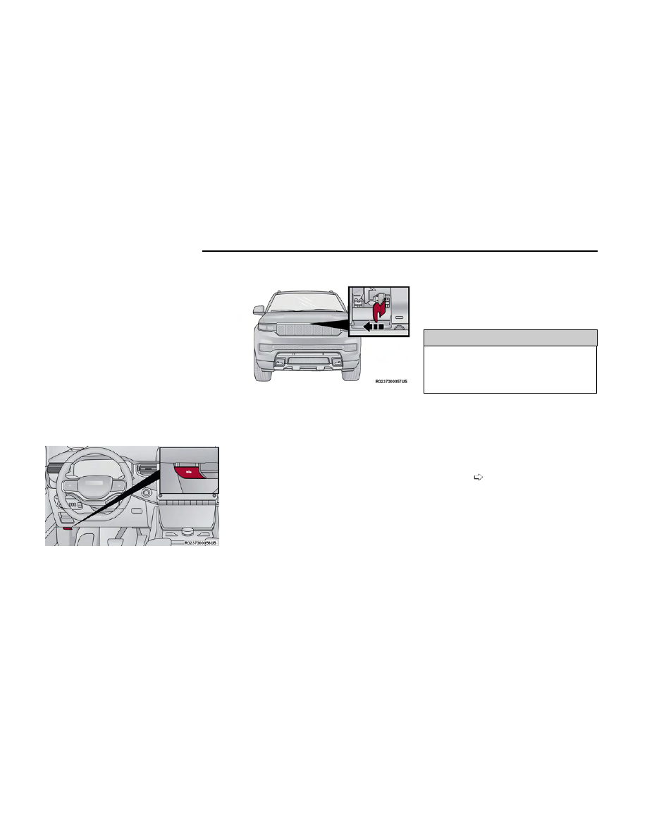
HOOD

OPENING THE HOOD

To open the hood, two latches must be released.

1. Pull the release lever located underneath the driv-

er’s side of the instrument panel.

2. Reach under the hood from outside the vehicle,

move the safety latch to the left and lift the hood.

NOTE:

Vehicle must be at a stop and the gear selector
must be in PARK.

While lifting the hood, use both hands.

Before lifting the hood, check that the wiper arms
are not in motion and not in the lifted position.

You may have to push down slightly on the hood
before pushing the safety latch.

CLOSING THE HOOD

In one continuous motion, pull down on the front edge
of the hood with moderate force until the angle is below
the crossover point (where the gas props are no longer
resisting) and let the hood continue to fall closed from
its own inertia.

WARNING!

Be sure the hood is fully latched before driving your
vehicle. If the hood is not fully latched, it could open
when the vehicle is in motion and block your vision.
Failure to follow this warning could result in serious
injury or death.

LIFTGATE

TO UNLOCK/OPEN THE LIFTGATE

The power liftgate may be opened by pushing the lift-
gate button on the key fob, pushing the liftgate button
in the cargo area, or by pushing the electronic liftgate
release handle

page 27.

Push the liftgate button on the key fob twice within five
seconds to open the power liftgate. Once the liftgate is
open, pushing the button twice within five seconds a
second time will close the liftgate.

Hood Release

Safety Latch Location

82

GETTING TO KNOW YOUR VEHICLE

NOTE:

If all doors are programmed to unlock on first press
within Uconnect Settings

page 182, all doors will

unlock when you push the electronic liftgate release. If
only the driver’s door is programmed, only the liftgate
will unlock when you push the electronic liftgate
release.

NOTE:

Use the power door lock switch on either front door
trim panel or the key fob to lock and unlock the
liftgate.

The driver's door lock cylinder will not lock and
unlock the liftgate.

The vehicle must be in PARK to utilize the liftgate
open/close button.

WARNING!

Driving with the liftgate open can allow poisonous
exhaust gases into your vehicle. You and your passen-
gers could be injured by these fumes. Keep the lift-
gate closed when you are operating the vehicle.

NOTE:

The liftgate can also be opened manually by pushing
the electronic liftgate release handle and pulling
upward in one fluid motion.

TO LOCK/CLOSE THE LIFTGATE

There are several different ways to close the liftgate:

Manually (grab the liftgate closing handle and pull
downward)

Key fob

Hands-free (if equipped)

Liftgate close button in the cargo area

With a valid Passive Entry key fob within 5 ft (1.5 m) of
the liftgate, pushing the Passive Entry button, located
to the left of the electronic liftgate release handle, will
lock the vehicle only.

If the liftgate is fully open, the liftgate can be closed by
pushing the liftgate close button located in the cargo
area on the left rear trim panel, near the liftgate open-
ing. If the liftgate is in motion, pushing the liftgate close
button a second time will reverse the liftgate operation.

ADJUSTABLE POWER LIFTGATE
HEIGHT

Use this QR code to access your digital
experience.

The maximum height that the liftgate
will open can be adjusted and saved so
that the liftgate will only open to the
desired height. To set a desired height,
proceed as follows:

1. Open the liftgate fully, then manually pull down on

the liftgate to the desired height.

2. Push and hold the liftgate close button, located on

the left side trim panel inside the cargo area, for
three seconds. An audible chime will be heard to let
you know the height has been saved.

Liftgate Entry

1 — Passive Entry Lock Button
2 — Electronic Liftgate Release Handle

Liftgate Close Button

Scan me

GETTING TO KNOW YOUR VEHICLE

83

2

To reset the saved height setting to a new setting, pro-
ceed as follows:

1. Open the liftgate, then manually push the liftgate

upward to its full open position.

2. Manually pull the liftgate down to the new desired

height and hold the liftgate close button for three
seconds until the audible chime is heard.

Power Liftgate Malfunction Procedure:

1. In the event of a power malfunction to the liftgate,

the liftgate can be released by accessing the service
release feature in the latch. This can be done using
a 3 mm diameter screwdriver.

2. From inside the gate, an eyelet can be seen. Place

the screwdriver in the eyelet.

3. Rotate the screwdriver handle to actuate the lever

and release the latch.

4. If liftgate is left open for an extended period of time,

the liftgate may need to be closed manually to reset
power liftgate functionality.

HANDS-FREE LIFTGATE

To open or close the liftgate using hands-free activa-
tion, use a straight in and out kicking motion under the
vehicle activation zone in the general location between
the park sensors. The activation zone is about 1 ft
(0.3 m) on each side from the centerline of the vehicle.
A sweeping motion under the activation zone can also
be used for hands-free activation to open or close the
liftgate.

NOTE:

The activation zone is the same for vehicles equipped
with or without a trailer tow package.

When a valid kicking motion is completed, the liftgate
will chime, the hazard lights will flash and the liftgate
will open after approximately one second, or close after
approximately three seconds. These settings can be
enabled or disabled through Uconnect Settings

page 182.

NOTE:

Opening or closing the Hands-Free Liftgate requires
a valid Passive Entry key fob within 5 ft (1.5 m) of
the liftgate handle. If a valid Passive Entry key fob is
not within 5 ft (1.5 m), the liftgate will not respond
to any kicks, and will perform inhibit chimes to
inform the user about the missing key fob.

The distance from the rear fascia/bumper to the
foot shall be no more than 8 inches (20 cm) to be
recognized as a valid kick.

The Hands-Free Liftgate feature may be turned on or
off through the Uconnect system

page 182.

The Hands-Free Liftgate feature should be turned
off during jacking, tire changing, manual car wash,
and vehicle service.

Liftgate Service Release

Hands-Free Liftgate Activation Zone

Valid Kicking Motion

84

GETTING TO KNOW YOUR VEHICLE

The Hands-Free Liftgate feature can be activated by
any metallic object making a similar in-and-out
motion under the rear fascia/bumper, such as
cleaning using a metal broom.

The Hands-Free Liftgate will only operate when the
transmission is in PARK.

If anything obstructs the Hands-Free Liftgate while it
is opening or closing, the liftgate will automatically
reverse to the closed/open position, provided it
meets sufficient resistance.

The Hands-Free Liftgate will not open with the key
fob in the cupholder or anywhere inside the vehicle.

There are pinch sensors attached to the side of the
liftgate opening. Light pressure anywhere along
these strips will cause the liftgate to return to the
open position.

If the power liftgate encounters multiple obstruc-
tions within the same cycle, the system will auto-
matically stop. If this occurs, the liftgate must be
operated manually.

The power liftgate will release, but not power open,
in temperatures below −12°F (−24°C). Be sure to
remove any buildup of snow or ice from the liftgate
before opening the liftgate.

If the liftgate is left open for an extended period of
time (approximately one hour), the liftgate may need
to be closed manually to reset power liftgate
functionality.

WARNING!

Driving with the liftgate open can allow poisonous
exhaust gases into your vehicle. You and your pas-
sengers could be injured by these fumes. Keep the
liftgate closed when you are operating the vehicle.

(Continued)

WARNING!

If you are required to drive with the liftgate open,
make sure that all windows are closed, and the
climate control blower switch is set at high speed.
Do not use the recirculation mode.

NOTE:

Allow the power system to open the liftgate. Manually
pushing or pulling the liftgate may activate the liftgate
obstacle detection feature and stop the power opera-
tion or reverse its direction.

WARNING!

During power operation, personal injury or cargo
damage may occur. Ensure the liftgate travel path is
clear. Make sure the liftgate is closed and latched
before driving away.

CARGO AREA FEATURES

Cargo Storage

The load floor is designed for a maximum load of
300 lb (136 kg), and should be uniformly distributed
over the load floor.

Additional storage can be found under the storage lid.
To access the lower storage, lift the handle and raise
the storage lid.

Cargo Tie-Down Hooks

The cargo tie-downs, located on the cargo area sides,
should be used to safely secure loads when the vehicle
is moving. The cargo tie downs are designed for a maxi-
mum load of 300 lb (136 kg) per tie-down.

Lift Load Floor Handle

Tie-Down Hooks

GETTING TO KNOW YOUR VEHICLE

85

2

WARNING!

Cargo tie-downs are not safe anchors for a child
seat tether strap. In a sudden stop or accident, a
tie-down could pull loose and allow the child seat
to come loose. A child could be badly injured. Use
only the anchors provided for child seat tethers.

To help protect against personal injury, passengers
should not be seated in the rear cargo area. The
rear cargo space is intended for load carrying pur-
poses only, not for passengers, who should sit in
seats and use seat belts.

The weight and position of cargo and passengers can
change the vehicle center of gravity and vehicle han-
dling. To avoid loss of control resulting in personal
injury, follow these guidelines for loading your vehicle:

Do not carry loads that exceed the load limits
described on the label attached to the left door or
left door center pillar.

Always place cargo evenly on the cargo floor. Put
heavier objects as low and as far forward as
possible.

Place as much cargo as possible in front of the
rear axle. Too much weight or improperly placed
weight over or behind the rear axle can cause the
vehicle to sway.

Do not pile luggage or cargo higher than the top of
the seatback. This could impair visibility or become
a dangerous projectile in a sudden stop or
accident.

Foldable Cargo Area Cover — If Equipped

The purpose of this cover is for privacy, not to secure
loads. It will not prevent cargo from shifting or protect
passengers from loose cargo.

To cover the cargo area:

1. Remove the folded cover from the storage pouch,

and unfold using a twisting motion.

2. Insert the pins on the ends of the cover into the

slots on each side of the pillar trim.

3. Hook the straps to the inside post of the rear head

restraint on each side.

NOTE:

The liftgate may be opened with the cargo cover in
place.

Foldable Cargo Area Cover

Step 2

Step 3

86

GETTING TO KNOW YOUR VEHICLE

To store the foldable cargo area cover, reverse the
installation steps and replace the cover into its storage
pouch.

WARNING!

In a collision, a loose cargo cover in the vehicle could
cause injury. It could fly around in a sudden stop and
strike someone in the vehicle. Do not store the cargo
cover on the cargo floor or in the passenger compart-
ment. Remove the cover from the vehicle when taken
from its mounting. Do not store it in the vehicle.

Retractable Cargo Area Cover —

If Equipped

The purpose of this cover is for privacy, not to secure
loads. It will not prevent cargo from shifting or protect
passengers from loose cargo.

To cover the cargo area:

1. Grab the cover at the center handle and pull over

the cargo area.

2. Insert the pins on the ends of the cover into the

slots in the pillar trim cover.

3. The liftgate may be opened with the cargo cover in

place.

WARNING!

In a collision, a loose cargo cover in the vehicle could
cause injury. It could fly around in a sudden stop and
strike someone in the vehicle. Do not store the cargo

(Continued)

WARNING!

cover on the cargo floor or in the passenger compart-
ment. Remove the cover from the vehicle when taken
from its mounting. Do not store it in the vehicle.

Cargo Net — If Equipped

The rear cargo area may be equipped with a cargo net
to keep items secure while driving.

To attach the cargo net, the clips must be hooked
through the loops on both sides of the cargo area.

ROOF LUGGAGE RACK — IF EQUIPPED

The crossbars and side rails are designed to carry
weight on vehicles equipped with a luggage rack.

The

load must not exceed 150 lb (68 kg), and should be
uniformly distributed over the luggage rack crossbars.

The crossbars on your vehicle are delivered stowed in
the rear cargo bin. Crossbars should always be used
whenever cargo is placed on the roof rack. Check the
straps frequently to be sure that the load remains
securely attached.

The roof rack does not increase the total load carrying
capacity of the vehicle. Be sure the total load of cargo
inside the vehicle plus that on the external rack does
not exceed the maximum vehicle load capacity.

Folding The Cargo Cover

1 — Remove Cover From Vehicle
2 — Twist Cover
3 — Push Twisted Cover Inward
4 — Place Folded Cover In Pouch

Rear Cargo Cover

GETTING TO KNOW YOUR VEHICLE

87

2

INSTALLING THE CROSSBARS

WARNING!

In a collision, loose crossbars in the vehicle could
cause injury. They could fly around in a sudden stop
and strike someone in the vehicle. Do not store the
crossbars on the cargo floor or in the passenger com-
partment. Remove the crossbars from the vehicle
when taken from their mounting. Do not store them in
the vehicle.

There are two crossbars equipped with your vehicle.
They are located in the rear cargo bin, stored in foam
blocks.

There is also a packet of fastener screws and a Torx
wrench provided in the foam blocks. You can find the
packet of fastener screws in the left foam block and the
Torx wrench in the right foam block.

There are three positions that the crossbars can be
installed in. There are also tie-down loops next to each
crossbar location on both sides of the roof.

NOTE:

The crossbars should only be used in positions 1 and
2 or positions 1 and 3. They are not designed to be
used in positions 2 and 3.

NOTE:

There are arrows on top of the crossbars that indicate
the direction that they should be installed. The arrows
should point forward toward the front of the vehicle.

Stowed Crossbars

1 — Fastener Screws
2 — Torx Wrench

Crossbar Locations

1 — Position 1
2 — Position 2
3 — Position 3

Crossbar and Tie Down Loop Locations

1 — Crossbar Installation Location
2 — Tie-Down Loop Locations

Crossbar Directional Arrow

88

GETTING TO KNOW YOUR VEHICLE

To install the crossbars, refer to the following
procedure:

1. Remove the crossbars from the foam blocks.

2. Swivel the outboard stanchion on the crossbar and

rotate it 180 degrees around the bolt to the open
position. Open the outboard stanchion on the oppo-
site end of the crossbar as well.

3. Using the provided Torx wrench, loosen the Torx

bolts on both ends of the crossbar.

4. Using the provided wrench and fasteners, bolt the

fasteners to the side rail.

NOTE:

An indicator on the wrench will show when the fas-
tener is tightened to the indicated torque specifica-
tion. The slanted line will line up with the arrow
when torquing.

5. Tighten down the Torx head bolts on the inboard

stanchion.

Step 2

Open Outboard Stanchion (Underside Shown)

Step 3

Torque Wrench Indicator

Step 4

Step 5

GETTING TO KNOW YOUR VEHICLE

89

2

NOTE:

It is important that the screws are left loose until
both sides of the crossbar are secured to the rail.

6. Repeat steps 2-5 for the second crossbar in the

desired position.

WARNING!

Cargo must be securely tied down before driving your
vehicle. Anything improperly secured to the roof rack,
crossbars, or the roof itself can fly off the vehicle,
particularly at high speeds, resulting in collisions,
personal injury or property damage. Follow the roof
rack cautions when carrying anything on your roof or
roof rack.

CAUTION!

To prevent damage to the roof of your vehicle, DO
NOT carry any loads on the roof rack without the
crossbars installed. The load should be secured
and placed on top of the crossbars, not directly on
the roof. If it is necessary to place the load on the
roof, place a blanket or other protective layer
between the load and the roof surface.

To avoid damage to the roof rack and vehicle, do
not exceed the maximum roof rack load capacity of
150 lb (68 kg). Always distribute heavy loads as
evenly as possible and appropriately secure the
load and any protective layer placed between the
load and the roof surface.

Load should always be secured to crossbars first,
with tie down loops used as additional securing
points if needed. Tie loops are intended as supple-
mentary tie down points only. Do not use ratchet-
ing mechanisms with the tie loops. Check the
straps and thumb wheels frequently to be sure
that the load remains securely attached.

Long loads that extend over the windshield, such
as wood panels or surfboards, or loads with large
frontal area should be secured to both the front
and rear of the vehicle.

Travel at reduced speeds and turn corners care-
fully when carrying large or heavy loads on the roof
rack. Wind forces, due to natural causes or nearby
truck traffic, can add sudden upward lift to a load.
This is especially true on large flat loads and may
result in damage to the cargo or your vehicle.

REMOVING THE CROSSBARS

To remove the crossbars, refer to the following
procedure:

1. Using the provided Torx wrench, loosen the Torx

head bolts on the stanchion. Do this on both ends of
the crossbar.

2. Using the provided wrench, remove the bolts that

secure the crossbar to the roof rail. Repeat this on
the other end of the crossbar.

Installed Crossbars

Step 1

Bolt Location

90

GETTING TO KNOW YOUR VEHICLE

3. Depress the swing key, and swivel the outboard

stanchion 180 degrees back to the stowed position.

4. Repeat steps 1-3 for the second crossbar.

5. Place the crossbars back into the foam blocks in the

rear cargo storage bin.

WARNING!

In a collision, loose crossbars in the vehicle could
cause injury. They could fly around in a sudden stop
and strike someone in the vehicle. Do not store the
crossbars on the cargo floor or in the passenger com-
partment. Remove the crossbars from the vehicle
when taken from their mounting. Do not store them in
the vehicle.

Depress The Swing Key

Step 3

GETTING TO KNOW YOUR VEHICLE

91

2

GETTING TO KNOW YOUR INSTRUMENT PANEL

BASE INSTRUMENT CLUSTER

92

Holding the

OK

button on the Instrument Cluster Dis-

play controls located on the steering wheel will allow
you to change your display from Digital to Analog.

Use this QR code to access your digital
experience.

INSTRUMENT CLUSTER
DESCRIPTIONS

1. Speedometer

Indicates vehicle speed.

2. Temperature Gauge

The temperature gauge shows engine coolant
temperature. Any reading within the normal
range indicates that the engine cooling system
is operating satisfactorily.

The pointer will likely indicate a higher tempera-
ture when driving in hot weather, up mountain
grades, or when towing a trailer. It should not be
allowed to exceed the upper limits of the normal
operating range.

WARNING!

A hot engine cooling system is dangerous. You or oth-
ers could be badly burned by steam or boiling cool-
ant. It is recommended to call an authorized dealer
for service if your vehicle overheats.

CAUTION!

Driving with a hot engine cooling system could dam-
age your vehicle. If the temperature gauge reads “H”
pull over and stop the vehicle. Idle the vehicle with
the air conditioner turned off until the pointer drops
back into the normal range. If the pointer remains on
the “H”, turn the engine off immediately and call an
authorized dealer for service.

3. Tachometer

Indicates the engine speed in revolutions per
minute (RPM x 1000).

4. Fuel Gauge

The pointer shows the level of fuel in the fuel
tank when the Keyless Push Button Ignition is in
the ON/RUN position.

The fuel pump symbol points to the
side of the vehicle where the fuel
door is located.

NOTE:

The Instrument Cluster Warning Indicators will illumi-
nate briefly for a bulb check when the ignition is first
cycled.

Scan me

GETTING TO KNOW YOUR INSTRUMENT PANEL

93

3

PREMIUM INSTRUMENT CLUSTER

94

GETTING TO KNOW YOUR INSTRUMENT PANEL

Holding the

OK

button on the Instrument Cluster Dis-

play controls located on the steering wheel will allow
you to change your display from Digital to Analog.

Use this QR code to access your digital
experience.

INSTRUMENT CLUSTER
DESCRIPTIONS

1. Speedometer

Indicates vehicle speed.

2. Temperature Gauge

The temperature gauge shows engine coolant
temperature. Any reading within the normal
range indicates that the engine cooling system
is operating satisfactorily.

The pointer will likely indicate a higher tempera-
ture when driving in hot weather, up mountain
grades, or when towing a trailer. It should not be
allowed to exceed the upper limits of the normal
operating range.

WARNING!

A hot engine cooling system is dangerous. You or oth-
ers could be badly burned by steam or boiling cool-
ant. It is recommended to call an authorized dealer
for service if your vehicle overheats

page 305.

CAUTION!

Driving with a hot engine cooling system could dam-
age your vehicle. If the temperature gauge reads “H”
pull over and stop the vehicle. Idle the vehicle with
the air conditioner turned off until the pointer drops
back into the normal range. If the pointer remains on
the “H”, turn the engine off immediately and call an
authorized dealer for service.

3. Tachometer

Indicates the engine speed in revolutions per
minute (RPM x 1000).

4. Fuel Gauge

The pointer shows the level of fuel in the fuel
tank when the Keyless Push Button Ignition is in
the ON/RUN position.

The fuel pump symbol points to the
side of the vehicle where the fuel
door is located.

NOTE:

The Instrument Cluster Warning Indicators will illumi-
nate briefly for a bulb check when the ignition is first
cycled.

INSTRUMENT CLUSTER DISPLAY

Depending on your vehicles trim level, features and
options may vary.

Your vehicle is equipped with an instrument cluster dis-
play, which offers useful information to the driver. With
the ignition in the OFF mode, opening/closing of a door

will activate the display for viewing, and display the total
miles, or kilometers, in the odometer. Your instrument
cluster display is designed to display important informa-
tion about your vehicle’s systems and features. Using a
driver interactive display located on the instrument
panel, your instrument cluster display can show how
systems are working and give you warnings when they
are not. The steering wheel mounted controls allow you
to scroll through the main menus and submenus. You
can access the specific information you want and make
selections and adjustments.

LOCATION AND CONTROLS

Scan me

Instrument Cluster Display/Controls Location

1 – Instrument Cluster Display Screen
2 – Instrument Cluster Display Controls

GETTING TO KNOW YOUR INSTRUMENT PANEL

95

3

The system allows the driver to select information by
pushing the following buttons mounted on the steering
wheel:

1.

Up

Arrow Button

Push and release the

up

arrow button to scroll

upward through the main menu.

2.

OK

Button

Push the

OK

button to access/select the informa-

tion screens or submenu screens of a main menu
item. Push and hold the

OK

button for one second

to reset displayed/selected features that can be
reset.

3.

MENU

Button

Push the

MENU

button to access/select the infor-

mation screens or submenu screens of the Home
Screen display. Push and hold the

OK

button to

enter edit mode.

4.

Left

Arrow Button

Push the

left

arrow button to return to the main

menu from an info screen or submenu item.

5.

Down

Arrow Button

Push and release the

down

arrow button to

scroll downward through the main menu.

6.

Right

Arrow Button

Push and release the

right

arrow button to

access the information screens or submenu screens
of a main menu item.

Display Options

Holding

OK

will also allow you to change your display to

Digital or Analog.

Digital theme will be the default theme

Menu screen times out after 10 seconds. Press

OK

to reactivate

Speedometer must always be present

Relevant warning notifications and other pop-up info
will still be displayed in the main screen area (In this
case the speed moves to the top)

Custom Tile Configuration

To customize the instrument cluster further, you are
able to select up to five tiles to display information
based on your needs.

Press the

MENU

button for the Home Screen display

Navigate

Left

or

Right

to highlight desired tile

Press

OK

to select the tile and navigate to the

selected submenu and press

OK

again to add your

selection to your tile view

The main menu options of the home screen are;
Driver Info, Vehicle Info, Navigation (if equipped),
Audio, and Off Road

Instrument Cluster Display Control Buttons

1 — Up Arrow Button
2 — OK Button
3 — Menu Button
4 — Left Arrow Button
5 — Down Arrow Button
6 — Right Arrow Button

Menu Button

Customizable Tile Layout

96

GETTING TO KNOW YOUR INSTRUMENT PANEL

You can customize your Instrument Cluster Display with
up to five tiles that may consist of the following:

NOTE:

These options may vary based on your vehicle trim
level.

Navigation

Map (Route Set / Route Not Set)

Trip A / Trip B

Vehicle Info

Coolant Temp

Trans Temp

Oil Temp

Oil Pressure

Battery Voltage

Oil Life

Tire Pressure

Fuel Economy

Driver Info – If Equipped

Posted Speed Limit Sign

Driver Assist

Audio

Audio Info

Off Road – If Equipped

Selec-Terrain / Air Suspension Status

Steering Angle

Pitch

Roll

Trailer Tow – If Equipped

Trailer Trip

Trailer Brake

Trailer Tire Pressure

ENGINE OIL LIFE RESET

Use this QR code to access your digital
experience.

Oil Level

The 3.0L engine does not have a tradi-
tional “dipstick” and there is no need to
manually check the oil level

page 295.

Oil Change Required

Your vehicle is equipped with an engine oil change indi-
cator system. The “Oil Change Required” message will
display in the instrument cluster display for five sec-
onds after a single chime has sounded, to indicate the
next scheduled oil change interval. The engine oil
change indicator system is duty cycle based, which
means the engine oil change interval may fluctuate,
dependent upon your personal driving style and envi-
ronmental conditions.

Unless reset, this message will continue to display each
time the ignition is placed in the ON/RUN position. To
turn off the message temporarily, push and release the

OK

or arrow buttons. To reset the oil change indicator

system (after performing the scheduled maintenance),
refer to the following procedure.

Vehicles Equipped With Keyless Enter ‘n Go™ Ignition

Use the steering wheel instrument cluster display con-
trols for the following procedure(s):

1. Without pressing the brake pedal, push the ENGINE

START/STOP button and place the ignition in the
ON/RUN position (do not start the engine).

2. Push and release the

down

arrow button to

scroll downward through the main menu to “Vehicle
Info”.

3. Push and release the

right

arrow button to

access the “Oil Life” screen.

4. Push and hold the

OK

button to reset oil life. If con-

ditions are met, the gauge and numeric display will
update to show 100%. If conditions are not met a
pop-up message of “To reset oil life engine must be
off with ignition in run” will be displayed (for five
seconds), and the user will remain at the Oil Life
screen.

5. Push and release the

up

or

down

arrow

button to exit the submenu screen.

NOTE:

If the indicator message illuminates when you start the
vehicle, the oil change indicator system did not reset. If
necessary, repeat this procedure.

Secondary Method Of Resetting Engine Oil Life

1. Without pressing the brake pedal, push the ENGINE

START/STOP button and place the ignition to the
ON/RUN position (do not start the engine).

2. Fully press the accelerator pedal, slowly, three times

within 10 seconds.

3. Without pushing the brake pedal, push the ENGINE

START/STOP button once to return the ignition to the
OFF position.

NOTE:

If the indicator message illuminates when you start the
vehicle, the oil change indicator system did not reset. If
necessary, repeat this procedure.

Scan me

GETTING TO KNOW YOUR INSTRUMENT PANEL

97

3

DISPLAY AND MESSAGES

The instrument cluster display is located in the center
portion of the cluster and consist of multiple sections:

Main Screen — The inner ring of the display will illu-
minate in black under normal conditions, yellow for
noncritical warnings and red for critical warnings

Submenu Dots — Whenever there are submenus
available, the position within the submenus is
shown here

Reconfigurable Telltales/Information

Gear Selector Status (PRND)

Driver Interactive Display (Compass, Temp, Range to
Empty, Trip A, Trip B, Average Fuel Economy, Current
Fuel Economy and Time)

Air Suspension Status — If Equipped

Four-Wheel Drive (4WD) Status — If Equipped

The instrument cluster display will normally display the
main menu or the screens of a selected feature of the

main menu. The main display area also displays pop-up
messages and warning or information messages. These
pop-up messages fall into several categories:

Five Second Stored Messages

When the appropriate conditions occur, this type of
message takes control of the main display area for
five seconds and then returns to the previous
screen. Most of the messages of this type are then
stored (as long as the condition that activated it
remains active) and can be reviewed from the “Mes-
sages” main menu item. Examples of this message
type are “Right Front Turn Signal Lamp Out” and
“Low Tire Pressure”.

Unstored Messages

This message type is displayed indefinitely or until
the condition that activated the message is cleared.
Examples of this message type are “Turn Signal On”
(if a turn signal is left on) and “Lights On” (if driver
leaves the vehicle with the lights on).

Unstored Messages Until RUN

These messages deal primarily with the Remote
Start feature. This message type is displayed until
the ignition is in the RUN state. Examples of this
message type are “Remote Start Canceled - Door
Ajar” and “Press Brake Pedal and Push Button to
Start”.

Five Second Unstored Messages

When the appropriate conditions occur, this type of
message takes control of the main display area for
five seconds and then returns to the previous
screen. An example of this message type is “Auto-
matic High Beams On”.

Messages include the following, but not limited to:

NOTE:

Certain messages may require dealer service.

Front Seat Belts Unbuckled

Oil Change Due

ACC Override

Driver Seat Belt Unbuckled

Fuel Low

Cruise Set To XXX mph or km/h

Passenger Seat Belt Unbuckled

Service Anti-lock Brake System

Service Shifter

Traction Control Off

Service Electronic Throttle Control

Tire Pressure Screen With Low Tire(s)

Washer Fluid Low

Service Power Steering

Service Tire Pressure System

Oil Pressure Low

Cruise Off

Park Brake Engaged

Oil Level Low – If Equipped

Cruise Ready

Brake Fluid Low

Engine Temperature Hot

Lights On

Right Front Turn Signal Light Out

Right Rear Turn Signal Light Out

Left Front Turn Signal Light Out

Left Rear Turn Signal Light Out

Ignition or Accessory On

Vehicle Not In Park

Remote Start Active Push Start Button

Remote Start Canceled Fuel Low

Remote Start Canceled Hood Open

Remote Start Canceled Liftgate Open

98

GETTING TO KNOW YOUR INSTRUMENT PANEL

Remote Start Canceled Door Open

Remote Start Canceled Time Expired

Remote Start Disabled Start To Reset

Service Air Bag System

Service Air Bag Warning Light

Door Open

Doors Open

Hood Open

Vehicle Speed Too High To Shift to D

Liftgate Open

Shift Not Allowed

Vehicle Speed is Too High to Shift to R

Vehicle Speed is Too High to Shift to P

Service Transmission

INSTRUMENT CLUSTER DISPLAY
MENU ITEMS

The instrument cluster display can be used to view the
main menu items for several features. Use the

up

and

down

arrow buttons to scroll through the

driver interactive display menu options until the desired
menu is reached.

NOTE:

Depending on the vehicle’s options, feature settings
may vary.

Main Menu

SPEEDOMETER

Push and release the

up

or

down

arrow button

until the Speedometer icon/title is highlighted in the
instrument cluster display.

Push and release the

OK

button to toggle units (mph

or km/h) of the speedometer. Hold the

OK

button to

toggle between Analog and Digital speedometer.

DRIVER INFO

Push and release the

up

or

down

arrow button

until the Driver Info icon/title is highlighted in the instru-
ment cluster display. Push the

left

or

right

arrow button to scroll through the information
submenus.

Driver Assist — If Equipped

The Driver Assist screen indicates the current status of
ACC, Active Lane Management and Active Driving
Assist/Assist+/Pilot

page 151.

Night Vision — If Equipped

Arrow buttons and submenu indicators dis-
appear after five seconds of menu naviga-
tion inactivity. Pedestrian/Animal icons will
be displayed in the top left location

page 161.

VEHICLE INFO

Push and release the

up

or

down

arrow button

until the Vehicle Info icon/title is highlighted in the
instrument cluster display. Push the

left

or

right

arrow button to scroll through the information

submenus.

Fuel Economy

Average Fuel Economy

Current Fuel Economy

Range To Empty

Press the

OK

button to reset the average fuel

economy

NOTE:

The Range feature is not able to be reset through the
instrument cluster display controls.

Gauge Summary

Coolant Temperature — If Equipped

Displays the current temperature of the coolant.

Battery Voltage

Displays the current voltage level of the battery.

Transmission Temperature

Displays the actual transmission temperature.

Oil Temperature

Displays the actual oil temperature.

Oil Pressure

Displays the actual oil pressure.

Oil Life

Displays the current oil life of the vehicle.

Oil Level — If Equipped

Displays the current oil level of the vehicle

page 295.

GETTING TO KNOW YOUR INSTRUMENT PANEL

99

3

Tire Pressure Monitoring System

If tire pressure is

OK

for all tires a vehicle icon is

displayed with tire pressure values in each corner of
the icon.

If one or more tires have low pressure, “Inflate Tire
To XX” is displayed with the vehicle icon and the tire
pressure values in each corner of the icon with the
pressure value of the low tire are displayed in a dif-
ferent color than the other tire pressure value.

If the Tire Pressure system requires service, “Ser-
vice Tire Pressure System” is displayed.

Tire Pressure is an information only function, and can-
not be reset

page 240.

Stop/Start Status — If Equipped

Display current status of Stop/Start system.

TRIP

Push and release the

up

or

down

arrow button

until the Trip menu title is displayed in the instrument
cluster display. Toggle the

left

or

right

arrow but-

ton to select Trip A or Trip B. The Trip information will
display the following:

Distance

– Shows the total distance (mi or km) trav-

eled for Trip A or Trip B since the last reset.

Average Fuel Economy

– Shows the average fuel

economy (mpg or L/100 km or km/L) of Trip A or
Trip B since the last reset.

Elapsed Time

– Shows the total elapsed time of

travel since Trip A or Trip B has been reset.

Hold the

OK

button to reset feature information.

NAVIGATION — IF EQUIPPED

Push and release the

left

or

right

arrow button

until the Navigation display icon/title is highlighted in
the instrument cluster display.

“Hold

OK

to Start Route” will display when no active

route is set.

“Hold

OK

to Cancel Route” will display when an

active route is set.

OFF ROAD

Push and release the

up

or

down

arrow button

until the Off Road Menu icon/title is highlighted. Push
the

left

or

right

arrow button to scroll the

submenus.

Terrain Status

Selec-Terrain Status

Air Suspension Status — If Equipped

Vehicle Dynamics

Wheel Articulation

Transfer Case Status

Steering Angle

Pitch And Roll

Vehicle Pitch

Vehicle Roll

TRAILER TOW — IF EQUIPPED

Push and release the

up

or

down

arrow button

until the Trailer Tow Menu icon/title is highlighted in the
instrument cluster display. Push and release the

left

or

right

arrow button to select Trailer Trip or

Trailer Brake.

Trailer Trip

will display the following:

Distance

NOTE:

Press and hold the

OK

button to reset all the information.

Trailer Brake

will display the following:

Output

Type

Gain

Trailer Tire Pressure

will display the following:

Trailer Tire Pressure

Trailer Light Status

will display the following:

Running Light Status

Left Brake Light Status

Right Brake Light Status

Left Turn Signal Status

Right Turn Signal Status

Reverse Lights Status

AUDIO

Push and release the

up

or

down

arrow button

until the Audio Menu icon/title is highlighted in the
instrument cluster display. This menu will display the
audio source information, including the Song name,
Artist name, and audio source with an accompanying
graphic.

MESSAGES

Push and release the

up

or

down

arrow button

until the Messages Menu item is highlighted. This fea-
ture shows the number of stored warning messages.
Pushing the

left

or

right

arrow button will allow

you to see what the stored messages are.

When no messages are present, main menu icon will
be a closed envelope.

100

GETTING TO KNOW YOUR INSTRUMENT PANEL

SETTINGS

NOTE:

If current theme is set to Digital, tachometer will not
display while in the Settings menu.

NOTE:

If your vehicle is equipped with Head Up Display (HUD),
feature settings are available at any vehicle speed

page 101.

Screen Setup

Push and release the

up

or

down

arrow button

until the Settings Menu icon/title is highlighted in the
instrument cluster display. Push and release the

OK

button to enter the submenus and follow the prompts
on the screen as needed. The Settings feature allows
you to change what information is displayed in the
instrument cluster as well as the location that informa-
tion is displayed.

Upper Left or Upper Right

None

Fuel Economy
Average

Compass

Outside Temp

Trip A Distance

Time

Range To Empty
(RTE)

Trip B Distance

Fuel Economy
Current

Trailer Trip

Current Gear

On

Off

Odometer

Show

Hide

Fuel Gauge

Show Range

Hide Range

Favorite Menus

Trip
(Show/Hide)

Navigation
(Show/Hide)

Audio
(Show/Hide)

Off Road
(Show/Hide)

Trailer Tow
(Show/Hide)

NOTE:

Menus with (show/hide) can push the

OK

button to

choose whether to show or hide this menu on the
instrument cluster display.

Defaults (Restores All Settings To Default Settings)

Restore

Cancel

HEAD UP DISPLAY (HUD) —
IF EQUIPPED

Use this QR code to access your digital
experience.

NOTE:

The HUD feature Settings are available
at any vehicle speed. Some information
like speed limit or Driver Assist will not appear on the
HUD unless your vehicle is equipped Traffic Sign Assist
or Driver Assist systems.

Push and release the

up

or

down

arrow button

until the Settings Menu icon/title is highlighted in the
instrument cluster display. Push and release the

left

right

arrow button until the HUD Menu icon/

title is highlighted in the instrument cluster display.
Push and release the

OK

button to enter HUD. Use the

up

or

down

arrow button to select a setting,

then push and release the

OK

button to adjust the

setting.

ON/OFF

When “Display On” is selected, the HUD will display
on the windshield. When it is not selected, nothing
will display on the windshield.

Content and Layout

Simple

: Speed, Speed Limit

Standard

: Speed, Speed Limit, Navigation

Scan me

HUD ON/OFF

GETTING TO KNOW YOUR INSTRUMENT PANEL

101

3

When “Standard” mode is selected, the HUD
image is split into thirds with the speed limit
indicator shown to the left, vehicle speed in the
center, and turn-by-turn navigation to the right.

Advanced

: Speed, Speed Limit, Navigation, Driver

Assist (ACC/Cruise, Active Lane Management,
Active Driving Assist), Gear (only available in
Sport mode)

When “Advanced” mode is selected, the HUD
displays the vehicle speed, turn-by-turn naviga-
tion, speed limit, driver assist function(s), and
current gear.

Custom 1

: Speed, Speed Limit

Custom 2

: Speed, Speed Limit, Navigation

Custom 3

: Speed, Speed Limit, Navigation, Driver

Assist (ACC/Cruise, Active Lane Management,
Active Driving Assist)

Custom 4

: Speed, Speed Limit, Navigation, Driver

Assist (ACC/Cruise, Active Lane Management,
Active Driving Assist), Gear (only available in
Sport mode)

Display Height

Brightness

NOTE:

The HUD basic settings (Brightness, Display Height
and Non Custom layouts), are controlled through the
Settings Screen in the Instrument Cluster

page 95.

If current theme is set to Digital, tachometer will not
display while in the Settings menu.

BATTERY SAVER ON/BATTERY
SAVER MODE MESSAGE —
ELECTRICAL LOAD REDUCTION
ACTIONS (IF EQUIPPED)

This vehicle is equipped with an Intelligent Battery Sen-
sor (IBS) to perform additional monitoring of the electri-
cal system and status of the vehicle battery.

In cases when the IBS detects charging system failure,
or the vehicle battery conditions are deteriorating, elec-
trical load reduction actions will take place to extend

the driving time and distance of the vehicle. This is
done by reducing power to or turning off non-essential
electrical loads.

Load reduction is only active when the engine is run-
ning. It will display a message if there is a risk of battery
depletion to the point where the vehicle may stall due
to lack of electrical supply, or will not restart after the
current drive cycle.

When load reduction is activated, the message “Battery
Saver On” or “Battery Saver Mode” will appear in the
instrument cluster.

These messages indicate the vehicle battery has a low
state of charge and continues to lose electrical charge
at a rate that the charging system cannot sustain.

NOTE:

The charging system is independent from load
reduction. The charging system performs a diagnos-
tic on the charging system continuously.

If the Battery Charge Warning Light is on it may indi-
cate a problem with the charging system

page 104.

The following are electrical loads that may be switched
off (if equipped), and vehicle functions which can be
affected by load reduction:

Heated Seat/Vented Seats/Heated Wheel

Rear Defroster And Heated Mirrors

HVAC System

115 Volt AC Power Inverter System

Audio and Telematics System

Standard Mode

Advanced Mode

102

GETTING TO KNOW YOUR INSTRUMENT PANEL

Loss of the battery charge may indicate one or more of
the following conditions:

The charging system cannot deliver enough electri-
cal power to the vehicle system because the electri-
cal loads are larger than the capability of the charg-
ing system. The charging system is still functioning
properly.

Turning on all possible vehicle electrical loads (e.g.
HVAC to max settings, exterior and interior lights,
overloaded power outlets +12 Volt, 115 Volt AC, USB
ports) during certain driving conditions (city driving,
towing, frequent stopping, etc.).

Installing options like additional lights, upfitter elec-
trical accessories, audio systems, alarms and simi-
lar devices.

Unusual driving cycles (short trips separated by long
parking periods).

The vehicle was parked for an extended period of
time (weeks, months).

The battery was recently replaced and was not
charged completely.

The battery was discharged by an electrical load left
on when the vehicle was parked.

The battery was used for an extended period with
the engine not running to supply radio, lights, char-
gers, +12 Volt portable appliances like vacuum
cleaners, game consoles and similar devices.

What to do when an electrical load reduction action
message is present (“Battery Saver On” or “Battery
Saver Mode”)

During a trip:

Reduce power to unnecessary loads if possible:

Turn off redundant lights (interior or exterior)

Check what may be plugged in to power outlets
+12 Volt, 115 Volt AC, USB ports

Check HVAC settings (blower, temperature)

Check the audio settings (volume)

After a trip:

Check if any aftermarket equipment was installed
(additional lights, upfitter electrical accessories,
audio systems, alarms) and review specifications if
any (load and Ignition Off Draw currents).

Evaluate the latest driving cycles (distance, driving
time and parking time).

The vehicle should have service performed if the
message is still present during consecutive trips,
and if the evaluation and driving pattern of the
vehicle did not help to identify the cause.

WARNING LIGHTS AND MESSAGES

The warning/indicator lights will illuminate in the instru-
ment panel together with a dedicated message and/or
acoustic signal when applicable. These indications are
indicative and precautionary and as such must not be
considered as exhaustive and/or alternative to the
information contained in the Owner’s Manual, which
you are advised to read carefully in all cases. Always
refer to the information in this chapter in the event of a
failure indication. All active telltales will display first if
applicable. The system check menu may appear differ-
ent based upon equipment options and current vehicle
status. Some telltales are optional and may not appear.

RED WARNING LIGHTS

Air Bag Warning Light

This warning light will illuminate to indicate a
fault with the air bag, and will turn on for
four to eight seconds as a bulb check when
the ignition is placed in the ON/RUN posi-

tion. This light will illuminate with a single chime when a
fault with the air bag has been detected, it will stay on
until the fault is cleared. If the light is either not on dur-
ing startup, stays on, or turns on while driving, have the
system inspected at an authorized dealer as soon as
possible.

Brake Warning Light

This warning light monitors various brake
functions, including brake fluid level and
parking brake application. If the brake light
turns on it may indicate that the parking

brake is applied, that the brake fluid level is low, or that
there is a problem with the Anti-Lock Brake System
reservoir.

If the light remains on when the parking brake has
been disengaged, and the fluid level is at the full mark
on the master cylinder reservoir, it indicates a possible
brake hydraulic system malfunction or that a problem
with the Brake Booster has been detected by the Anti-
Lock Brake System (ABS) / Electronic Stability Control
(ESC) system. In this case, the light will remain on until
the condition has been corrected. If the problem is
related to the brake booster, the ABS pump will run
when applying the brake, and a brake pedal pulsation
may be felt during each stop.

The dual brake system provides a reserve braking
capacity in the event of a failure to a portion of the
hydraulic system. A leak in either half of the dual brake

GETTING TO KNOW YOUR INSTRUMENT PANEL

103

3

system is indicated by the Brake Warning Light, which
will turn on when the brake fluid level in the master
cylinder has dropped below a specified level.

The light will remain on until the cause is corrected.

NOTE:

The light may flash momentarily during sharp cornering
maneuvers, which change fluid level conditions. The
vehicle should have service performed, and the brake
fluid level checked.

If brake failure is indicated, immediate repair is
necessary.

WARNING!

Driving a vehicle with the red brake light on is danger-
ous. Part of the brake system may have failed. It will
take longer to stop the vehicle. You could have a colli-
sion. Have the vehicle checked immediately.

Vehicles equipped with the Anti-Lock Brake System
(ABS) are also equipped with Electronic Brake Force
Distribution (EBD). In the event of an EBD failure, the
Brake Warning Light will turn on along with the ABS
Light. Immediate repair to the ABS system is required.

Operation of the Brake Warning Light can be checked by
turning the ignition switch from the OFF position to the
ON/RUN position. The light should illuminate for approxi-
mately two seconds. The light should then turn off unless
the parking brake is applied or a brake fault is detected. If
the light does not illuminate, have the light inspected by
an authorized dealer.

The light also will turn on when the parking brake is
applied with the ignition switch in the ON/RUN position.

NOTE:

This light shows only that the parking brake is applied.
It does not show the degree of brake application.

Battery Charge Warning Light

This warning light will illuminate when the
battery is not charging properly. If it stays on
while the engine is running, there may be a
malfunction with the charging system. Con-

tact an authorized dealer as soon as possible.
This indicates a possible problem with the electrical
system or a related component.

Door Open Warning Light

This indicator will illuminate when a door is
ajar/open and not fully closed.

NOTE:

If the vehicle is moving, there will also be a single
chime.

Drowsy Driver Detected Warning Light —

If Equipped

The Drowsy Driver Detected (DDD) system,
monitors certain vehicle movement and
driver interactions to identify patterns sug-
gesting drowsiness. If detected, the system

sends the driver an auditory and visual signal to take
precaution. A pop-up will display continuously until the
driver presses the

OK

button to clear.

Once the pop-up message is cleared, it is stored until
the condition is no longer true

page 228.

Electric Power Steering (EPS) Fault

Warning Light

This warning light will turn on when there's a
fault with the EPS system

page 127.

WARNING!

Continued operation with reduced assist could pose a
safety risk to yourself and others. Service should be
obtained as soon as possible.

Electronic Throttle Control (ETC) Warning

Light

This warning light will illuminate to indicate a
problem with the ETC system. If a problem is
detected while the vehicle is running, the
light will either stay on or flash depending on

the nature of the problem. Cycle the ignition when the
vehicle is safely and completely stopped and the trans-
mission is placed in the PARK position. The light should
turn off. If the light remains on with the vehicle running,
your vehicle will usually be drivable; however, see an
authorized dealer for service as soon as possible.

NOTE:

This light may turn on if the accelerator and brake ped-
als are pressed at the same time.

If the light continues to flash when the vehicle is run-
ning, immediate service is required and you may experi-
ence reduced performance, an elevated/rough idle, or
engine stall and your vehicle may require towing. The
light will come on when the ignition is placed in the

104

GETTING TO KNOW YOUR INSTRUMENT PANEL

ON/RUN position and remain on briefly as a bulb
check. If the light does not come on during starting,
have the system checked by an authorized dealer.

Engine Coolant Temperature Warning

Light

This warning light warns of an overheated
engine condition. If the engine coolant tem-
perature is too high, this indicator will illumi-
nate and a single chime will sound. If the tem-

perature reaches the upper limit, a continuous chime will
sound for four minutes or until the engine is able to cool;
whichever comes first.

If the light turns on while driving, safely pull over and stop
the vehicle. If the Air Conditioning (A/C) system is on, turn
it off. Also, shift the transmission into NEUTRAL (N) and
idle the vehicle. If the temperature reading does not
return to normal, turn the engine off immediately and call
for service

page 284.

Hood Open Warning Light

This warning light will illuminate when the
hood is left open and not fully closed.

NOTE:

If the vehicle is moving, there will also be a single
chime.

Liftgate Open Warning Light

This warning light will illuminate when the
liftgate is open.

NOTE:

If the vehicle is moving, there will also be a single
chime.

Night Vision Animal Detected Warning

Light — If Equipped

The Night Vision Animal Warning Light will
illuminate in red when an animal is detected
directly in the vehicle’s path, near the head-
lights, and a collision is possible.

If enabled, a chime will sound and a video pop-up may
display when a detection occurs.

Night Vision Pedestrian Detected

Warning Light — If Equipped

The Night Vision Pedestrian Warning Light
will illuminate in red when a pedestrian is
detected directly in the vehicle’s path, near
the headlights, and a collision is possible.

If enabled, a chime will sound and a video pop-up may
display when a detection occurs.

Oil Pressure Warning Light

This warning light will illuminate to indicate
low engine oil pressure. If the light turns on
while driving, stop the vehicle, shut off the
engine as soon as possible, and contact an

authorized dealer. A chime will sound when this light
turns on.

Do not operate the vehicle until the cause is corrected.
This light does not indicate how much oil is in the
engine.

Oil Temperature Warning Light

This warning light will illuminate to indicate
the engine oil temperature is high. If the light
turns on while driving, safely pull over and
stop the vehicle (keep engine running). If the

temperature does not return to normal after a few min-
utes, turn off the engine and call for service.

Seat Belt Reminder Warning Light

This warning light indicates when the driver
or passenger seat belt is unbuckled. When
the ignition is first placed in the ON/RUN
position and if the driver’s seat belt is

unbuckled, a chime will sound and the light will turn on.
When driving, if the driver or front passenger seat belt
remains unbuckled, the Seat Belt Reminder Light will
flash or remain on continuously and a chime will sound

page 243.

Transmission Temperature Warning

Light — If Equipped

This warning light will illuminate to warn of a
high transmission fluid temperature. This
may occur with strenuous usage such as
trailer towing. If this light turns on, stop the

vehicle and run the engine at idle or slightly faster, with
the transmission in PARK (P) or NEUTRAL (N), until the
light turns off. Once the light turns off, you may con-
tinue to drive normally.

GETTING TO KNOW YOUR INSTRUMENT PANEL

105

3

WARNING!

If you continue operating the vehicle when the Trans-
mission Temperature Warning Light is illuminated you
could cause the fluid to boil over, come in contact
with hot engine or exhaust components and cause a
fire.

CAUTION!

Continuous driving with the Transmission Tempera-
ture Warning Light illuminated will eventually cause
severe transmission damage or transmission failure.

Vehicle Security Warning Light —

If Equipped

This light will flash at a fast rate for approxi-
mately 15 seconds when the vehicle security
system is arming, and then will flash slowly
until the vehicle is disarmed.

YELLOW WARNING LIGHTS

Anti-Lock Brake System (ABS) Warning

Light

This warning light monitors the ABS. The
light will turn on when the ignition is placed
in the ON/RUN position and may stay on for
as long as four seconds.

If the ABS light remains on or turns on while driving, then
the Anti-Lock portion of the brake system is not function-
ing and service is required as soon as possible. However,
the conventional brake system will continue to operate
normally, assuming the Brake Warning Light is not also
on.

If the ABS light does not turn on when the ignition is
placed in the ON/RUN position, have the brake system
inspected by an authorized dealer.

Air Suspension Fault Warning Light

This light will illuminate when there is a fault
detected in the air suspension system.

Drowsy Driver Detected System Fault

Warning Light — If Equipped

This warning light will illuminate when the
Drowsy Driver Detected (DDD) system is not
operating correctly and requires service.
Please see an authorized dealer.

Electric Park Brake Warning Light

This warning light will illuminate to indicate
the Electric Park Brake is not functioning
properly and service is required. Contact an
authorized dealer.

Electronic Stability Control (ESC) Active

Warning Light

This warning light will indicate when the ESC
system is Active. The ESC Indicator Light in
the instrument cluster will come on when the
ignition is placed in the ON/RUN position,

and when ESC is activated. It should go out with the
engine running. If the ESC Indicator Light comes on
continuously with the engine running, a malfunction
has been detected in the ESC system. If this warning
light remains on after several ignition cycles, and the
vehicle has been driven several miles (kilometers) at
speeds greater than 30 mph (48 km/h), see an autho-
rized dealer as soon as possible to have the problem
diagnosed and corrected.

The ESC OFF Indicator Light and the ESC Indicator
Light come on momentarily each time the ignition is
placed in the ON/RUN position.

The ESC system will make buzzing or clicking
sounds when it is active. This is normal; the sounds
will stop when ESC becomes inactive.

This light will come on when the vehicle is in an ESC
event.

Electronic Stability Control (ESC) OFF

Warning Light

This warning light indicates the ESC is off.

Each time the ignition is turned to ON/RUN,
the ESC system will be on, even if it was
turned off previously.

Service Active Lane Management

Warning Light — If Equipped

This warning light will illuminate when the
Active Lane Management system is not oper-
ating and requires service. Please see an
authorized dealer.

106

GETTING TO KNOW YOUR INSTRUMENT PANEL

Active Lane Management Warning

Light — If Equipped

The Active Lane Management Warning Light
will be solid yellow when the vehicle is
approaching a lane marker. The warning
light will flash when the vehicle is crossing

the lane marker

page 157.

Low Fuel Warning Light

When the fuel level reaches approximately
2 gal (7.5 L), this light will turn on and a
chime will sound. The light will remain on
until fuel is added.

Fuel Cutoff Failure Warning Light —

If Equipped

This light will illuminate if there is a fuel cut-
off failure. If this light illuminates, take it to
an authorized dealer and have them inspect
it.

Low Washer Fluid Warning Light

This warning light will illuminate when the
windshield washer fluid is low

page 296.

Engine Check/Malfunction Indicator

Warning Light (MIL)

The Engine Check/Malfunction Indicator
Light (MIL) is a part of an Onboard Diagnos-
tic System called OBD II that monitors
engine and automatic transmission control

systems. This warning light will illuminate when the igni-

tion is in the ON/RUN position before engine start. If
the bulb does not come on when turning the ignition
switch from OFF to ON/RUN, have the condition
checked promptly.

Certain conditions, such as a loose or missing gas cap,
poor quality fuel, etc., may illuminate the light after
engine start. The vehicle should be serviced if the light
stays on through several typical driving styles. In most
situations, the vehicle will drive normally and will not
require towing.

When the engine is running, the MIL may flash to alert
serious conditions that could lead to immediate loss of
power or severe catalytic converter damage. The
vehicle should be serviced by an authorized dealer as
soon as possible if this occurs.

WARNING!

A malfunctioning catalytic converter, as referenced
previously, can reach higher temperatures than in
normal operating conditions. This can cause a fire if
you drive slowly or park over flammable substances
such as dry plants, wood, cardboard, etc. This could
result in death or serious injury to the driver, occu-
pants or others.

CAUTION!

Prolonged driving with the Malfunction Indicator Light
(MIL) on could cause damage to the vehicle control
system. It also could affect fuel economy and drive-
ability. If the MIL is flashing, severe catalytic converter
damage and power loss will soon occur. Immediate
service is required.

Night Vision Animal Detected Warning

Light — If Equipped

This light alerts the driver that the Night
Vision Warning System has detected an ani-
mal approaching in the vehicle’s path.

Night Vision Pedestrian Detected

Warning Light — If Equipped

This indicator light alerts the driver that the
Night Vision System has detected a pedes-
trian approaching in the vehicle’s path.

Oil Level Sensor Fault Warning Light —

If Equipped

This warning light will illuminate to indicate a
fault with the engine oil level sensor. Contact
an authorized dealer for service.

Service 4WD Warning Light —

If Equipped

This warning light will illuminate to signal a
fault with the 4WD system. If the light stays
on or comes on during driving, it means that
the 4WD system is not functioning properly

and that service is required. We recommend you drive
to the nearest service center and have the vehicle ser-
viced immediately.

GETTING TO KNOW YOUR INSTRUMENT PANEL

107

3

Service Adaptive Cruise Control (ACC)

Warning Light

This light will turn on when the ACC is not
operating and needs service

page 131.

This light will turn on when the ACC system is
not operating and needs service.

Service Forward Collision Warning

(FCW) Or Pedestrian Emergency Braking

(PEB) Warning Light

This warning light will illuminate to indicate a
fault in the FCW or PEB System. Contact an
authorized dealer for service

page 237.

Service Stop/Start System Warning

Light

This warning light will illuminate when the
Stop/Start system is not functioning properly
and service is required. Contact an autho-
rized dealer for service.

Tire Pressure Monitoring System (TPMS)

Warning Light

The warning light switches on and a mes-
sage is displayed to indicate that the tire
pressure is lower than the recommended
value and/or that slow pressure loss is

occurring. In these cases, optimal tire duration and fuel
consumption may not be guaranteed.

Should one or more tires be in the condition mentioned
previously, the display will show the indications corre-
sponding to each tire.

CAUTION!

Do not continue driving with one or more flat tires as
handling may be compromised. Stop the vehicle,
avoiding sharp braking and steering. If a tire puncture
occurs, repair immediately using the dedicated tire
repair kit and contact an authorized dealer as soon
as possible.

Each tire, including the spare (if provided), should be
checked monthly when cold and inflated to the inflation
pressure recommended by the vehicle manufacturer on
the vehicle placard or tire inflation pressure label. If
your vehicle has tires of a different size than the size
indicated on the vehicle placard or tire inflation pres-
sure label, you should determine the proper tire infla-
tion pressure for those tires.

As an added safety feature, your vehicle has been
equipped with a TPMS that illuminates a low tire pressure
telltale when one or more of your tires is significantly
underinflated. Accordingly, when the low tire pressure tell-
tale illuminates, you should stop and check your tires as
soon as possible, and inflate them to the proper pressure.
Driving on a significantly underinflated tire causes the tire
to overheat and can lead to tire failure. Underinflation also
reduces fuel efficiency and tire tread life, and may affect
the vehicle’s handling and stopping ability.

Please note that the TPMS is not a substitute for proper
tire maintenance, and it is the driver’s responsibility to
maintain correct tire pressure, even if underinflation
has not reached the level to trigger illumination of the
TPMS low tire pressure telltale.

Your vehicle has also been equipped with a TPMS mal-
function indicator to indicate when the system is not oper-
ating properly. The TPMS malfunction indicator is com-
bined with the low tire pressure telltale. When the system

detects a malfunction, the telltale will flash for approxi-
mately one minute and then remain continuously illumi-
nated. This sequence will continue upon subsequent
vehicle start-ups as long as the malfunction exists. When
the malfunction indicator is illuminated, the system may
not be able to detect or signal low tire pressure as
intended. TPMS malfunctions may occur for a variety of
reasons, including the installation of replacement or alter-
nate tires or wheels on the vehicle that prevent the TPMS
from functioning properly. Always check the TPMS mal-
function telltale after replacing one or more tires or
wheels on your vehicle to ensure that the replacement or
alternate tires and wheels allow the TPMS to continue to
function properly

page 240.

CAUTION!

The TPMS has been optimized for the original equip-
ment tires and wheels. TPMS pressures and warning
have been established for the tire size equipped on
your vehicle. Undesirable system operation or sensor
damage may result when using replacement equip-
ment that is not of the same size, type, and/or style.
Aftermarket wheels can cause sensor damage. Using
aftermarket tire sealants may cause the Tire Pressure
Monitoring System (TPMS) sensor to become inoper-
able. After using an aftermarket tire sealant it is rec-
ommended that you take your vehicle to an autho-
rized dealer to have your sensor function checked.

Towing Hook Breakdown Warning

Light — If Equipped

This light illuminates when there is a failure
with the tow hook. Contact an authorized
dealer for service.

108

GETTING TO KNOW YOUR INSTRUMENT PANEL

YELLOW INDICATOR LIGHTS

4WD Low Indicator Light — If Equipped

This light alerts the driver that the vehicle is
in the 4WD Low mode. The front and rear
driveshafts are mechanically locked together
forcing the front and rear wheels to rotate at

the same speed. Low range provides a greater gear
reduction ratio to provide increased torque at the
wheels

page 122.

Air Suspension Active Indicator Light —

If Equipped

This light will illuminate when the air suspen-
sion system is actively adjusting the ride
height

page 125.

Air Suspension Aerodynamic Height

Indicator Light— If Equipped

This light will illuminate when the air suspen-
sion system is set to the Aerodynamic setting

page 125.

Air Suspension Entry/Exit Indicator

Light— If Equipped

This light will illuminate when the vehicle is
manually or automatically lowered from ride
height position downward for easy entry and
exit of the vehicle

page 125.

Air Suspension Off-Road 1 Indicator

Light — If Equipped

This light will illuminate when the air suspen-
sion system is set to the Off-Road 1 setting

page 125.

Air Suspension Off-Road 2 Indicator

Light — If Equipped

This light will illuminate when the air suspen-
sion system is set to the Off-Road 2 setting

page 125.

Auto HOLD! Fault Indicator Light —

If Equipped

The Auto HOLD! Fault Indicator light will illumi-
nate If a fault is detected, it will be indicated by
a yellow ‘HOLD!’ indicator light that will stay on
as long as the fault condition exists.

Forward Collision Warning (FCW) Or

Pedestrian Emergency Braking (PEB) Off

Indicator Light

This indicator light illuminates to indicate
that FCW or PEB is off

page 237.

Maximum Payload Exceeded Indicator

Light

This light indicates that the maximum pay-
load may have been exceeded or load level-
ing cannot be achieved at its current ride
height.

NEUTRAL Indicator Light — If Equipped

This light alerts the driver that the 4WD
power transfer case is in the NEUTRAL mode
and the front and rear driveshafts are disen-
gaged from the powertrain.

TOW/HAUL Indicator Light

This indicator light will illuminate when TOW/
HAUL mode is selected.

GREEN INDICATOR LIGHTS

Adaptive Cruise Control (ACC) Set With

Target Indicator Light — If Equipped

This will display when the ACC is set and the
vehicle in front is detected

page 131.

Adaptive Cruise Control (ACC) Set With

No Target Detected Indicator Light —

If Equipped

This will display when the ACC is set and the
vehicle in front is not detected

page 131.

Auto HOLD Indicator Light — If Equipped

Auto HOLD keeps your vehicle at a complete
stop without you having to keep your foot on
the brake pedal. Once engaged a green
“HOLD” indicator will appear in the Instru-

ment Cluster Display.

GETTING TO KNOW YOUR INSTRUMENT PANEL

109

3

Cruise Control SET Indicator Light —

If Equipped

This indicator light will illuminate when the
cruise control is set to the desired speed

page 129.

Front Fog Indicator Light

This indicator light will illuminate when the
front fog lights are on

page 55.

Active Lane Management Indicator Light

— If Equipped

The Active Lane Management indicator light
illuminates solid green when both lane mark-
ings have been detected and the system is
“armed” and ready to provide visual and

torque warnings if an unintentional lane departure
occurs

page 157.

Night Vision Active Indicator Light —

If Equipped

This light alerts the driver that the Night
Vision Warning System status is Active

page 161.

Parking/Headlights On Indicator Light

This indicator light will illuminate when the
parking lights or headlights are turned on

page 55.

Sport Mode Indicator Light

This light will turn on when Sport mode is
active.

Stop/Start Active Indicator Light

This indicator light will illuminate when the
Stop/Start function is in “Autostop” mode

page 128.

Turn Signal Indicator Lights

When the left or right turn signal is activated,
the turn signal indicator will flash indepen-
dently and the corresponding exterior turn
signal lamps will flash. Turn signals can be

activated when the multifunction lever is moved down
(left) or up (right).

NOTE:

A continuous chime will sound if the vehicle is
driven more than 1 mile (1.6 km) with either turn
signal on.

Check for an inoperative outside light bulb if either
indicator flashes at a rapid rate.

WHITE INDICATOR LIGHTS

Adaptive Cruise Control (ACC) Ready

Indicator Light — If Equipped

This light will turn on when ACC has been
turned on, but is not set

page 131.

Cruise Control Ready Indicator Light

This indicator light will illuminate when the
cruise control is ready, but not set

page 129.

Hill Descent Control (HDC) Indicator

Light — If Equipped

This indicator shows when the HDC feature is
turned on. The light will be on solid when HDC
is armed. HDC can only be armed when the
transfer case is in the 4WD Low position and

the vehicle speed is less then 30 mph (48 km/h). If these
conditions are not met while attempting to use the HDC
feature, the HDC indicator light will flash on/off.

Active Lane Management Indicator Light

— If Equipped

When the Active Lane Management system
is ON, but not armed, the Active Lane Man-
agement indicator light illuminates solid
white. This occurs when only left, right, or

neither lane line has been detected. If a single lane line
is detected, the system is ready to provide only visual
warnings if an unintentional lane departure occurs on
the detected lane line

page 157.

110

GETTING TO KNOW YOUR INSTRUMENT PANEL

Rear Seat Unoccupied Indicator Light —

If Equipped

This light indicates when the rear passenger
seats are unoccupied, and will illuminate in
the upper right portion of the instrument
cluster display, momentarily replacing the

configurable corner information.

Selec-Speed Control Indicator Light —

If Equipped

This light will turn on when Selec-Speed Con-
trol is activated.

To activate Selec-Speed Control, ensure the
vehicle is 4WD Low and push the button on

the Instrument Panel.

NOTE:

If the vehicle is not in 4WD Low, “To Enter Selec-Speed
Shift to 4WD Low” will appear in the instrument cluster
display.

BLUE INDICATOR LIGHTS

High Beam Indicator Light

This indicator light will illuminate to indicate
that the high beam headlights are on. With
the low beams activated, push the multifunc-
tion lever forward (toward the front of the

vehicle) to turn on the high beams. Pull the multifunc-
tion lever rearward (toward the rear of the vehicle) to
turn off the high beams. If the high beams are off, pull
the lever toward you for a temporary high beam on,
“flash to pass” scenario.

GRAY INDICATOR LIGHTS

Night Vision Suppressed Indicator

Light — If Equipped

This light alerts the driver that the Night
Vision Warning System status is Suppressed

page 161.

ONBOARD DIAGNOSTIC SYSTEM — OBD II

Your vehicle is equipped with a sophisticated Onboard
Diagnostic system called OBD II. This system monitors
the performance of the emissions, engine, and trans-
mission control systems. When these systems are oper-
ating properly, your vehicle will provide excellent perfor-
mance and fuel economy, as well as engine emissions
well within current government regulations.

If any of these systems require service, the OBD II sys-
tem will turn on the Malfunction Indicator Light (MIL). It
will also store diagnostic codes and other information
to assist your service technician in making repairs.
Although your vehicle will usually be driveable and not
need towing, see an authorized dealer for service as
soon as possible.

CAUTION!

Prolonged driving with the MIL on could cause fur-
ther damage to the emission control system. It
could also affect fuel economy and driveability. The
vehicle must be serviced before any emissions
tests can be performed.

(Continued)

CAUTION!

If the MIL is flashing while the vehicle is running,

severe catalytic converter damage and power loss
will soon occur. Immediate service is required.

ONBOARD DIAGNOSTIC SYSTEM
(OBD II) CYBERSECURITY

Your vehicle is required to have OBD II and a connection
port to allow access to information related to the perfor-
mance of your emissions controls. Authorized service
technicians may need to access this information to
assist with the diagnosis and service of your vehicle
and emissions system

page 182.

WARNING!

ONLY an authorized service technician should con-
nect equipment to the OBD II connection port in order
to read the VIN, diagnose, or service your vehicle.

If unauthorized equipment is connected to the
OBD II connection port, such as a driver-behavior
tracking device, it may:

Be possible that vehicle systems, including safety
related systems, could be impaired or a loss of
vehicle control could occur that may result in an
accident involving serious injury or death.

Access, or allow others to access, information
stored in your vehicle systems, including per-
sonal information.

GETTING TO KNOW YOUR INSTRUMENT PANEL

111

3

EMISSIONS INSPECTION AND
MAINTENANCE PROGRAMS

In some localities, it may be a legal requirement to pass
an inspection of your vehicle's emissions control sys-
tem. Failure to pass could prevent vehicle registration.

For states that require an Inspection and
Maintenance (I/M), this check verifies the
Malfunction Indicator Light (MIL) is function-
ing and is not on when the engine is running,

and that the OBD II system is ready for testing.

Normally, the OBD II system will be ready. The OBD II
system may

not

be ready if your vehicle was recently

serviced, recently had a depleted battery or a battery
replacement. If the OBD II system should be deter-
mined not ready for the I/M test, your vehicle may fail
the test.

Your vehicle has a simple ignition actuated test, which
you can use prior to going to the test station. To check if
your vehicle's OBD II system is ready, you must do the
following:

1. Cycle the ignition switch to the ON position, but do

not crank or start the engine.

NOTE:

If you crank or start the engine, you will have to start
this test over.

2. As soon as you cycle the ignition switch to the ON

position, you will see the Malfunction Indicator Light
(MIL) symbol come on as part of a normal bulb
check.

3. Approximately 15 seconds later, one of two things

will happen:

The MIL will flash for about 10 seconds and
then return to being fully illuminated until you
turn OFF the ignition or start the engine. This
means that your vehicle's OBD II system is

not

ready

and you should

not

proceed to the I/M

station.

The MIL will not flash at all and will remain fully
illuminated until you place the ignition in the off
position or start the engine. This means that
your vehicle's OBD II system is

ready

and you

can proceed to the I/M station.

If your OBD II system is

not ready,

you should see an

authorized dealer or repair facility. If your vehicle was
recently serviced or had a battery failure or replace-
ment, you may need to do nothing more than drive your
vehicle as you normally would in order for your OBD II
system to update. A recheck with the previously men-
tioned test routine may then indicate that the system is

now ready

.

Regardless of whether your vehicle's OBD II system is
ready or not, if the MIL is illuminated during normal
vehicle operation you should have your vehicle serviced
before going to the I/M station. The I/M station can fail
your vehicle because the MIL is on with the engine
running.

112

GETTING TO KNOW YOUR INSTRUMENT PANEL


Content      ..     1      2      3      4      ..