Jeep Wagoneer (2024 year). Manual in english - page 1
 

  Index      Manuals     Jeep Wagoneer (2024 year). Manual in english


Search            copyright infringement  


Content      ..      1       2         ..


Jeep Wagoneer (2024 year). Manual in english - page 1


GETTING TO KNOW YOUR VEHICLE

KEYS

KEY FOB

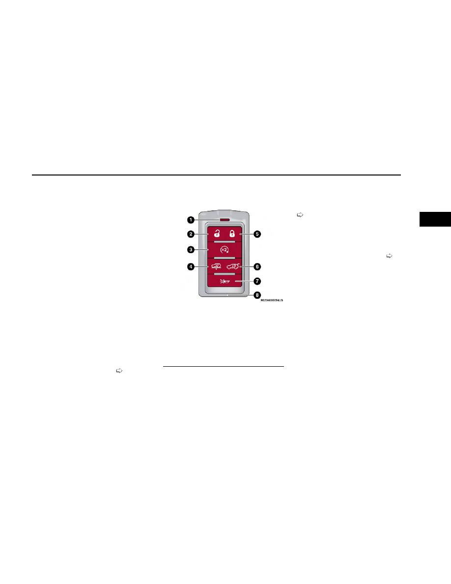
Your vehicle is equipped with a key fob which supports
Passive Entry, Remote Keyless Entry (RKE), Keyless
Enter ‘n Go™, Remote Air Suspension Lowering, and
Remote Start. The key fob allows you to lock or unlock
all doors and liftgate, as well as activate the Panic
Alarm from distances up to approximately 66 ft (20 m).
The key fob does not need to be pointed at the vehicle
to activate the system. The key fob also contains an
emergency key, which is stored in the rear of the key
fob.

NOTE:

In vehicles equipped with Remote Start, the key fob will
operate at distances up to 328 ft (100 m).

NOTE:

The key fob’s wireless signal may be blocked if the
key fob is located next to a mobile phone, laptop, or
other electronic device. This may result in poor
performance.

If your vehicle is equipped with a Wireless Charging
Pad, the key fob may not be detected if it is placed
within 6 inches (15 cm) of the pad

page 77.

With the ignition in the ON position and the vehicle
moving at 2 mph (4 km/h), all RKE commands are
disabled.

In case the ignition switch does not change positions
with the push of a button, the key fob may have a low or
fully depleted battery. A low key fob battery can be veri-
fied by referring to the instrument cluster, which will
display directions to follow.

For more information on ignition positions, see

page 21.

NOTE:

A low key fob battery condition may be indicated by a
message in the instrument cluster display, or by the
LED light on the key fob. If the LED key fob light no lon-
ger illuminates after a key fob button is pushed, then
the key fob battery requires replacement

page 348.

To Lock/Unlock The Doors And Liftgate

Push and release the unlock button on the key fob once
to unlock the driver’s door, or twice within five seconds
to unlock all the doors and liftgate. To lock all the doors
and liftgate, push the lock button once.

When the doors are unlocked, the turn signals will flash
and the illuminated entry system will be activated.
When the doors are locked, the turn signals will flash
and the horn will chirp.

NOTE:

If the vehicle is equipped with the Auto Relock fea-
ture, and is unlocked with the key fob, and no door
is opened within 60 seconds, the vehicle will relock
and the Vehicle Security system will arm
(if equipped). This feature can be enabled/disabled
within Uconnect Settings.

If one or more doors are open, or the liftgate is
open, the doors will lock. The doors will unlock
again automatically if the key fob is left inside the
passenger compartment, otherwise the doors will
stay locked.

Key Fob

1 — LED Indicator
2 — Unlock
3 — Remote Start
4 — Air Suspension Remote Lowering (If Equipped)
5 — Lock
6 — Power Liftgate
7 — Panic
8 — Emergency Key

17

2

All doors can be programmed to unlock on the first
push of the unlock button through Uconnect Settings

page 182.

Using The Panic Feature

To turn the Panic feature on or off, push the Panic but-
ton on the key fob. When the Panic feature is activated,
the turn signals will flash, the horn may pulse on and
off (if equipped with horn alarm), and the interior lights
will turn on.

The Panic feature will stay on for three minutes unless
you turn it off by either pushing the Panic button a sec-
ond time or drive the vehicle at a speed of 15 mph
(24 km/h) or greater.

NOTE:

The interior lights will turn off if you place the igni-
tion in the ON/RUN position while the Panic feature
is activated. However, the exterior lights and horn
(if equipped with horn alarm) will remain on.

You may need to be closer than 66 ft (20 m) from
the vehicle when using the key fob to turn off the
Panic feature due to the radio frequency noises
emitted by the system.

Key Left Vehicle Feature

If a valid key fob is no longer detected inside the vehicle
while the vehicle’s ignition system is in the ON/RUN or
START position, the message “Key Fob Has Left The
Vehicle” will be shown in the instrument cluster display
along with an interior chime. An exterior audible and
visual alert will also be activated to warn the driver.

The vehicle’s horn will rapidly chirp three times along
with a single flash of the vehicle’s exterior lights.

NOTE:

The doors have to be open and then closed in order
for the vehicle to detect a key fob. The Key Left
Vehicle feature will activate when the first door is
closed and no key fob is detected in the vehicle. If
the warning has been activated, and the other doors
are closed, no other warnings will be issued.

These alerts will not be activated in situations where
either the vehicle’s engine is left running with the
key fob inside, or the key fob’s wireless signals are
blocked.

Air Suspension (Remote Lowering Of

The Vehicle) — If Equipped

For easy entry and loading, your vehicle can
be lowered to Entry/Exit height by pushing
the key fob air suspension button two times.
When air suspension lowering is requested

using the key fob, the vehicle will send a series of
chirps and flashes (when enabled within Uconnect Set-
tings) to alert the customer that the operation has
begun and will continue these alerts until it success-
fully lowers.

The following conditions must be met for the vehicle to
lower remotely:

The vehicle must not already be in Entry/Exit (Park)
ride height.

The vehicle battery must be fully charged.

All doors must be closed.

The key fob must be out of the vehicle.

NOTE:

Ensure the vehicle is clear of all objects, pets, and
people prior to remote lowering.

Canceling Remote Lowering

Vehicle lowering can be canceled at anytime. When
vehicle lowering is canceled, the vehicle will raise up to
the next defined level and lock out the remote lowering
feature for five seconds before a new request can be
made.

To cancel vehicle lowering, push the key fob air suspen-
sion button one time during the lowering process. When
vehicle lowering is canceled, the horn will chirp two
times and the turn signals will flash four times. Once
raising is completed, the horn will chirp one time.

NOTE:

For more information on Air Suspension, see

page 125.

Replacing The Battery In The Key Fob

The replacement battery model is one CR2450 battery.

NOTE:

Customers are recommended to use a battery
obtained from Mopar®. Aftermarket coin battery
dimensions may not meet the original OEM coin
battery dimensions.

Perchlorate Material — special handling may apply.
See www.dtsc.ca.gov/hazardouswaste/perchlorate
for further information.

Do not touch the battery terminals that are on the
back housing or the printed circuit board.

Do not replace the coin battery if the LED on the key
fob above the top row buttons blinks when a button
is pressed. The coin battery should last a minimum
of three years with normal vehicle usage.

18

GETTING TO KNOW YOUR VEHICLE

1. Remove the emergency key by pushing the emer-

gency key release button (1) on the side of the key
fob, and pulling the emergency key (2) out with your
other hand.

2. Hold the key fob with the button side facing down,

and locate the small rectangular gap on the left side
between the housing and the back cover of the key
fob. Use a small flat-bladed tool to pry open the left
side of the fob cover while applying pressure until
the cover snaps open.

3. Next, locate the gap on the right side of the key fob,

which is positioned farther to the edge than the left
side gap. Pry open the right side, and remove the
back cover.

4. Remove the battery by using your thumb to slide the

battery downward and back toward the key ring.

NOTE:

You can also insert a screwdriver or similar tool into
the battery removal pocket to pry the battery out.

NOTE:

When replacing the battery, ensure the (+) sign on
the battery is facing upward. Avoid touching the new
battery with your fingers. Skin oils may cause bat-
tery deterioration. If you touch a battery, clean it
with rubbing alcohol.

Emergency Key Removal

1 — Emergency Key Release Button
2 — Emergency Key

Emergency Key Removed

Pry Apart Key Fob Halves

Key Fob Battery Location

Battery Removal Pocket

GETTING TO KNOW YOUR VEHICLE

19

2

5. Replace the battery by using your thumb to push

down and slide the battery under the small lip on
the top edge of the opening.

6. To assemble the key fob case, line up the top edge

of the back cover with the top of the fob, and press
the edges into the interlocking hinges until all edges
snap together with no large visual gaps.

7. Reinsert the emergency key until it locks into place.

NOTE:

The key fob battery should only be replaced by qualified
technicians. If the battery requires replacement, see an
authorized dealer.

WARNING!

The integrated key fob contains a coin cell battery.
Do not ingest the battery; there is a chemical burn
hazard. If the coin cell battery is swallowed, it can
cause severe internal burns in just two hours and
can lead to death.

(Continued)

WARNING!

If you think a battery may have been swallowed or
placed inside any part of the body, seek immediate
medical attention.

Keep new and used batteries away from children.
If the battery compartment does not close
securely, stop using the product and keep it away
from children.

Programming And Requesting

Additional Key Fobs

Programming the key fob may be performed by an
authorized dealer.

NOTE:

Once a key fob is programmed to a vehicle, it cannot
be repurposed and reprogrammed to another
vehicle.

Only key fobs that are programmed to the vehicle
electronics can be used to start and operate the
vehicle.

WARNING!

Always remove the key fobs from the vehicle and
lock all doors when leaving the vehicle
unattended.

For vehicles equipped with Keyless Enter ‘n Go™
Ignition, always remember to place the ignition in
the OFF position when exiting the vehicle.

Duplication of key fobs may be performed at an autho-
rized dealer. This procedure consists of programming a
blank key fob to the vehicle electronics. A blank key fob
is one that has never been programmed.

NOTE:

When having the Sentry Key Immobilizer system
serviced, bring all vehicle keys with you to an autho-
rized dealer.

Keys must be ordered to the correct key cut to
match the vehicle locks.

It is not mandatory to replace the key fob if a new
emergency key is needed, and vice versa.

SENTRY KEY

The Sentry Key Immobilizer system prevents unauthor-
ized vehicle operation by disabling the engine. The sys-
tem does not need to be armed or activated. Operation
is automatic, regardless of whether the vehicle is
locked or unlocked.

The system uses a key fob, keyless push button ignition
and a Radio Frequency (RF) receiver to prevent unau-
thorized vehicle operation. Therefore, only key fobs that
are programmed to the vehicle can be used to start and
operate the vehicle. The system cannot reprogram a
key fob obtained from another vehicle.

Key Fob Battery Replacement

20

GETTING TO KNOW YOUR VEHICLE

After placing the ignition in the ON/RUN position, the
Vehicle Security Light will turn on for three seconds for
a bulb check. If the light remains on after the bulb
check, it indicates that there is a problem with the elec-
tronics. In addition, if the light begins to flash after the
bulb check, it indicates that someone attempted to
start the engine with an invalid key fob. If a valid key fob
is used to start the engine but there is an issue with the
vehicle electronics, the engine will start and shut off
after two seconds.

NOTE:

If the keyless push button ignition fails to start, the key
fob may need to be moved around if it has been idle for
more than 5 minutes.

If the Vehicle Security Light turns on during normal
vehicle operation (vehicle running for longer than
10 seconds), it indicates that there is a fault in the elec-
tronics. Should this occur, have the vehicle serviced as
soon as possible by an authorized dealer.

CAUTION!

The Sentry Key Immobilizer system is not compatible
with some aftermarket Remote Start systems. Use of
these systems may result in vehicle starting problems
and loss of security protection.

All of the key fobs provided with your new vehicle have
been programmed to the vehicle electronics

page 348.

NOTE:

A key fob that has not been programmed is also consid-
ered an invalid key.

IGNITION SWITCH

KEYLESS ENTER ‘N GO™ IGNITION

This feature allows the driver to operate the ignition
switch with the push of a button as long as the key fob
is in the passenger compartment.

The START/STOP ignition button has several operating
modes that are labeled and will illuminate when in posi-
tion. These modes are OFF, ON/RUN, and START.

The push button ignition can be placed in the following
modes:

OFF

The engine is stopped

Some electrical devices (e.g. power locks, alarm,
etc.) are still available

ON/RUN

Driving position

All electrical devices are available (e.g. climate con-
trols, heated seats, etc.)

START

The engine will start (when foot is on the brake
pedal)

NOTE:

If the ignition position does not change with a push
of the ignition button, and the instrument cluster
displays a message such as “Key Fob Not
Detected”, the key fob may have a low or depleted
battery. In this situation, a backup method can be
used to operate the ignition switch. Put the nose
side of the key fob (side opposite of the emergency
key) against the START/STOP ignition button and
push to operate the ignition switch.

Replacement of the key fob battery is recommended.

START/STOP Ignition Button

1 — OFF
2 — ON/RUN

Depleted Key Fob Battery Procedure

GETTING TO KNOW YOUR VEHICLE

21

2

WARNING!

When exiting the vehicle, always remove the key
fob from the vehicle and lock your vehicle.

Never leave children alone in a vehicle, or with
access to an unlocked vehicle.

Allowing children to be in a vehicle unattended is
dangerous for a number of reasons. A child or oth-
ers could be seriously or fatally injured. Children
should be warned not to touch the parking brake,
brake pedal or the gear selector.

Do not leave the key fob in or near the vehicle, or
in a location accessible to children, and do not
leave the Keyless Enter ‘n Go™ Ignition in the
ON/RUN position. A child could operate power win-
dows, other controls, or move the vehicle.

Do not leave children or animals inside parked
vehicles in hot weather. Interior heat buildup may
cause serious injury or death.

CAUTION!

An unlocked vehicle is an invitation for thieves.
Always remove key fob from the vehicle and lock all
doors when leaving the vehicle unattended.

NOTE:

The key fob may not be detected by the vehicle Key-
less Enter ‘n Go™ system if it is located next to a
mobile phone, laptop or other electronic device;
these devices may block the key fob’s wireless sig-
nal and prevent the Keyless Enter ‘n Go™ system
from starting the vehicle.

For more information on the engine starting proce-
dure, see

page 113.

When opening the driver's door and the ignition is in
the ON/RUN position (engine not running), a chime
will sound to remind you to place the ignition in the
OFF position. In addition to the chime, the message
“Ignition ON” will display in the cluster.

REMOTE START

This system uses the key fob to start the
engine conveniently from outside the vehicle
while still maintaining security. The system has
a range of approximately 328 ft (100 m).

Remote Start is used to defrost windows in cold
weather, and to reach a comfortable climate in all ambi-
ent conditions before the customer enters the vehicle.

NOTE:

Obstructions between the vehicle and key fob may
reduce this range

page 348.

WARNING!

Do not start or run an engine in a closed garage or
confined area. Exhaust gas contains carbon mon-
oxide which is odorless and colorless. Carbon mon-
oxide is poisonous and can cause serious injury or
death when inhaled.

Keep key fobs away from children. Operation of the
Remote Start system, windows, door locks or other
controls could cause serious injury or death.

HOW TO USE REMOTE START

Push and release the Remote Start button on the key
fob twice within five seconds. The vehicle doors will
lock, the parking lights will flash, and the horn will chirp
twice (if programmed). Then, the engine will start, and
the vehicle will remain in the Remote Start mode for a
15 minute cycle. Pushing the Remote Start button a
third time shuts the engine off.

NOTE:

With Remote Start, the engine will only run for
15 minutes.

Remote Start can only be used twice.

If an engine fault is present or fuel level is low, the
vehicle will start and then shut down in 10 seconds.

The parking lights will turn on and remain on during
Remote Start mode.

Headlight animation (if equipped) will occur when
Remote Start is activated, if “Headlight Illumination
On Approach” is enabled within Uconnect Settings.

For security, power window and power sunroof
operation (if equipped) are disabled when the
vehicle is in the Remote Start mode.

The ignition must be placed in the ON/RUN position
before the Remote Start sequence can be repeated
for a third cycle.

All of the following conditions must be met before the
engine will remote start:

Gear selector in PARK

Doors closed

Hood closed

Liftgate closed

22

GETTING TO KNOW YOUR VEHICLE

Hazard switch off

Brake switch inactive (brake pedal not pressed)

Battery at an acceptable charge level

System not disabled from previous Remote Start
event

Vehicle Security Light flashing

Ignition in OFF position

Panic button is not pushed

Fuel level meets minimum requirement

Vehicle Security system is not signaling an intrusion

Malfunction Indicator Light (MIL) is not illuminated

WARNING!

Do not start or run an engine in a closed garage or
confined area. Exhaust gas contains carbon mon-
oxide which is odorless and colorless. Carbon mon-
oxide is poisonous and can cause serious injury or
death when inhaled.

Keep key fobs away from children. Operation of the
Remote Start system, windows, door locks or other
controls could cause serious injury or death.

TO EXIT REMOTE START MODE

To drive the vehicle after starting the Remote Start sys-
tem, either push and release the unlock button on the
key fob to unlock the doors, or unlock the vehicle using
Keyless Enter ‘n Go™ — Passive Entry via the door
handles, and disarm the Vehicle Security system
(if equipped). Then, prior to the end of the 15 minute
cycle, push and release the START/STOP ignition
button.

The Remote Start system will turn the engine off if the
Remote Start button on the key fob is pushed again, or
if the engine is allowed to run for the entire 15 minute
cycle. Once the ignition is placed in the ON/RUN posi-
tion, the climate controls will resume previously set
operations (temperature, blower control, etc.).

NOTE:

To avoid unintentional shutdowns, the system will
disable for two seconds after receiving a valid
Remote Start request.

For vehicles equipped with the Keyless Enter ‘n Go™
— Passive Entry feature, the message “Remote Start
Active — Push Start Button” will display in the instru-
ment cluster display until you push the START/STOP
ignition button.

REMOTE START FRONT DEFROST
ACTIVATION — IF EQUIPPED

When Remote Start is active, and the outside ambient
temperature is 40°F (4.5°C) or below, the system will
automatically activate front defrost for 15 minutes or
less. The timing is dependent on the ambient tempera-
ture. Once the timer expires, the system will automati-
cally adjust the settings depending on ambient condi-
tions. See “Remote Start Comfort Systems —
If Equipped” in the next section for detailed operation.

REMOTE START COMFORT
SYSTEMS — IF EQUIPPED

When Remote Start is activated, the front and rear
defroster will automatically turn on in cold weather con-
ditions. The heated steering wheel and driver heated
seat feature will turn on if programmed in the Comfort
menu screen within Uconnect Settings

page 182.

In warm weather, the driver vented seat feature will
automatically turn on when Remote Start is activated, if
programmed in the Comfort menu screen. The vehicle
will adjust the climate control settings depending on
the outside ambient temperature.

NOTE:

If the vehicle is equipped with a rear climate system, it will
remain off to allow for optimal front row performance.

Automatic Temperature Control (ATC) — If Equipped

The climate controls will automatically adjust to the
optimal temperature and mode settings depending on
the outside ambient temperature. This will occur until
the ignition is placed in the ON/RUN position where the
climate controls will resume their previous settings.

Manual Temperature Control (MTC) — If Equipped

In ambient temperatures of 40°F (4.5°C) or below,
the climate settings will default to maximum heat,
with fresh air entering the cabin. If the front defrost
timer expires, the vehicle will enter Mix mode.

In ambient temperatures from 40°F (4.5°C) to
78°F (26°C), the climate settings will be based on
the last settings selected by the driver.

In ambient temperatures of 78°F (26°C) or above,
the climate settings will default to MAX A/C, Bi-Level
mode, with Recirculation on.

For more information on ATC, MTC, and climate control
settings, see

page 62.

GETTING TO KNOW YOUR VEHICLE

23

2

NOTE:

These features will stay on through the duration of
Remote Start, or until the ignition is placed in the
ON/RUN position. The climate control settings will
change, and exit the automatic defaults, if manually
adjusted by the driver while the vehicle is in Remote
Start mode. This includes turning the climate controls
off using the OFF button.

REMOTE START WINDSHIELD
WIPER DE-ICER ACTIVATION —
IF EQUIPPED

When Remote Start is active and the outside ambient
temperature is less than 33°F (0.6°C), the Windshield
Wiper De-Icer will activate. Exiting Remote Start will
resume its previous operation. If the Windshield Wiper
De-Icer was active, the timer and operation will continue.

REMOTE START ABORT MESSAGE

One of the following messages will display in the instru-
ment cluster display if the vehicle fails to remote start
or exits Remote Start prematurely:

Remote Start Canceled — Door Open

Remote Start Canceled — Hood Open

Remote Start Canceled — Liftgate Open

Remote Start Canceled — Fuel Low

Remote Start Canceled — Time Expired

Remote Start Canceled — System Fault

Remote Start Disabled — Start Vehicle to Reset

The instrument cluster display message stays active
until the ignition is placed in the ON/RUN position.

VEHICLE SECURITY SYSTEM —
IF EQUIPPED

The Vehicle Security system monitors the vehicle doors,
hood, liftgate, and the Keyless Enter ‘n Go™ Ignition for
unauthorized operation. While the Vehicle Security sys-
tem is armed, interior switches for door locks and lift-
gate release handle are disabled. If something triggers
the alarm, the Vehicle Security system will provide the
following audible and visible signals:

The horn will pulse

The turn signals will flash

The Vehicle Security Light in the instrument cluster
will flash

TO ARM THE SYSTEM

Follow these steps to arm the Vehicle Security system:

1. Make sure the vehicle’s ignition is placed in the OFF

position.

For vehicles equipped with Keyless Entry, make
sure the vehicle’s keyless ignition system is OFF.

2. Perform one of the following methods to lock the

vehicle:

Push the lock button on one of the front interior
power door lock switches with the driver and/or
passenger door open.

Touch the lock button on the exterior Passive
Entry door handle with a valid key fob available in
the same exterior zone

page 27.

Push the lock button on the key fob.

3. If any doors are open, close them.

When the Vehicle Security system is armed, the Vehicle
Security Light (located in the lower right portion of the
instrument cluster display) will begin to flash every two
seconds until it is disarmed.

NOTE:

If the system is armed by pushing the lock button on
the interior door panel, the Vehicle Security Light will
flash rapidly for about 15 seconds once the door is
closed, then slow down to every two seconds.

Pushing a lock button on the rear interior power
door lock switches will not arm the Vehicle Security
system.

TO DISARM THE SYSTEM

The Vehicle Security system can be disarmed using any
of the following methods:

Push the unlock button on the key fob.

Grab the Passive Entry door handle to unlock the
door

page 27.

Cycle the ignition out of the OFF position to disarm
the system.

NOTE:

The driver's door key cylinder cannot arm or disarm
the Vehicle Security system. Use of the door key cyl-
inder when the alarm is armed will sound the alarm
when the door is opened.

The Vehicle Security system remains armed when
the power liftgate is opened using the liftgate button
on the key fob. If someone enters the vehicle
through the opened liftgate, then opens any door
from the inside, the alarm will sound.

24

GETTING TO KNOW YOUR VEHICLE

If Passive Entry (if equipped) is used to unlock the
liftgate, the Vehicle Security system is disarmed and
the rest of the vehicle doors will remain locked
unless all doors are set to unlock on first press
within Uconnect Settings.

When the Vehicle Security system is armed, the inte-
rior power door lock switches will not unlock the
doors.

The Vehicle Security system is designed to protect your
vehicle. However, you can create conditions where the
system will give you a false alarm. If one of the previ-
ously described arming sequences has occurred, the
Vehicle Security system will arm regardless of whether
you are in the vehicle or not. If you remain in the vehicle
and open a door, the alarm will sound. If this occurs,
disarm the Vehicle Security system.

If the Vehicle Security system is armed and the battery
becomes disconnected, the Vehicle Security system will
remain armed when the battery is reconnected; the
exterior lights will flash, and the horn will sound. If this
occurs, disarm the Vehicle Security system.

REARMING OF THE SYSTEM

If something triggers the alarm and no action is taken
to disarm it, the Vehicle Security system will turn the
horn off after a 29 second cycle (with five seconds
between cycles and up to eight cycles if the trigger
remains active) and then rearm itself.

SECURITY SYSTEM MANUAL
OVERRIDE

The Vehicle Security system will not arm if you lock the
doors using the manual door lock, or an emergency
lock lever

page 26.

TAMPER ALERT

If something has triggered the Vehicle Security system
in your absence, the horn will sound three times and
the exterior lights will blink three times when you dis-
arm the Vehicle Security system.

DELUXE VEHICLE SECURITY SYSTEM —
IF EQUIPPED

The Deluxe Vehicle Security system monitors the doors,
hood latch, and liftgate for unauthorized entry and the
ignition switch for unauthorized operation. The system
also includes a dual function intrusion sensor and
vehicle tilt sensor. The intrusion sensor monitors the
vehicle interior for motion. The vehicle tilt sensor moni-
tors the vehicle for any tilting actions (tow away, tire
removal, ferry transport, etc.).

If a perimeter violation triggers the security system, the
horn will sound for 29 seconds and the exterior lights
will flash followed by approximately five seconds of no
activity. This will continue for eight cycles if no action is
taken to disarm the system.

TO ARM THE SYSTEM

Follow these steps to arm the security system:

1. If any doors, windows, or the sunroof (if equipped)

are open, close them.

2. Make sure the vehicle ignition system is OFF.

3. Perform one of the following methods to lock the

vehicle:

Push lock on the interior power door lock switch
with the driver and/or passenger door open.

Touch the lock button on the exterior Passive
Entry door handle with a key fob available in the
same exterior zone

page 27.

Push the lock button on the key fob.

NOTE:

When armed, the interior motion sensor detects
movement within the vehicle's interior, including
moving objects (i.e. people and pets) and air cur-
rents through open windows or the sunroof. The
windows and sunroof should be closed, and moving
objects should not be left in the vehicle when the
intrusion detection is armed, otherwise false alarms
can occur.

Once the security system is armed, it remains in
that state until you disarm it by following either of
the disarming procedures described. If a power loss
occurs after arming the system, you must disarm
the system after restoring power to prevent alarm
activation.

The ultrasonic intrusion sensor (motion detector)
actively monitors your vehicle every time you arm
the Vehicle Security system. If you prefer, you can
turn off the ultrasonic intrusion sensor when arming
the Vehicle Security system. To do so, push the lock
button on the key fob three times within 15 seconds
of arming the system (while the Vehicle Security
Light is flashing rapidly). The vehicle will remain
locked but will disable the alarm in the case of
repeated false alarms due to ambient conditions.

GETTING TO KNOW YOUR VEHICLE

25

2

TO DISARM THE SYSTEM

The Vehicle Security system can be disarmed using any
of the following methods:

Push the unlock button on the key fob.

Grab the Passive Entry door handle to unlock the
door

page 27.

Cycle the vehicle ignition system out of the OFF posi-
tion by pushing the START/STOP ignition button
(requires at least one valid key fob in the vehicle).

NOTE:

The driver's door key cylinder and the liftgate button
on the key fob cannot arm or disarm the Vehicle
Security system.

The Vehicle Security system remains armed during
power liftgate entry. If a valid key fob or Passive
Entry is used to open the liftgate, the motion sens-
ing will be suppressed until after the liftgate is
closed. If someone enters the opened vehicle
through the liftgate, then opens any door, the alarm
will sound.

When the Vehicle Security system is armed, the inte-
rior power door lock switches will not unlock the
doors.

The ultrasonic intrusion sensor (motion detector)
actively monitors your vehicle every time you arm
the Vehicle Security system. If you prefer, you can
turn off the ultrasonic intrusion sensor when arming
the Vehicle Security system. To do so, push the lock
button on the key fob three times within 15 seconds
of arming the system (while the Vehicle Security
Light is flashing rapidly). The vehicle will remain
locked but will disable the alarm in the case of
repeated false alarms due to ambient conditions.

The Vehicle Security system is designed to protect your
vehicle; however, you can create conditions where the
system will give you a false alarm. If one of the previ-
ously described arming sequences has occurred, the
Vehicle Security system will arm regardless of whether
you are in the vehicle or not. If you remain in the vehicle
and open a door, the alarm will sound. If this occurs,
disarm the Vehicle Security system.

If the Vehicle Security system is armed and the battery
becomes disconnected, the Vehicle Security system will
remain armed when the battery is reconnected; the
exterior lights will flash and the horn will sound. If this
occurs, disarm the Vehicle Security system.

SECURITY SYSTEM MANUAL
OVERRIDE

The Vehicle Security system will not arm if you lock the
doors using the manual door lock, or an emergency
lock lever

page 26.

DOORS

MANUAL DOOR LOCKS

The front doors can be manually unlocked with a single
pull of the inside door handle. The driver’s door can
also be manually locked/unlocked by inserting the
emergency key into the lock cylinder on the outside
door handle.

The rear doors can be manually unlocked with a double
pull of the inside door handle.

All doors except the driver’s door can be manually
locked by inserting the emergency key into the emer-
gency lock lever and sliding the lever upward. The emer-
gency lock lever is located on the door latch face of
each door.

Driver’s Door Cylinder Lock

Emergency Lock Lever

26

GETTING TO KNOW YOUR VEHICLE

NOTE:

The emergency lock lever is only accessible when
the door is open.

Manually locking the vehicle will not arm the Vehicle
Security system.

WARNING!

For personal security and safety in the event of a
collision, lock the vehicle doors before you drive as
well as when you park and leave the vehicle.

When exiting the vehicle, always make sure the
ignition is in the OFF position, remove the key fob
from the vehicle and lock your vehicle.

Never leave children alone in a vehicle, or with
access to an unlocked vehicle. Allowing children to
be in a vehicle unattended is dangerous for a num-
ber of reasons. A child or others could be seriously
or fatally injured. Children should be warned not to
touch the parking brake, brake pedal or the gear
selector.

Do not leave the key fob in or near the vehicle, or
in a location accessible to children, and do not
leave the Keyless Enter ‘n Go™ Ignition in the
ON/RUN position. A child could operate power win-
dows, other controls, or move the vehicle.

POWER DOOR LOCKS

The power door lock buttons are located on each front
door panel. Use these buttons to lock or unlock all
doors and liftgate.

When the doors are locked, an indicator light in the lock
button will illuminate.

The driver’s door will unlock automatically if the key fob
is detected inside the vehicle when the door lock button
on the front door panel is used to lock the door, then
the door is closed. The horn will also chirp to alert the
driver. This will occur for two attempts. On the third
attempt, the doors will lock even if the key fob is inside.

NOTE:

If the key fob is located next to a mobile phone, laptop,
or other electronic device, the wireless signal may get
blocked, and the driver’s door may not unlock
automatically.

If the door lock switch is pushed while the ignition is in
ON/RUN and the driver's door is open, the doors will
not lock.

Rear Passenger Power Door Locks

Power door lock buttons are located on each rear door
trim panel. Push the lock button to lock the rear door or
push the unlock button to unlock the rear door.

POWER SIDE STEPS — IF EQUIPPED

The Power Side Steps will extend for easier entry and
exit of the vehicle.

When configured for “Auto” mode, the Power Side Steps
will deploy when any of the doors are opened, and they
will retract when the doors are closed. This mode can
be turned on or off in the Uconnect Settings

page 182.

NOTE:

When enabled within Uconnect Settings, the Power
Side Steps can also be manually extended or
retracted by pressing the Power Side Step button on
the Controls menu of the Vehicle screen.

If the vehicle speed exceeds 5 mph (8 km/h), the
steps will retract.

KEYLESS ENTER ‘N GO™ —
PASSIVE ENTRY

Use this QR code to access your digital
experience.

The Passive Entry system is an enhance-
ment to the vehicle’s Remote Keyless
Entry (RKE) system and a feature of Key-
less Enter ‘n Go™. This feature allows you
to lock and unlock the vehicle’s door(s) without having to
push the key fob lock or unlock buttons.

If equipped, the rear doors will also have Passive Entry
capabilities.

Power Door Lock Switches

Scan me

GETTING TO KNOW YOUR VEHICLE

27

2

NOTE:

Passive Entry may be programmed on/off through
Uconnect Settings

page 182.

The key fob may not be detected by the vehicle Pas-
sive Entry system if it is located next to a mobile
phone, laptop or other electronic device; these
devices may block the key fob's wireless signal and
prevent the Passive Entry handle from locking/
unlocking the vehicle.

Passive Entry Unlock initiates illuminated approach
(low beams, license plate lamp, parking lights, door
handle pocket lights [if equipped]) for whichever
duration is set between 0, 30, 60 or 90 seconds.
Passive Entry Unlock also initiates two flashes of the
turn signals.

If wearing gloves, if it has been raining/snowing, or
if there is salt/dirt covering the Passive Entry door
handle, the unlock and lock sensitivity can be
affected, resulting in a slower response time.

The doors may lock and unlock when water is
sprayed on the Passive Entry door handles, if the
key fob is located outside of the vehicle within 5 ft
(1.5 m) of the handle.

Passive Entry lock initiates one horn chirp and one
flash of turn signals. These settings can be pro-
grammed on/off within Uconnect Settings

page 182.

If the vehicle is unlocked by Passive Entry and no
door is opened within 60 seconds, the vehicle will
relock and will arm the Vehicle Security system (if
equipped).

To Unlock From The Driver Or Passenger Side

With a valid Passive Entry key fob within 5 ft (1.5 m) of the
door handle, grab the handle to unlock the vehicle. Grab-
bing the driver’s door handle will unlock the driver door
automatically. Grabbing the front passenger door handle
(or a rear handle when equipped with four-door Passive
Entry) will unlock all doors and the liftgate automatically.

NOTE:

Either the driver’s door only or all doors will unlock
when you grab hold of the front driver’s door handle,
depending on the selected setting in the Uconnect
system

page 182.

All doors will unlock when the front passenger (or a
rear door when equipped with four-door Passive
Entry) door handle is grabbed regardless of the driv-
er’s door unlock preference setting.

Frequency Operated Button Integrated Key (FOBIK-Safe)

To minimize the possibility of unintentionally locking a
Passive Entry key fob inside your vehicle, the Passive
Entry system is equipped with an automatic door

unlock feature which will function if the ignition switch
is in the OFF position.

There are five situations that trigger a FOBIK-Safe
search in any Passive Entry vehicle:

A lock request is made by a valid Passive Entry key
fob while a door is open.

A lock request is made by the Passive Entry door
handle while a door is open.

A lock request is made by the door panel switch
while the door is open.

When the Vehicle Security system is in pre-arm or
armed status and the liftgate transitions from
opened to closed.

When the liftgate transitions from open to closed
and Remote Start is active.

When any of these situations occur, after all open doors
are shut, the FOBIK-Safe search will be executed. If it
detects a Passive Entry key fob inside the vehicle, the
vehicle will unlock and alert the customer.

NOTE:

The vehicle will only unlock the doors when a valid Pas-
sive Entry key fob is detected inside the vehicle. The
vehicle will not unlock the doors when any of the follow-
ing conditions are true:

The doors are manually locked using the emergency
lock lever.

Three attempts are made to lock the doors using
the door panel switch and then the doors are
closed.

There is a valid Passive Entry key fob outside the
vehicle within 5 ft (1.5 m) of a Passive Entry door
handle.

Grab The Door Handle To Unlock

28

GETTING TO KNOW YOUR VEHICLE

To Lock The Vehicle’s Doors And Liftgate

With one of the vehicle’s Passive Entry key fobs within
5 ft (1.5 m) of a Passive Entry door handle, touch the
lock icon on the door handle to lock all four doors and
liftgate.

NOTE:

Do NOT grab the door handle when touching the lock
icon. This could unlock the door(s).

NOTE:

After touching the door handle lock icon, you must
wait two seconds before you can lock or unlock the
doors using any Passive Entry door handle. This is
done to allow you to check if the vehicle is locked by
pulling the door handle, without the vehicle
unlocking.

If Passive Entry is disabled using the Uconnect Set-
tings, the key fob protection described in "Frequency
Operated Button Integrated Key (FOBIK-Safe)"
remains active/functional.

The Passive Entry system will not operate if the key
fob battery is depleted.

To Unlock/Enter The Liftgate

The liftgate Passive Entry unlock feature is built into the
electronic liftgate release button. With a valid Passive
Entry key fob within 5 ft (1.5 m) of the liftgate, push the
electronic liftgate release handle for a power open on
vehicles equipped with Power Liftgate. Push the electronic
liftgate button and lift for Manual Liftgate vehicles.

To Lock The Liftgate

With a valid Passive Entry key fob within 5 ft (1.5 m) of
the liftgate, push the Passive Entry lock button located
on the outside liftgate door handle.

NOTE:

The liftgate Passive Entry lock button will lock all doors
and the liftgate

page 348.

Touch The Door Handle Lock Icon To Lock

Do NOT Grab The Door Handle When Locking

Liftgate Entry

1 — Passive Entry Lock Button
2 — Electronic Liftgate Release Handle

GETTING TO KNOW YOUR VEHICLE

29

2

AUTOMATIC UNLOCK DOORS ON
EXIT

The doors will unlock automatically on vehicles with
power door locks after the following sequence of
actions:

1. The Automatic Unlock Doors On Exit feature is

enabled within Uconnect Settings

page 182.

2. All doors are closed.

3. The gear selector was not in PARK, then is placed in

PARK.

4. Any door is opened.

AUTOMATIC DOOR LOCKS —
IF EQUIPPED

The auto door lock feature default condition is enabled.
When enabled, the door locks will lock automatically
when the vehicle speed exceeds 15 mph (24 km/h).
The auto door lock feature is enabled or disabled by an
authorized dealer per written request of the customer.
Please see an authorized dealer for service.

CHILD-PROTECTION DOOR LOCK
SYSTEM — REAR DOORS

To provide a safer environment for small children riding
in the rear seats, the rear doors are equipped with a
Child-Protection Door Lock system.

To use the system, open each rear door, use a flat-
blade screwdriver (or emergency key) and rotate the
dial to the lock or unlock position. When the system on
a door is engaged, that door can only be opened by
using the outside door handle even if the inside door
lock is in the unlocked position.

NOTE:

When the Child-Protection Door Lock system is
engaged, the door can be opened only by using the
outside door handle even though the inside door
lock is in the unlocked position.

After disengaging the Child-Protection Door Lock
system, always test the door from the inside to
make certain it is in the unlocked position.

After engaging the Child-Protection Door Lock sys-
tem, always test the door from the inside to make
certain it is in the locked position.

WARNING!

Avoid trapping anyone in a vehicle in a collision.
Remember that the rear doors can only be opened
from the outside with the Child-Protection locks
engaged (locked).

NOTE:

Always use this device when carrying children. After
engaging the child lock on both rear doors, check for
effective engagement by trying to open a door with the
internal handle. Once the Child-Protection Door Lock
system is engaged, it is impossible to open the doors
from inside the vehicle. Before getting out of the
vehicle, be sure to check that there is no one left
inside.

STEERING WHEEL

POWER TILT/TELESCOPING
STEERING COLUMN

This feature allows you to tilt the steering column
upward or downward. It also allows you to lengthen or
shorten the steering column. The power tilt/telescoping
steering column control is located below the multifunc-
tion lever on the steering column.

Child-Protection Door Lock Function

Power Tilt/Telescoping Steering Control Location

30

GETTING TO KNOW YOUR VEHICLE

Use the four-way control to adjust the steering column.

NOTE:

For vehicles equipped with Driver Memory Settings, use
the key fob or the memory switch on the driver's door
trim panel to return the tilt/telescopic steering column
to saved positions

page 31.

WARNING!

Do not adjust the steering column while driving.
Adjusting the steering column while driving or driving
with the steering column unlocked, could cause the
driver to lose control of the vehicle. Failure to follow
this warning may result in serious injury or death.

HEATED STEERING WHEEL

The steering wheel contains a heating element
that helps warm your hands in cold weather.
The heated steering wheel has three tempera-
ture settings. Once the heated steering wheel

has been turned on, it will stay on until the operator turns
it off. The heated steering wheel may not turn on when it
is already warm.

The heated steering wheel control button is located on the
left side of the radio screen or within the Uconnect sys-
tem. You can gain access to the control button on the top
left side of the screen by tapping the temperature con-
trols, which will provide a quick drop-down menu contain-
ing the controls, or through the Controls menu of the
touchscreen. If your vehicle is not equipped with the but-
ton on the side of the radio, you can also access the con-
trol button through the Climate menu.

Press the heated steering wheel button once to turn
the HI setting on.

Press the heated steering wheel button a second
time to turn the MED setting on.

Press the heated steering wheel button a third time
to turn the LO setting on.

Press the heated steering wheel button a fourth
time to turn the heating elements off.

NOTE:

The engine must be running for the heated steering
wheel to operate.

For information on use with the Remote Start system,
see

page 23.

WARNING!

Persons who are unable to feel pain to the skin
because of advanced age, chronic illness, diabetes,
spinal cord injury, medication, alcohol use, exhaus-
tion, or other physical conditions must exercise care
when using the steering wheel heater. It may cause
burns even at low temperatures, especially if used for
long periods.

Do not place anything on the steering wheel that
insulates against heat, such as a blanket or steer-
ing wheel covers of any type and material. This
may cause the steering wheel heater to overheat.

DRIVER AND PASSENGER MEMORY
SETTINGS — IF EQUIPPED

This feature allows the driver, and if equipped, also the
front passenger to save up to two different memory
profiles for easy recall through a memory switch.

Each memory profile saves desired position settings for
the following features:

Driver’s Side

Seat position

Easy entry/exit seat (if equipped)

Side mirrors

Power tilt and telescopic steering column

Power adjustable pedals (if equipped)

A set of desired radio station presets

Passenger’s Side (If Equipped)

Seat position

The memory settings switches are located on the front
door panels, next to the door handle, and consists of
two or three buttons, depending on trim level:

The (1) and (2) buttons which are used to recall
either of two saved memory profiles

The set (S) button (Wagoneer models only), which is
used to activate the memory save function

Wagoneer Memory Settings Buttons

GETTING TO KNOW YOUR VEHICLE

31

2

NOTE:

Your vehicle is equipped with two key fobs, each can
be linked to either driver’s side memory position
1 or 2.

Front passenger memory settings cannot be linked
to a key fob.

PROGRAMMING THE MEMORY
FEATURE

To create a new memory profile, perform the following:

NOTE:

Saving a new memory profile will erase the selected
profile from memory.

Wagoneer

1. Place the vehicle’s ignition in the ON/RUN position

(do not start the engine).

2. Adjust all memory profile settings to desired prefer-

ences (i.e., seat, side mirror, power tilt and tele-
scopic steering column, and radio station presets).

3. Push and release the set (S) button on the memory

switch.

4. Within five seconds, push and release either of the

memory buttons (1) or (2). The instrument cluster
display will indicate which memory position has
been set.

Grand Wagoneer

1. Place the vehicle’s ignition in the ON/RUN position

(do not start the engine).

2. Adjust all memory profile settings to desired prefer-

ences (i.e., seat, side mirror, power tilt and tele-
scopic steering column, and radio station presets).

3. Press memory button (1) or (2) for two or more sec-

onds. The instrument cluster display will indicate
which memory position has been set.

NOTE:

Memory profiles can be set without the vehicle in PARK,
but the vehicle must be below 5 mph (8 km/h) to recall
a memory profile.

LINKING AND UNLINKING THE KEY
FOB TO MEMORY

Your key fobs can be programmed to recall one of two
saved driver’s side memory profiles.

NOTE:

Before programming your key fobs you must select the
“Personal Settings Linked To Key Fob” feature through
the Uconnect Settings

page 182.

To program your key fobs, perform the following:

Wagoneer

1. Place the vehicle’s ignition in the OFF position.

2. Select a desired driver’s side memory profile, 1 or 2.

3. Once the profile has been recalled, push and

release the set (S) button on the memory switch.

4. Within five seconds, push and release button (1) or

(2) accordingly. “Memory Profile Set” (1 or 2) will
display in the instrument cluster.

5. Push and release the lock button on the key fob

within 10 seconds.

NOTE:

Your key fobs can be unlinked from your driver’s side
memory settings by pushing the set (S) button, and
within 10 seconds, pushing the unlock button on the
key fob.

Grand Wagoneer

1. Place the vehicle’s ignition in the OFF position.

2. Recall the desired memory profile (1 or 2).

3. Press the memory button (1) or (2) (according to the

previous selection) for two seconds or more, and
release.

4. Push and hold the lock button on the key fob within

10 seconds.

NOTE:

Your key fobs can be unlinked from your driver’s side
memory settings by pushing the memory button (1) or
(2) for two seconds or more and releasing, and then
within 10 seconds, pushing and holding the unlock but-
ton on the key fob.

Grand Wagoneer Memory Settings Buttons

32

GETTING TO KNOW YOUR VEHICLE

MEMORY POSITION RECALL

NOTE:

Memory Recall is available when not in PARK, if the
vehicle speed is below 5 mph (8 km/h).

To recall a memory settings using the memory
switches, push memory button (1) or (2) on the
memory switch.

To recall the driver’s side memory settings using the
key fob, push the unlock button on the key fob
linked to memory position 1 or 2.

A recall can be canceled by pushing any of the memory
buttons during a recall, or by pushing any of the seat
adjustment switches. When a recall is canceled, the
seat and power tilt/telescopic steering column will stop
moving. A delay of one second will occur before another
recall can be selected.

SEATS

Seats are a part of the Occupant Restraint system of
the vehicle.

WARNING!

It is dangerous to ride in a cargo area, inside or
outside of a vehicle. In a collision, people riding in
these areas are more likely to be seriously injured
or killed.

Do not allow people to ride in any area of your
vehicle that is not equipped with seats and seat
belts. In a collision, people riding in these areas
are more likely to be seriously injured or killed.

(Continued)

WARNING!

Be sure everyone in your vehicle is in a seat and
using a seat belt properly.

MANUAL ADJUSTMENT REAR
SEATS

WARNING!

Do not place luggage or cargo higher than the top of
the seatback. This could impair visibility or become a
dangerous projectile in a sudden stop or collision.

NOTE:

You may experience deformation in the seat cushion
from the seat belt buckles if the seats are left folded for
an extended period of time. This is normal and by sim-
ply unfolding the seats to the open position, over time
the seat cushion will return to its normal shape.

Second Row Bench Seat — If Equipped

SECOND ROW BENCH SEAT FORWARD/
REARWARD ADJUSTMENT

Lift up on the adjusting bar located at the front of the
seat near the floor and release it when the seat is at
the desired position. Then, using body pressure, move
forward and rearward on the seat to be sure that the
seat adjusters have latched.

SECOND ROW BENCH SEAT RECLINE
ADJUSTMENT

To recline, lean forward slightly and lift the lever located
on the outboard side of the seat. Then, push the seat rear-
ward to the desired position and release the lever. To
return the seatback to its normal position, lean forward
and lift the lever. To ensure the seatback is latched, use
body pressure to lean forward and rearward.

Rear Seat Adjustment Bar

Rear Seat Recline Lever

GETTING TO KNOW YOUR VEHICLE

33

2

To recline the center seat, pull the recline strap located
on the seatback, and move forward or backward as
desired. Release the strap when the desired seat posi-
tion has been reached.

WARNING!

Do not ride with the seatback reclined so that the
shoulder belt is no longer resting against your chest.
In a collision you could slide under the seat belt,
which could result in serious injury or death.

SECOND ROW BENCH FOLD FLAT SEAT

To provide additional storage area, each rear seat can
be folded flat. This allows for extended cargo space and
still maintains some rear seating room.

NOTE:

Prior to folding the rear seat, it may be necessary to
position the front seat to its mid-track position espe-
cially if the seat is equipped with Rear Seat Entertain-
ment. Also, be sure that the front seats are fully upright
and positioned forward. This will allow the rear seat to
fold down easily.

To lower the seatback, pull upward on the recline lever
located on the outboard side of the seat, and let the
seatback fold forward automatically.

To lower the center seatback, pull the recline strap,
located on the left side of the seatback, and let the
seatback fold forward automatically.

To raise the seatback, fold the seatback up into its origi-
nal position and lock it into place.

WARNING!

Be certain that the seatback is securely locked into
position. If the seatback is not securely locked into
position the seat will not provide the proper stability
for child seats and/or passengers. An improperly
latched seat could cause serious injury.

Center Seat Recline Strap

Second Row Bench Seat Folded Flat

Center Seat Recline Strap

34

GETTING TO KNOW YOUR VEHICLE

SECOND ROW BENCH SEAT EASY ACCESS
FOR THIRD ROW

The second row bench seats can slide forward to allow
passengers to easily access the third row seats.

Press the easy entry button located on the outboard
side of the seatback. Once pressed, the seat will pitch
forward, allowing the seat to slide forward.

To return the seat to a sitting position, push the seat-
back rearward until the seat locks.

Emergency Straps

In the event that the vehicle loses power, the Easy Entry
buttons will not function. There are emergency straps
located on the back of the second row outboard seats
to allow the third row occupants to manually fold the
seats flat to exit the vehicle.

Pull the emergency straps to fold the second row seat
flat.

Second Row Captain’s Chairs —

If Equipped

SECOND ROW CAPTAIN’S CHAIRS
FORWARD/REARWARD ADJUSTMENT

Lift up on the adjusting bar located at the front of the
seat near the floor and release it when the seat is at
the desired position. Then, using body pressure, move
forward and rearward on the seat to be sure that the
seat adjusters have latched.

SECOND ROW CAPTAIN’S CHAIRS RECLINE
ADJUSTMENT

To recline, lean forward slightly and lift the lever located
on the outboard side of the seat. Then, push the seat rear-
ward to the desired position and release the lever. To
return the seatback to its normal position, lean forward
and lift the lever. To ensure the seatback is latched, use
body pressure to lean forward and rearward.

Bench Seat Easy Entry Button

Emergency Straps

Rear Seat Adjustment Bar

Rear Seat Recline Lever

GETTING TO KNOW YOUR VEHICLE

35

2

WARNING!

Do not ride with the seatback reclined so that the
shoulder belt is no longer resting against your chest.
In a collision you could slide under the seat belt,
which could result in serious injury or death.

SECOND ROW CAPTAIN’S CHAIRS FOLD FLAT
SEATS

The second row seatbacks can be folded flat to carry
cargo.

NOTE:

Prior to folding the rear seat, it may be necessary to posi-
tion the front seat to its mid-track position especially if the
seat is equipped with Rear Seat Entertainment. Also, be
sure that the front seats are fully upright and positioned
forward. This will allow the rear seat to fold down easily.

Pull upward on the recline lever located on the out-
board side of each second row seat, and let the seat-
back fold forward automatically.

To Raise The Rear Seats

Fold the seatbacks upward to their original position,
and lock them into place.

WARNING!

Be certain that the seatback is securely locked into
position. If the seatback is not securely locked into
position the seat will not provide the proper stability
for child seats and/or passengers. An improperly
latched seat could cause serious injury.

SECOND ROW CAPTAIN’S CHAIR EASY
ACCESS FOR THIRD ROW

The second row captain’s chairs can slide forward to
allow passengers to easily access the third row seats.

Press the easy entry button located on the outboard
side of the seatback. Once pressed, the entire seat will
pitch forward, allowing the seat to slide forward.

To return the seat to a sitting position, push the seat-
back rearward until the seat locks.

Emergency Straps

In the event that the vehicle loses power, the Easy Entry
buttons will not function. There are emergency straps
located on the back of the second row outboard seats
to allow the third row occupants to manually fold the
seats flat to exit the vehicle.

Pull the emergency straps to fold the second row seat
flat.

Manual Folding Third Row — If Equipped

Both third row seats can be folded flat to increase the
cargo area. To lower either seat, pull on the release
straps located on both sides of the rear cargo area,
near the bottom of the seat.

NOTE:

The second row seats must be in their full upright posi-
tion or folded flat when folding the third row seats.

Second Row Captain’s Chair Folded Flat

Captain’s Chair Easy Entry Button

Emergency Straps

36

GETTING TO KNOW YOUR VEHICLE

To raise the seat, pull the seatback up and push back
to lock it into place. You can also use the return straps
in the rear cargo area, on the back of the seat.

To recline the seat, pull the recline straps, located on
the sides of the seat.

WARNING!

Be certain that the seatback is securely locked into
position. If the seatback is not securely locked into
position the seat will not provide the proper stability
for child seats and/or passengers. An improperly
latched seat could cause serious injury.

POWER ADJUSTMENT FRONT
SEATS

Use this QR code to access your digital
experience.

Wagoneer models will be equipped with
8-way power driver and front passenger
seats. The power seat switches are
located on the outboard side of the
seat. There are two switches that control the movement
of the seat cushion and the seatback.

Release Straps

Third Row Folded

Return Straps

Recline Straps

Scan me

GETTING TO KNOW YOUR VEHICLE

37

2

Grand Wagoneer models will be equipped with 20-way
power driver and front passenger seats. The power seat
switches are located on the driver and front passenger
door panels near the door handles. These switches con-
trol the movement of the seat cushion and the
seatback.

Adjusting The Seat Forward Or

Rearward

The seat can be adjusted both forward and rearward.
Push the seat switch forward or rearward. The seat will
move in the direction of the switch. Release the switch
when the desired position has been reached.

Adjusting The Seat Up Or Down

The height of the seats can be adjusted up or down.
Pull upward or push downward on the rear of seat
switch, the seat will move in the direction of the switch.
Release the switch when the desired position has been
reached.

Tilting The Seat Up Or Down

The angle of the seat cushion can be adjusted in two
directions. Pull upward or push downward on the front
of the seat switch, the front of the seat cushion will
move in the direction of the switch. Release the switch
when the desired position has been reached.

Reclining The Seatback

The angle of the seatback can be adjusted forward or
rearward. Push the seatback recline switch forward or
rearward, the seat will move in the direction of the
switch. Release the switch when the desired position is
reached.

For Grand Wagoneer models, the angle of the upper
seatback can also be adjusted forward or rearward.
Push the upper seatback switch forward or rearward,
and the seat will move in the direction of the switch.
Release the switch when the desired position is
reached.

WARNING!

Adjusting a seat while driving may be dangerous.
Moving a seat while driving could result in loss of
control which could cause a collision and serious
injury or death.

Seats should be adjusted before fastening the seat
belts and while the vehicle is parked. Serious
injury or death could result from a poorly adjusted
seat belt.

Do not ride with the seatback reclined so that the
shoulder belt is no longer resting against your
chest. In a collision you could slide under the seat
belt, which could result in serious injury or death.

Wagoneer Power Seat Switches

1 — Seat Switch
2 — Seatback Switch

Grand Wagoneer Power Seat Switches

1 — Front Headrest Adjustment Switch
2 — Power Massage Switch
3 — Decrease Back/Thigh Bolster & Lumbar Switch
4 — Increase Back/Thigh Bolster & Lumbar Switch
5 — Upper Seatback Switch
6 — Seatback Recline Switch
7 — Seat Switch (Multiple Functions)
8 — Cushion Extender Switch

38

GETTING TO KNOW YOUR VEHICLE

CAUTION!

Do not place any article under a power seat or
impede its ability to move as it may cause damage to
the seat controls. Seat travel may become limited if
movement is stopped by an obstruction in the seat's
path.

Power Seat Bolster Adjustment —

If Equipped

In Grand Wagoneer models, the front driver and pas-
senger seatback and seat cushion bolsters can be
extended outward, or retracted inward by using the (+)
and (–) adjustment switches on the door panel. The
bolsters can also be adjusted directly in the Front Com-
fort And Convenience Display or the Uconnect display.

Push the (+) switch to extend the bolsters, or push the
(–) switch to retract the bolsters.

When either the (+) or the (–) switch is pushed, the
Front Comfort And Convenience Display will change to
the Seat menu. The last selected seat item of lumbar
in/out, lumbar up/down, back bolster, or thigh bolster
will be retained. Select the desired adjustment type,
and then press the (+) or (–) switch to adjust.

NOTE:

If the Front Comfort And Convenience Display is in the
stowed position, the Seat menu will appear in the main
Uconnect display.

Cushion Extender — If Equipped

In Grand Wagoneer models, the cushion can be
extended forward a couple inches (centimeters) to
increase thigh support. Push the cushion extender
switch forward or rearward to extend or retract the
cushion. Release the switch when the desired position
has been reached.

Power Lumbar — If Equipped

The front driver and passenger seats may be equipped
with power lumbar adjustment.

The Wagoneer power lumbar switch is located on the
outboard side of the power seat. Push the switch for-
ward to increase the lumbar support. Push the switch
rearward to decrease the lumbar support. Pushing
upward or downward on the switch will raise and lower
the position of the support.

The Grand Wagoneer power lumbar adjustment
switches are located on the door trim. The (+) and (–)
switches can be used to adjust lumbar support in/out
and up/down. The power lumbar can also be adjusted
directly in the Front Comfort And Convenience Display
or the Uconnect display.

Seat Bolster Adjustment Switches

Wagoneer Power Lumbar Adjustment Switch

Grand Wagoneer Power Lumbar Adjustment Switches

GETTING TO KNOW YOUR VEHICLE

39

2

When either the (+) or the (–) switch is pushed, the
Front Comfort And Convenience Display will change to
the Seat menu. The last selected seat item of lumbar
in/out, lumbar up/down, back bolster, or thigh bolster
will be retained. Select the desired adjustment type,
and then press the (+) or (–) switch to adjust.

NOTE:

If the Front Comfort And Convenience Display is in the
stowed position, the Seat menu will display on the main
Uconnect screen.

Easy Entry/Exit Seat — If Equipped

This feature provides automatic driver seat positioning
to enhance driver mobility when entering and exiting
the vehicle.

The distance the driver seat moves depends on where
you have the driver seat positioned when you place the
vehicle’s ignition in the OFF position.

When you place the vehicle’s ignition in the OFF
position, the driver seat will move about 2.4 inches
(6 cm) rearward if the driver seat position is greater
than or equal to 2.7 inches (7 cm) forward of the
rear stop. The seat will return to its previously set
position when you place the vehicle’s ignition in the
ON/RUN position.

The Easy Entry/Easy Exit feature is disabled when
the driver seat position is less than 0.9 of an inch
(2.3 cm) forward of the rear stop. At this position,
there is no benefit to the driver by moving the seat
for Easy Exit or Easy Entry.

When enabled in Uconnect Settings, Easy Entry and
Easy Exit positions are stored in each memory setting
profile

page 31.

NOTE:

The Easy Entry/Exit feature is not enabled when the
vehicle is delivered from the factory. The Easy Entry/
Exit feature is enabled or disabled through the program-
mable features in the Uconnect system

page 182.

POWER ADJUSTMENT REAR
SEATS — IF EQUIPPED

WARNING!

Adjusting a seat while driving may be dangerous.
Moving a seat while driving could result in loss of
control which could cause a collision and serious
injury or death.

Seats should be adjusted before fastening the seat
belts and while the vehicle is parked. Serious
injury or death could result from a poorly adjusted
seat belt.

Do not ride with the seatback reclined so that the
shoulder belt is no longer resting against your
chest. In a collision you could slide under the seat
belt, which could result in serious injury or death.

Do not place the seat belt webbing behind the
third row stow clip when using the seat belt to
restrain an occupant. The seat belt will not be posi-
tioned properly on the occupant and they could be
more seriously injured in an accident as a result.

CAUTION!

Do not place any article under a power seat or
impede its ability to move as it may cause damage to
the seat controls. Seat travel may become limited if
movement is stopped by an obstruction in the seat's
path.

Third Row Power Recline — If Equipped

If equipped, the power recline switch for the third row
seats is located on the trim panel next to the seat. This
switch adjusts the seatback angle forward/rearward for
occupant comfort.

The angle of the seatback can be adjusted forward or
rearward. Push and hold the forward or rearward but-
ton. The seat will move in the direction of the button
push. Release the button when the desired position is
released.

Third Row Power Recline Switch

40

GETTING TO KNOW YOUR VEHICLE

Rear Seat Power Folding Seatbacks —

If Equipped

Use this QR code to access your digital
experience.

A one-touch power folding seat switch is
located in the right rear trim panel
inside the cargo area, as part of a
switch bank.

The switch bank allows multiple power folding positions
for the second and third row seats.

The second row seats can be folded using these
switches, while the third row can be folded or unfolded.

NOTE:

The third row seat belts may interfere with the power
folding of the seat. Place the seat belt webbing behind
the stow clip before stowing or opening the seat. When
the seat is in the desired position, remove the webbing
from the stow clip so that it is ready for use. Never leave
the seat belt in the stow clip when it is used to restrain
an occupant.

NOTE:

The head restraints will lower automatically as nec-
essary when the power seat begins to move

page 43.

The head restraint can also be lowered manually
using the pull strap located at the back of the seat.

There are also power folding switches for the third row
seats located on the C-pillar (just behind the rear doors
on the trim panels).

POWER SEAT MASSAGE —
IF EQUIPPED

In Grand Wagoneer models, the driver’s and front pas-
senger’s seats may be equipped with power massage.

The seat massage feature can be turned on/off through
the massage button located on the door panel near the
handle, or through the Controls menu on the radio
screen.

Scan me

Rear Panel Power Switch Bank

1 — Second Row Left Side Fold
2 — Second Row Right Side Fold
3 — Third Row Left Side Fold/Unfold
4 — Third Row Right Side Fold/Unfold

C-Pillar Power Folding Switches (Left Side Shown)

1 — Third Row Left Side Fold/Unfold
2 — Third Row Right Side Fold/Unfold

GETTING TO KNOW YOUR VEHICLE

41

2

Once activated by either method, the massage controls
screen will display on the Front Comfort And Conve-
nience Display

page 63, or on the standard

Uconnect display if the Front Comfort And Convenience
Display is stowed. “Massage Type” and “Intensity Level”
can be selected for the activated seat.

There are four intensity levels and five massage types
that can be selected.

Intensity Levels:

High

Med

Low

Off

Massage Types:

Waterfall

Lower Back

Extend

Low Extend

Rock Climb

The massage type and intensity level status will be syn-
chronized between the main Uconnect display and the
Front Comfort And Convenience Display.

The selected settings will save in the system’s memory
when turned off, and will resume the next time the sys-
tem is turned on.

NOTE:

For vehicles equipped with a selectable back/
cushion feature for massage seats, the massage
feature can be deselected for either the seatback or
seat cushion. If both options are deselected, mas-
sage will turn off.

The engine must be running for the power seatback
massage to operate.

The massage feature will turn off after 20 minutes
of use. However, if the massage type or intensity
level is changed, the timer then resets.

HEATED SEATS — IF EQUIPPED

WARNING!

Persons who are unable to feel pain to the skin
because of advanced age, chronic illness, diabe-
tes, spinal cord injury, medication, alcohol use,
exhaustion or other physical condition must exer-
cise care when using the seat heater. It may cause
burns even at low temperatures, especially if used
for long periods of time.

Do not place anything on the seat or seatback that
insulates against heat, such as a blanket or cush-
ion. This may cause the seat heater to overheat.

(Continued)

WARNING!

Sitting in a seat that has been overheated could
cause serious burns due to the increased surface
temperature of the seat.

Front Heated Seats

The front heated seats control buttons are
located on the sides of the radio or within
the Uconnect system. You can access the
controls through the Climate screen.

Press the heated seat button once to turn the HI
setting on.

Press the heated seat button a second time to turn
the MED setting on.

Press the heated seat button a third time to turn the
LO setting on.

Press the heated seat button a fourth time to turn
the heating elements off.

The heating elements can be turned on in the seatback
only, seat cushion only, or both. Press the seat image
on the touchscreen or push the seat zone button on the
side of the radio to cycle through these seat zones. An
LED will illuminate next to the selected zone(s).
If equipped with touchscreen buttons, the selected
zones will be highlighted on the seat image.

NOTE:

Once a heat setting is selected, heat will be felt
within two to five minutes.

The engine must be running for the heated seats to
operate.

Door Panel Massage Button

42

GETTING TO KNOW YOUR VEHICLE

The level of heat selected will stay on until the
operator changes it.

For information on use with the Remote Start system,
see

page 23.

Rear Heated Seats — If Equipped

The two second row outboard seats may be
equipped with heated seats. There are two
heated seat switches that allow the rear pas-
sengers to operate the seats independently.

The heated seat switches for each heater are located
on the rear of the center console.

If equipped with a Rear Comfort And Convenience Dis-
play, heated seat settings can be selected within the
display

page 67.

You can choose from HI, MED, LO, or OFF heat settings.
Indicator lights in each switch illuminate indicating the
level of heat in use.

Push the heated seat switch once to turn the HI set-
ting on.

Push the heated seat switch a second time to turn
the MED setting on.

Push the heated seat switch a third time to turn the
LO setting on.

Push the heated seat switch a fourth time to turn
the heating elements off.

The level of heat selected will stay on until the operator
changes it.

NOTE:

The engine must be running for the heated seats to
operate.

VENTILATED SEATS — IF EQUIPPED

Located in the seat cushion and seatback are fans that
draw the air from the passenger compartment and
move air through fine perforations in the seat cover to
help keep the occupant cooler in higher ambient
temperatures.

Front Ventilated Seats

The ventilated seats control buttons are
located on the sides of the radio or within
the Uconnect system. The fans operate at
three speeds: HI, MED and LO.

Press the ventilated seat button once to choose HI.

Press the ventilated seat button a second time to
choose MED.

Press the ventilated seat button a third time to
choose LO.

Press the ventilated seat button a fourth time to
turn the ventilation off.

The fans can be turned on in the seatback only, seat
cushion only, or both. Press the seat image on the
touchscreen or push the seat zone button on the side
of the radio to cycle through these seat zones. An LED
will illuminate next to the selected zone(s). If equipped
with touchscreen buttons, the selected zones will be
highlighted on the seat image.

NOTE:

The engine must be running for the ventilated seats to
operate.

For information on use with the Remote Start system,
see

page 23.

Rear Ventilated Seats — If Equipped

The two second row outboard seats may be
equipped with ventilated seats. The rear ven-
tilated seat control switches are located on
the rear of the center console and allow the

rear passengers to operate the seats independently.

If equipped with a Rear Comfort And Convenience Dis-
play, ventilated seat settings can be selected within the
display

page 67.

You can choose from HI, MED, LO, or OFF fan speed.
Indicator lights in each switch illuminate indicating the
level of fan speed in use.

Push the ventilated seat switch once to choose HI.

Push the ventilated seat switch a second time to
choose MED.

Push the ventilated seat switch a third time to
choose LO.

Push the ventilated seat switch a fourth time to turn
the ventilation off.

NOTE:

The engine must be running for the ventilated seats to
operate.

HEAD RESTRAINTS

Head restraints are designed to reduce the risk of injury
by restricting head movement in the event of a rear
impact. Head restraints should be adjusted so that the
top of the head restraint is located above the top of
your ear.

GETTING TO KNOW YOUR VEHICLE

43

2

WARNING!

All occupants, including the driver, should not oper-
ate a vehicle or sit in a vehicle’s seat until the
head restraints are placed in their proper positions
in order to minimize the risk of neck injury in the
event of a crash.

Head restraints should never be adjusted while the
vehicle is in motion. Driving a vehicle with the head
restraints improperly adjusted or removed could
cause serious injury or death in the event of a
collision.

Front Head Restraints

Your vehicle is equipped with front four-way driver and
passenger head restraints.

The Wagoneer is equipped with manual four-way head
restraints, and the Grand Wagoneer is equipped with
power four-way head restraints with adjustable wings.

If your vehicle is equipped with manual front head
restraints, to raise the head restraint, push the adjust-
ment button, located on the left side of the head
restraint, and pull upward on the head restraint. To
lower the head restraint, push the adjustment button,
and push downward on the head restraint.

To adjust the head restraint forward, press the adjust-
ment button on the left side of the head restraint, and
pull the top of the head restraint toward the front of the
vehicle as desired and release. To adjust the head
restraint rearward, press the adjustment button, and
push the top of the head restraint toward the rear of
the vehicle as desired and release.

If your vehicle is equipped with power front head
restraints, push upward or push downward on the head
restraint adjustment switch, located on the door trim
panel, to raise or lower the head restraint. The head
restraint will move in the direction of the switch.
Release the switch when the desired position has been
reached.

Wagoneer Head Restraint Adjustment Button

Upright Position (Manual Head Restraint)

Upward Adjustment (Manual Head Restraint)

Grand Wagoneer Head Restraint Adjustment Switch

44

GETTING TO KNOW YOUR VEHICLE

The head restraint can also be adjusted both forward
and rearward. Push the head restraint switch forward or
rearward. The head restraint will move in the direction
of the switch. Release the switch when the desired
position has been reached.

Grand Wagoneer front power head restraints are also
equipped with adjustable wings, located on the outer
left-hand and right-hand front face of the head
restraint.

To adjust the wings for additional comfort and support,
pull forward on the wings. To return the wings, push the
wings rearward to the flat position.

NOTE:

The head restraints should only be removed by quali-
fied technicians, for service purposes only. If either of
the head restraints require removal, see an authorized
dealer.

WARNING!

All occupants, including the driver, should not oper-
ate a vehicle or sit in a vehicle’s seat until the
head restraints are placed in their proper positions
in order to minimize the risk of neck injury in the
event of a crash.

Head restraints should never be adjusted while the
vehicle is in motion. Driving a vehicle with the head
restraints improperly adjusted or removed could
cause serious injury or death in the event of a
collision.

Upright Position (Power Head Restraint)

Forward Adjustment (Power Head Restraint)

Adjustable Wing (Left-Hand Side Shown)

Wing Adjustment

Wing Extended (Left-Hand Side Shown)

GETTING TO KNOW YOUR VEHICLE

45

2

Head Restraints — Second Row

Captain’s Chairs

If the second row is equipped with captain’s chairs, the
head restraints are not adjustable or removable. They
automatically fold forward when the seatback is folded,
and do not return to their normal position when the
seatback is raised. After returning the seatback to its
upright position after a folding operation, raise the
head restraint until it locks in place.

The driver can also fold the second row outboard head
restraints through the radio, for improved visibility when
the vehicle is in REVERSE and there are no occupants
in the seats.

Press the Headrest Fold button within the
Controls menu of the Uconnect system to
power fold the second row outboard head
restraints.

NOTE:

The head restraints must be raised manually when
occupying the second row.

Do not fold if there are passengers seated in the
second row seats.

WARNING!

All occupants, including the driver, should not oper-
ate a vehicle or sit in a vehicle’s seat until the
head restraints are placed in their proper positions
in order to minimize the risk of neck injury in the
event of a crash.

(Continued)

WARNING!

Head restraints should never be adjusted while the
vehicle is in motion. Driving a vehicle with the head
restraints improperly adjusted or removed could
cause serious injury or death in the event of a
collision.

Head Restraints — Second Row Bench

If the second row is equipped with a bench seat, the
head restraints on the outboard seats are not adjust-
able or removable. They automatically fold forward
when the seatback is folded, and do not return to their
normal position when the seatback is raised. After
returning the seatback to its upright position after a
folding operation, raise the head restraint until it locks
in place.

The driver can also fold the second row outboard head
restraints through the radio, for improved visibility when
the vehicle is in REVERSE, and there are no occupants
in the seats.

Press the Headrest Fold button within the
Controls menu of the Uconnect system to
power fold the second row outboard head
restraints.

NOTE:

The head restraints must be raised manually when
occupying the second row.

Do not fold if there are passengers seated in the
second row seats.

The center head restraint has one adjustment position,
and can be adjusted up, when the seat is occupied, or
down for storage. To adjust this head restraint, push the
adjustment button, located on the base of the head
restraint, while pulling upward or pushing downward
until it locks into place.

NOTE:

The center head restraint is not removable.

WARNING!

All occupants, including the driver, should not oper-
ate a vehicle or sit in a vehicle’s seat until the
head restraints are placed in their proper positions
in order to minimize the risk of neck injury in the
event of a crash.

Head restraints should never be adjusted while the
vehicle is in motion. Driving a vehicle with the head
restraints improperly adjusted or removed could
cause serious injury or death in the event of a
collision.

Center Seat Head Restraint Adjustment Button

46

GETTING TO KNOW YOUR VEHICLE

Third Row Head Restraints

The head restraint in the center position can be raised
and lowered for tether routing or height adjustment

page 243.

NOTE:

The center head restraint should only be removed by
qualified technicians, for service purposes only. If the
head restraint requires removal, see an authorized
dealer.

The third row outboard head restraints are not adjust-
able or removable, but can be folded for improved vis-
ibility when the vehicle is in REVERSE, and there are no
occupants in the seats.

Press the Headrest Fold button within the
Controls menu of the Uconnect system to
power fold the third row head restraints.

The head restraints will also automatically fold when
the seatbacks are folded forward using the release
handles on the backs of the seats from the cargo area.

NOTE:

The head restraints must be raised manually when
occupying the third row.

Do not fold if there are passengers seated in the
third row seats.

WARNING!

All occupants, including the driver, should not oper-
ate a vehicle or sit in a vehicle’s seat until the
head restraints are placed in their proper positions
in order to minimize the risk of neck injury in the
event of a crash.

Head restraints should never be adjusted while the
vehicle is in motion. Driving a vehicle with the head
restraints improperly adjusted or removed could
cause serious injury or death in the event of a
collision.

UCONNECT VOICE RECOGNITION QUICK
TIPS — IF EQUIPPED

INTRODUCING VOICE
RECOGNITION

Start using Uconnect Voice Recognition with these help-
ful quick tips. It provides the key Voice Commands and
tips you need to know to control your vehicle’s Voice
Recognition (VR) system.

BASIC VOICE COMMANDS

The following basic voice commands can be given at
any point while using your Uconnect system.

Push the VR button

or say the vehicle’s Wake Up

word “Hey Uconnect”. The factory default Wake Up word
is set to “Hey Uconnect” and can be reprogrammed
through the Uconnect Settings. After the beep, say:

Cancel

” to stop a current voice session.

Help

” to hear a list of suggested Voice Commands.

Repeat

” to listen to the system prompts again.

Notice the visual cues that inform you of your Voice
Recognition system’s status.

GET STARTED

The VR button

is used to activate/deactivate your

Voice Recognition system. You can also use the sys-
tem’s Wake Up word to activate voice recognition. The
Wake Up word can be set through the Uconnect Set-
tings

page 182.

Helpful hints for using Voice Recognition:

Reduce background noise. Wind noise and passen-
ger conversations are examples of noise that may
impact recognition.

Speak clearly at a normal pace and volume while
facing straight ahead.

Each time you give a Voice Command, first push the
VR button

or say the Wake Up word, wait until

after the beep, then say your Voice Command.

You can interrupt the help message or system
prompts by pushing the VR button and saying a
Voice Command from the current category.

Center Head Restraint Adjustment Button

GETTING TO KNOW YOUR VEHICLE

47

2

You can also interrupt the help message or system
prompts by speaking. This feature is called “barge-
in” and can be set through the Uconnect Settings

page 182.

ADDITIONAL INFORMATION

© 2023 FCA US LLC. All rights reserved. Mopar and
Uconnect are registered trademarks and Mopar Owner
Connect is a trademark of FCA US LLC. SiriusXM® and
all related marks and logos are trademarks of
SiriusXM® Radio Inc.

page 351.

For Uconnect system support, call 1-877-855-8400
(24 hours a day 7 days a week) or visit
DriveUconnect.com (US) or DriveUconnect.ca (Canada).

DRIVER ADJUSTABLE PEDALS

The adjustable pedals system is designed to allow a
greater range of driver comfort for steering wheel tilt
and seat position. This feature allows the brake and
accelerator pedals to move toward or away from the
driver to provide improved position with the steering
wheel.

The adjustable pedal switch is located on the instru-
ment panel, next to the headlight switch.

The pedals can be adjusted with the ignition in the
OFF position.

The pedals

cannot

be adjusted when the vehicle is

in REVERSE or when the Cruise Control system or
Adaptive Cruise Control system is on. If there is an
attempt to adjust the pedals when the system is
locked out, one of the following messages will
appear:

Adjustable Pedal Disabled — Cruise Control
Engaged

Adjustable Pedal Disabled — Vehicle In Reverse

NOTE:

Always adjust the pedals to a position that allows
full movement of the pedal.

Further small adjustments may be necessary to find
the best possible seat/pedal position.

For vehicles equipped with Driver Memory Settings

page 31, you can use your key fob or the

memory switch on the driver’s door trim panel to
return the adjustable pedals to saved positions.

WARNING!

Do not adjust the pedals while the vehicle is moving.
You could lose control and have an accident. Always
adjust the pedals while the vehicle is parked.

CAUTION!

Do not place any article under the adjustable pedals
or impede its ability to move, as it may cause damage
to the pedal controls. Pedal travel may become lim-
ited if movement is stopped by an obstruction in the
adjustable pedal's path.

Uconnect Voice Command Buttons

1 — For Vehicles Equipped With Navigation: Push The
Voice Recognition Button To Begin Radio, Media, Navi-
gation, Climate, Start Or Answer A Phone Call, And Send
Or Receive A Text
1 — For Vehicles Not Equipped With Navigation: Push
The Phone Button To Answer An Incoming Phone Call
2 — Push The Hang Up Button To End A Call Currently In
Progress

Adjustable Pedals Switch

48

GETTING TO KNOW YOUR VEHICLE


Content      ..      1       2         ..


//////////////////////////////////////////