Jeep Grand Cherokee (2024 year). Manual in english - page 2
 

  Index      Manuals     Jeep Grand Cherokee (2024 year). Manual in english


Search            copyright infringement  


Content      ..      1      2      3      ..


Jeep Grand Cherokee (2024 year). Manual in english - page 2


NOTE:

When the Child-Protection Door Lock system is
engaged, the door can be opened only by using the
outside door handle even though the inside door
lock is in the unlocked position.

After disengaging the Child-Protection Door Lock
system, always test the door from the inside to
make certain it is in the unlocked position.

After engaging the Child-Protection Door Lock sys-
tem, always test the door from the inside to make
certain it is in the locked position.

WARNING!

Avoid trapping anyone in a vehicle in a collision.
Remember that the rear doors can only be opened
from the outside with the Child-Protection locks
engaged (locked).

NOTE:

Always use this device when carrying children. After
engaging the child lock on both rear doors, check for
effective engagement by trying to open a door with the
internal handle. Once the Child-Protection Door Lock
system is engaged, it is impossible to open the doors
from inside the vehicle. Before getting out of the
vehicle, be sure to check that there is no one left
inside.

STEERING WHEEL

POWER TILT/TELESCOPING
STEERING COLUMN — IF EQUIPPED

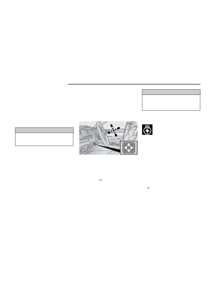
This feature allows you to tilt the steering column
upward or downward. It also allows you to lengthen or
shorten the steering column. The power tilt/telescoping
steering column control is located below the multifunc-
tion lever on the steering column.

Use the four-way control to adjust the steering column.

NOTE:

For vehicles equipped with Driver Memory Settings, use
the key fob or the memory switch on the driver's door
trim panel to return the tilt/telescopic steering column
to saved positions

page 52.

WARNING!

Do not adjust the steering column while driving.
Adjusting the steering column while driving or driving
with the steering column unlocked, could cause the
driver to lose control of the vehicle. Failure to follow
this warning may result in serious injury or death.

HEATED STEERING WHEEL —
IF EQUIPPED

The steering wheel contains a heating ele-
ment that helps warm your hands in cold
weather. The heated steering wheel has only
one temperature setting. Once the heated

steering wheel has been turned on, it will stay on until
the operator turns it off. The heated steering wheel may
not turn on when it is already warm.

The heated steering wheel button is located within the
Uconnect system and, if equipped, on the instrument
panel below the radio. You can access the button
through the Climate or Controls menu of the
touchscreen.

Press the heated steering wheel button once to turn
the heating element on.

Press the heated steering wheel button a second
time to turn the heating element off.

NOTE:

The engine must be running for the heated steering
wheel to operate.

For information on use with the Remote Start system,
see

page 41.

Power Tilt/Telescoping Steering Control Location

50

GETTING TO KNOW YOUR VEHICLE
WARNING!

Persons who are unable to feel pain to the skin
because of advanced age, chronic illness, diabe-
tes, spinal cord injury, medication, alcohol use,
exhaustion, or other physical conditions must exer-
cise care when using the steering wheel heater. It
may cause burns even at low temperatures, espe-
cially if used for long periods.

Do not place anything on the steering wheel that
insulates against heat, such as a blanket or steer-
ing wheel covers of any type and material. This
may cause the steering wheel heater to overheat.

UCONNECT VOICE RECOGNITION QUICK
TIPS — IF EQUIPPED

INTRODUCING VOICE
RECOGNITION

Start using Uconnect Voice Recognition with these help-
ful quick tips. These key Voice Commands and tips will
help you control your vehicle’s Voice Recognition (VR)
system.

BASIC VOICE COMMANDS

The following basic Voice Commands can be given at
any point while using your Uconnect system.

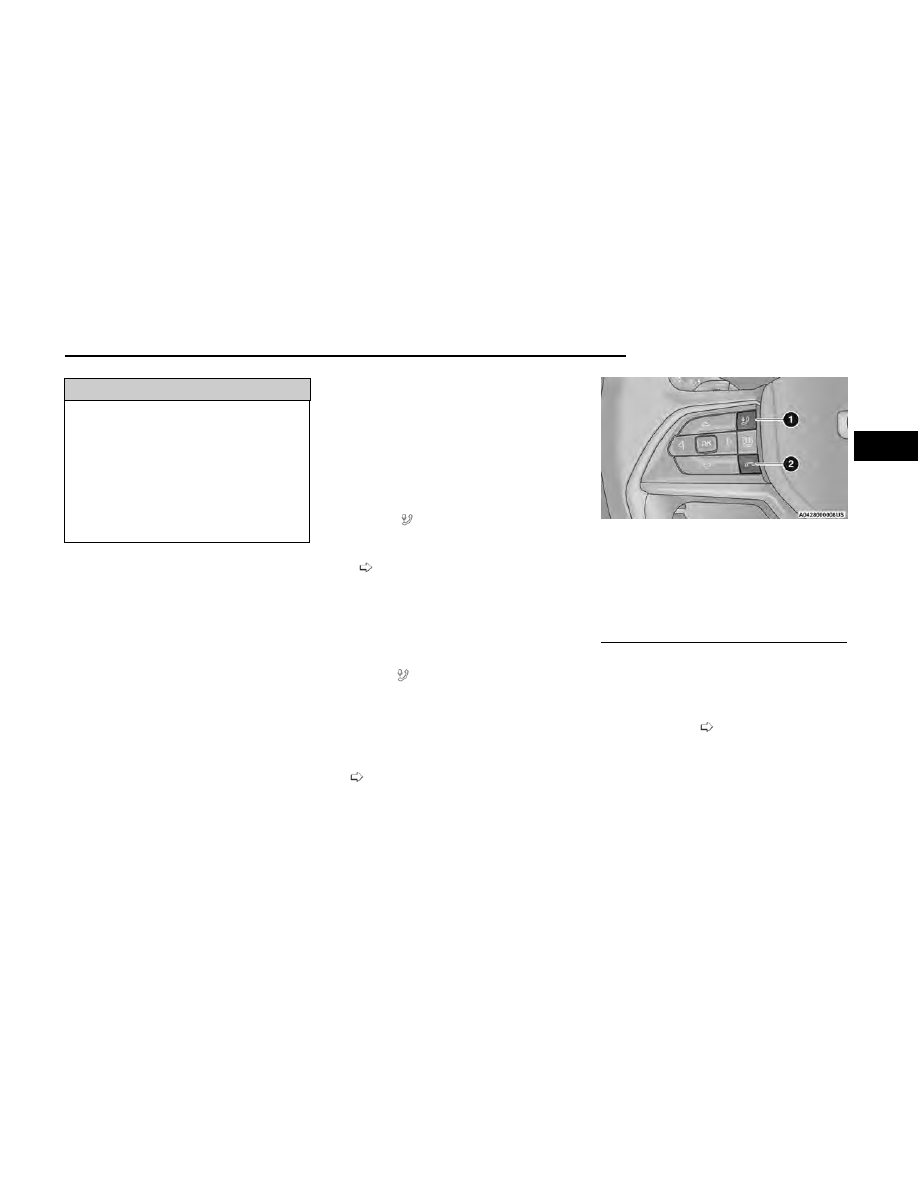
Push the VR button on the steering wheel or say the
vehicle’s Wake Up word, “Hey Uconnect” or “Hey
Jeep®”.

The factory default Wake Up word is set to “Hey
Uconnect” and can be reprogrammed through the
Uconnect Settings. After the beep, say:

Cancel

” to stop a current voice session.

Help

” to hear a list of suggested Voice Commands.

Repeat

” to listen to the system prompts again.

Notice the visual cues that inform you of your Voice
Recognition system’s status.

GET STARTED

The VR button

is used to activate/deactivate your

Voice Recognition system. You can also use the sys-
tem’s “Wake Up” word to activate voice recognition. The
“Wake Up” word can be set through the Uconnect Set-
tings

page 199.

Helpful hints for using Voice Recognition:

Reduce background noise. Wind noise and passen-
ger conversations are examples of noise that may
impact recognition.

Speak clearly at a normal pace and volume while
facing straight ahead.

Each time you give a Voice Command, first push the
VR button

or say the “Wake Up” word, wait until

after the beep, then say your Voice Command.

You can interrupt the help message or system
prompts by pushing the VR button and saying a
Voice Command from the current category.

You can also interrupt the help message or system
prompts by speaking. This feature is called “barge-
in” and can be set through the Uconnect Settings

page 199.

ADDITIONAL INFORMATION

© 2023 FCA US LLC. All rights reserved. Mopar and
Uconnect are registered trademarks and Mopar Owner
Connect is a trademark of FCA US LLC. SiriusXM® and
all related marks and logos are trademarks of
SiriusXM® Radio Inc.

page 383.

For Uconnect system support, call 1-877-855-8400
(24 hours a day 7 days a week) or visit
DriveUconnect.com (US) or DriveUconnect.ca (Canada).

Uconnect Voice Command Buttons

1 — For Vehicles Equipped With Navigation: Push The
Voice Recognition Button To Begin Radio, Media, Navi-
gation, Climate, Start Or Answer A Phone Call, And Send
Or Receive A Text
1 — For Vehicles Not Equipped With Navigation: Push
The Phone Button To Answer An Incoming Phone Call
2 — Push The Hang Up Button To End A Call Currently In
Progress

GETTING TO KNOW YOUR VEHICLE

51

2

DRIVER AND PASSENGER MEMORY
SETTINGS — IF EQUIPPED

This feature allows the driver, and if equipped, also the
front passenger to save up to two different memory
profiles for easy recall through a memory switch. Each
memory profile saves desired position settings for the
following features:

Driver’s Side

Seat position

Easy Entry/Exit seat (if equipped)

Side mirrors

Power tilt and telescopic steering column
(if equipped)

A set of desired radio station presets

Passenger’s Side (If Equipped)

Seat Position

The memory settings switches are located on the front
door panels, next to the door handle, and consists of
three buttons:

The set (S) button, which is used to activate the
memory save function.

The (1) and (2) buttons which are used to recall
either of two saved memory profiles.

NOTE:

Your vehicle is equipped with two key fobs, each can
be linked to either driver’s side memory position
1 or 2.

Front passenger memory settings cannot be linked
to a key fob.

PROGRAMMING THE MEMORY
FEATURE

To create a new memory profile, perform the following:

NOTE:

Saving a new memory profile will erase the selected
profile from memory.

1. Place the vehicle’s ignition in the ON/RUN position

(do not start the engine).

2. Adjust all memory profile settings to desired prefer-

ences (i.e., seat, side mirror, power tilt/telescopic
steering column and radio station presets).

3. Push and release the set (S) button on the memory

switch.

4. Within five seconds, push and release either of the

memory buttons (1) or (2). The instrument cluster
display will indicate which memory position has
been set.

NOTE:

Memory profiles can be set without the vehicle in PARK,
but the vehicle must be below 5 mph (8 km/h) to recall
a memory profile.

LINKING AND UNLINKING THE KEY
FOB TO MEMORY

Your key fobs can be programmed to recall one of two
saved driver’s side memory profiles.

NOTE:

Before programming your key fobs you must select the
“Personal Settings Linked To Key Fob” feature through
the Uconnect Settings

page 199.

To program your key fobs, perform the following:

1. Place the vehicle’s ignition in the OFF position.

2. Select a desired driver’s side memory profile, 1 or 2.

3. Once the profile has been recalled, push and

release the set (S) button on the memory switch.

4. Within five seconds, push and release button (1) or

(2) accordingly. “Memory Profile Set” (1 or 2) will
display in the instrument cluster.

5. Push and release the lock button on the key fob

within 10 seconds.

Memory Setting Buttons

52

GETTING TO KNOW YOUR VEHICLE

NOTE:

Your key fobs can be unlinked from your driver’s side
memory settings by pushing the set (S) button, and
within 10 seconds, pushing the unlock button on the
key fob.

MEMORY POSITION RECALL

NOTE:

Memory Recall is available when not in PARK, if the
vehicle speed is below 5 mph (8 km/h).

To recall a memory settings profile using the
memory switches, push memory button (1) or (2) on
the memory switch.

To recall the driver’s side memory settings using the
key fob, push the unlock button on the key fob
linked to memory position 1 or 2.

A recall can be canceled by pushing any of the memory
buttons during a recall (S, 1, or 2), or by pushing any of
the seat adjustment switches. When a recall is can-
celed, the seat and power tilt/telescopic steering col-
umn will stop moving. A delay of one second will occur
before another recall can be selected.

SEATS

Seats are a part of the Occupant Restraint system of
the vehicle.

WARNING!

It is dangerous to ride in a cargo area, inside or
outside of a vehicle. In a collision, people riding in
these areas are more likely to be seriously injured
or killed.

(Continued)

WARNING!

Do not allow people to ride in any area of your
vehicle that is not equipped with seats and seat
belts. In a collision, people riding in these areas
are more likely to be seriously injured or killed.

Be sure everyone in your vehicle is in a seat and
using a seat belt properly.

MANUAL ADJUSTMENT FRONT
SEATS — IF EQUIPPED

WARNING!

Adjusting a seat while the vehicle is moving is dan-
gerous. The sudden movement of the seat could
cause you to lose control. The seat belt might not
be adjusted properly and you could be injured.
Adjust the seat only while the vehicle is parked.

Do not ride with the seatback reclined so that the
shoulder belt is no longer resting against your
chest. In a collision you could slide under the seat
belt and be seriously or even fatally injured. Use
the recliner only when the vehicle is parked.

Manual Front Passenger Seat

Forward/Rearward Adjustment

Some models may be equipped with a manual front
passenger seat. The passenger seat can be adjusted
forward or rearward by using a bar located by the front
of the seat cushion, near the floor.

While sitting in the seat, lift up on the bar located under
the seat cushion and move the seat forward or rear-
ward. Release the bar once you have reached the
desired position. Then, using body pressure, move for-
ward and rearward on the seat to be sure that the seat
adjusters have latched.

WARNING!

Adjusting a seat while driving may be dangerous.
Moving a seat while driving could result in loss of
control which could cause a collision and serious
injury or death.

Seats should be adjusted before fastening the seat
belts and while the vehicle is parked. Serious
injury or death could result from a poorly adjusted
seat belt.

Adjustment Bar

GETTING TO KNOW YOUR VEHICLE

53

2

Manual Front Passenger Seatback

Adjustment — Recline

To recline, lean forward slightly and lift the lever located
on the outboard side of the seat. Then, push the seat
rearward to the desired position and release the lever.
To return the seatback to its normal position, lean for-
ward and lift the lever. To ensure the seatback is
latched, use body pressure to lean forward and
rearward.

WARNING!

Do not ride with the seatback reclined so that the
shoulder belt is no longer resting against your chest.
In a collision you could slide under the seat belt,
which could result in serious injury or death.

MANUAL ADJUSTMENT REAR
SEATS

Vehicles equipped with third row seating may have a
second row bench seat, or second row captain’s chairs.
Vehicles equipped with only second row seating, will
have a second row bench seat.

WARNING!

Do not place luggage or cargo higher than the top of
the seatback. This could impair visibility or become a
dangerous projectile in a sudden stop or collision.

NOTE:

You may experience deformation in the seat cushion
from the seat belt buckles if the seats are left folded for
an extended period of time. This is normal and by sim-
ply unfolding the seats to the open position, over time
the seat cushion will return to its normal shape.

Second Row Bench Seat — If Equipped

SECOND ROW BENCH SEAT FORWARD/
REARWARD ADJUSTMENT — IF EQUIPPED

Lift up on the adjusting bar located at the front of the
seat near the floor and release it when the seat is at
the desired position. Then, using body pressure, move
forward and rearward on the seat to be sure that the
seat adjusters have latched.

SECOND ROW BENCH SEAT RECLINE
ADJUSTMENT

To recline, lean forward slightly and lift the lever located
on the outboard side of the seat. Then, push the seat
rearward to the desired position and release the lever.
To return the seatback to its normal position, lean for-
ward and lift the lever. To ensure the seatback is
latched, use body pressure to lean forward and
rearward.

Recline Lever

Rear Seat Adjustment Bar

Rear Seat Recline Lever

54

GETTING TO KNOW YOUR VEHICLE

WARNING!

Do not ride with the seatback reclined so that the
shoulder belt is no longer resting against your chest.
In a collision you could slide under the seat belt,
which could result in serious injury or death.

SECOND ROW BENCH FOLD FLAT SEAT

To provide additional storage area, each rear seat can
be folded flat. This allows for extended cargo space and
still maintains some rear seating room.

NOTE:

Prior to folding the rear seat, it may be necessary to
position the front seat to its mid-track position. Also, be
sure that the front seats are fully upright and positioned
forward. This will allow the rear seat to fold down easily.

To lower the seatback, pull upward on the recline lever
located on the outboard side of the seat, and let the
seatback fold forward automatically.

To raise the seatback, fold the seatback up into its origi-
nal position and lock it into place.

WARNING!

Be certain that the seatback is securely locked into
position. If the seatback is not securely locked into
position the seat will not provide the proper stability
for child seats and/or passengers. An improperly
latched seat could cause serious injury.

SECOND ROW BENCH SEAT EASY ACCESS
FOR THIRD ROW — IF EQUIPPED

If the vehicle is equipped with third row seating, the
second row seats can tip forward to allow passengers to
easily access the third row seats.

Pull upward on the easy entry lever located on the out-
board side of the seatback, then tip and slide the entire
seat forward.

To return the seat to a sitting position, unfold the seat-
back upright until it locks and push the seat rearward
until the track locks.

Second Row Captain’s Chairs —

If Equipped

Vehicles equipped with third row seating may be
equipped with second row captain’s chairs.

SECOND ROW CAPTAIN’S CHAIRS
FORWARD/REARWARD ADJUSTMENT

Lift up on the adjusting bar located at the front of the
seat near the floor and release it when the seat is at
the desired position. Then, using body pressure, move
forward and rearward on the seat to be sure that the
seat adjusters have latched.

Second Row Bench Seat Folded Flat

Easy Entry Lever Location

Access To Third Row Seats

GETTING TO KNOW YOUR VEHICLE

55

2

SECOND ROW CAPTAIN’S CHAIRS RECLINE
ADJUSTMENT

To recline, lean forward slightly and lift the lever located
on the outboard side of the seat. Then, push the seat
rearward to the desired position and release the lever.
To return the seatback to its normal position, lean for-
ward and lift the lever. To ensure the seatback is
latched, use body pressure to lean forward and
rearward.

WARNING!

Do not ride with the seatback reclined so that the
shoulder belt is no longer resting against your chest.
In a collision you could slide under the seat belt,
which could result in serious injury or death.

SECOND ROW CAPTAIN’S CHAIRS FOLD FLAT
SEATS

The second row seatbacks can be folded flat to carry
cargo.

Pull upward on the recline lever located on the out-
board side of each second row seat, and guide the
seatback down into the folded position.

To Raise The Rear Seats

Fold the seatbacks upward to their original position,
and lock them into place.

WARNING!

Be certain that the seatback is securely locked into
position. If the seatback is not securely locked into
position the seat will not provide the proper stability
for child seats and/or passengers. An improperly
latched seat could cause serious injury.

SECOND ROW CAPTAIN’S CHAIR EASY
ACCESS FOR THIRD ROW

The second row seats can tip forward to allow passen-
gers to easily access the third row seats.

Pull upward on the easy entry lever located on the out-
board side of the seatback, then tip and slide the entire
seat forward.

Rear Seat Adjustment Bar

Rear Seat Recline Lever

Second Row Captain’s Chairs Folded Flat

Easy Entry Lever Location

56

GETTING TO KNOW YOUR VEHICLE

To return the seat to a sitting position, unfold the seat-
back upright until it locks and push the seat rearward
until the track locks.

Manual Folding Third Row — If Equipped

Both third row seats can be folded forward to increase
the cargo area. To lower either seat, pull on the release
handle located on the back of the seat and lower the
seat using the pull strap located next to the release
handle.

NOTE:

The second row seats must be in their full upright posi-
tion or folded flat when folding the third row seats.

To raise the seat, pull the seat toward you using the
strap located on the back of the seat.

WARNING!

Be certain that the seatback is securely locked into
position. If the seatback is not securely locked into
position the seat will not provide the proper stability
for child seats and/or passengers. An improperly
latched seat could cause serious injury.

POWER ADJUSTMENT FRONT
SEATS — IF EQUIPPED

Some models may be equipped with 12-way power
driver and front passenger seats. The power seat
switches are located on the outboard side of the seat.
There are three switches that control the movement of
the seat cushion and the seatback.

Access To Third Row Seats

Release Handles

Third Row Folded

Power Seat Switches

1 — Cushion Extender Switch (If Equipped)
2 — Seat Switch
3 — Seatback And Bolster Adjustment Switch

GETTING TO KNOW YOUR VEHICLE

57

2

Adjusting The Seat Forward Or

Rearward

The seat can be adjusted both forward and rearward.
Push the seat switch forward or rearward. The seat will
move in the direction of the switch. Release the switch
when the desired position has been reached.

Adjusting The Seat Up Or Down

The height of the seats can be adjusted up or down.
Pull upward or push downward on the rear of seat
switch, the seat will move in the direction of the switch.
Release the switch when the desired position has been
reached.

Tilting The Seat Up Or Down

The angle of the seat cushion can be adjusted in two
directions. Pull upward or push downward on the front
of the seat switch, the front of the seat cushion will
move in the direction of the switch. Release the switch
when the desired position has been reached.

Reclining The Seatback

The angle of the seatback can be adjusted forward or
rearward. Push the seatback switch forward or rear-
ward, the seat will move in the direction of the switch.
Release the switch when the desired position is
reached.

WARNING!

Adjusting a seat while driving may be dangerous.
Moving a seat while driving could result in loss of
control which could cause a collision and serious
injury or death.

Seats should be adjusted before fastening the seat
belts and while the vehicle is parked. Serious
injury or death could result from a poorly adjusted
seat belt.

Do not ride with the seatback reclined so that the
shoulder belt is no longer resting against your
chest. In a collision you could slide under the seat
belt, which could result in serious injury or death.

CAUTION!

Do not place any article under a power seat or
impede its ability to move as it may cause damage to
the seat controls. Seat travel may become limited if
movement is stopped by an obstruction in the seat's
path.

Seatback Bolster Adjustment —

If Equipped

The front driver and passenger seatback bolsters can
be extended outward, or retracted inward by pushing
the bolster adjustment button located in the center of
the seatback switch.

Push the top of the button to extend the bolsters, or
push the bottom of the button to retract the bolsters.

Cushion Extender

The cushion can be extended forward a few inches
(centimeters) to increase thigh support. Push the cush-
ion extender switch forward or rearward to extend or
retract the cushion. Release the switch when the
desired position has been reached.

Power Lumbar — If Equipped

Vehicles equipped with power driver or passenger seats
may also be equipped with power lumbar. The power
lumbar switch is located on the outboard side of the
power seat. Push the switch forward to increase the
lumbar support. Push the switch rearward to decrease
the lumbar support. Pushing upward or downward on
the switch will raise and lower the position of the
support.

Seatback Bolster Adjustment Button

1 — Extend Seatback Bolsters
2 — Retract Seatback Bolsters

58

GETTING TO KNOW YOUR VEHICLE

Easy Entry/Exit Seat — If Equipped

This feature provides automatic driver seat positioning
to enhance driver mobility when entering and exiting
the vehicle.

The distance the driver seat moves depends on where
you have the driver seat positioned when you place the
vehicle’s ignition in the OFF position.

When you place the vehicle’s ignition in the OFF
position, the driver seat will move about 2.4 inches
(6 cm) rearward if the driver seat position is greater
than or equal to 2.7 inches (6.8 cm) forward of the
rear stop. The seat will return to its previously set
position when you place the vehicle’s ignition in the
ON/RUN position.

The Easy Entry/Easy Exit feature is disabled when
the driver seat position is less than 0.9 of an inch
(2.3 cm) forward of the rear stop. At this position,
there is no benefit to the driver by moving the seat
for Easy Exit or Easy Entry.

When enabled in Uconnect Settings, Easy Entry and
Easy Exit positions are stored in each memory setting
profile

page 52.

NOTE:

The Easy Entry/Exit feature is enabled or disabled
within the Uconnect system

page 199.

POWER ADJUSTMENT REAR
SEATS — IF EQUIPPED

WARNING!

Adjusting a seat while driving may be dangerous.
Moving a seat while driving could result in loss of
control which could cause a collision and serious
injury or death.

Seats should be adjusted before fastening the seat
belts and while the vehicle is parked. Serious
injury or death could result from a poorly adjusted
seat belt.

Do not ride with the seatback reclined so that the
shoulder belt is no longer resting against your
chest. In a collision you could slide under the seat
belt, which could result in serious injury or death.

Do not place the seat belt webbing behind the
third row stow clip when using the seat belt to
restrain an occupant. The seat belt will not be posi-
tioned properly on the occupant and they could be
more seriously injured in an accident as a result.

CAUTION!

Do not place any article under a power seat or
impede its ability to move as it may cause damage to
the seat controls. Seat travel may become limited if
movement is stopped by an obstruction in the seat's
path.

Rear Seat Power Folding Seatbacks —

If Equipped

If the vehicle is equipped with third row seating, the
second and third rows may be equipped with power
folding seatbacks.

A one-touch power folding seat switch is located in the
right rear trim panel inside the cargo area, as part of a
switch bank.

NOTE:

You may need to move the front seats forward to
allow the second row seats to fold properly, as they
may bump into the Rear Seat Entertainment touch-
screens (if equipped).

The third row seat belts may interfere with the
power folding of the seat. Place the seat belt web-
bing behind the stow clip before stowing or opening
the seat. When the seat is in the desired position,
remove the webbing from the stow clip so that it is
ready for use. Never leave the seat belt in the stow
clip when it is used to restrain an occupant.

The head restraints will lower automatically as nec-
essary when the power seat begins to move when
the vehicle is in PARK, and a rear door or the liftgate
is open.

The rear switch bank allows multiple power folding posi-
tions for the second and third row seats. The second
row seats can be folded using these switches, while the
third row can be folded or unfolded.

Power Lumbar Switch

GETTING TO KNOW YOUR VEHICLE

59

2

There are also power folding switches for the third row
seats located on the C-pillar (just behind the rear doors
on the trim panels).

POWER SEATBACK MASSAGE —
IF EQUIPPED

The driver’s and front passenger’s seatbacks may be
equipped with power massage.

The massage feature can be turned on/off through the
massage button located on the door panel near the
handle, or through the Comfort screen on the radio.

Once activated by either method, the massage controls
will display on the radio screen, and “Massage Type”
and “Intensity Level” can be selected for the activated
seat.

There are four intensity levels and five massage types
that can be selected.

Intensity Levels:

High

Med

Low

Off

Massage Types:

Waterfall

Lower Back

Extend

Low Extend

Rock Climb

The selected settings will save in the system’s memory
when turned off, and will resume the next time the sys-
tem is turned on.

Rear Panel Power Switch Bank

1 — Second Row Left Side Fold
2 — Second Row Right Side Fold
3 — Third Row Left Side Fold/Unfold
4 — Third Row Right Side Fold/Unfold

C-Pillar Power Folding Switches (Left Side Shown)

1 — Third Row Left Side Fold/Unfold
2 — Third Row Right Side Fold/Unfold

Door Panel Massage Button

60

GETTING TO KNOW YOUR VEHICLE

NOTE:

The engine must be running for the power seatback
massage to operate.

The massage feature will turn off after 20 minutes
of use. However, if the massage type or intensity
level is changed, the timer then resets.

HEATED SEATS — IF EQUIPPED

WARNING!

Persons who are unable to feel pain to the skin
because of advanced age, chronic illness, diabe-
tes, spinal cord injury, medication, alcohol use,
exhaustion or other physical condition must exer-
cise care when using the seat heater. It may cause
burns even at low temperatures, especially if used
for long periods of time.

Do not place anything on the seat or seatback that
insulates against heat, such as a blanket or cush-
ion. This may cause the seat heater to overheat.
Sitting in a seat that has been overheated could
cause serious burns due to the increased surface
temperature of the seat.

Front Heated Seats

The front heated seats control buttons are
located on the center stack below the radio
screen or within the Uconnect system. You
can gain access to the control buttons

through the Comfort screen.

Press the heated seat switch once to turn the HI
setting on.

Press the heated seat switch a second time to turn
the MED setting on.

Press the heated seat switch a third time to turn the
LO setting on.

Press the heated seat switch a fourth time to turn
the heating elements off.

NOTE:

Once a heat setting is selected, heat will be felt
within two to five minutes.

The engine must be running for the heated seats to
operate.

The level of heat selected will stay on until the
operator changes it.

For information on use with the Remote Start system,
see

page 41.

Rear Heated Seats — If Equipped

The two second row outboard seats may be
equipped with heated seats. There are two
heated seat switches that allow the rear pas-
sengers to operate the seats independently.

The heated seat switches for each heater are located
on the rear of the center console.

You can choose from HI, MED, LO, or OFF heat settings.
Indicator lights in each switch illuminate indicating the
level of heat in use.

Push the heated seat switch once to turn the HI set-
ting on.

Push the heated seat switch a second time to turn
the MED setting on.

Push the heated seat switch a third time to turn the
LO setting on.

Push the heated seat switch a fourth time to turn
the heating elements off.

The level of heat selected will stay on until the operator
changes it.

NOTE:

The engine must be running for the heated seats to
operate.

VENTILATED SEATS — IF EQUIPPED

Located in the seat cushion and seatback are fans that
draw the air from the passenger compartment and
move air through fine perforations in the seat cover to
help keep the occupant cooler in higher ambient
temperatures.

Front Ventilated Seats

The ventilated seats control buttons are
located on the center stack below the radio
screen or within the Uconnect system. The
fans operate at three speeds: HI, MED and

LO.

Press the ventilated seat switch once to choose HI.

Press the ventilated seat switch a second time to
choose MED.

Press the ventilated seat switch a third time to
choose LO.

Press the ventilated seat switch a fourth time to
turn the ventilation off.

NOTE:

The engine must be running for the ventilated seats to
operate.

For information on use with the Remote Start system,
see

page 41.

GETTING TO KNOW YOUR VEHICLE

61

2

Rear Ventilated Seats — If Equipped

The two second row outboard seats may be
equipped with ventilated seats. The rear ven-
tilated seat control switches are located on
the rear of the center console and allow the

rear passengers to operate the seats independently.
The fans operate at three speeds: HI, MED, and LO.
Push the ventilated seat switches to toggle through the
speeds, or to turn the feature off.

There are two ventilated seat switches

Push the ventilated seat switch once to choose HI.

Push the ventilated seat switch a second time to
choose MED.

Push the ventilated seat switch a third time to
choose LO.

Push the ventilated seat switch a fourth time to turn
the ventilation off.

NOTE:

The engine must be running for the ventilated seats to
operate.

HEAD RESTRAINTS

Head restraints are designed to reduce the risk of injury
by restricting head movement in the event of a rear
impact. Head restraints should be adjusted so that the
top of the head restraint is located above the top of
your ear.

WARNING!

All occupants, including the driver, should not oper-
ate a vehicle or sit in a vehicle’s seat until the
head restraints are placed in their proper positions
in order to minimize the risk of neck injury in the
event of a crash.

(Continued)

WARNING!

Head restraints should never be adjusted while the
vehicle is in motion. Driving a vehicle with the head
restraints improperly adjusted or removed could
cause serious injury or death in the event of a
collision.

Front Head Restraints

Your vehicle is equipped with front four-way driver and
passenger head restraints.

To raise the head restraint, pull upward on the head
restraint. To lower the head restraint, push the adjust-
ment button, located at the base of the head restraint,
and push downward on the head restraint.

NOTE:

The head restraints should only be removed by quali-
fied technicians, for service purposes only. If either of
the head restraints require removal, see an authorized
dealer.

To adjust the head restraint forward, pull the top of the
head restraint toward the front of the vehicle as desired
and release. To adjust the head restraint rearward, pull
the top of the head restraint to the forward most posi-
tion and release. The head restraint will return to the
rear most position.

Head Restraint Adjustment Button

Upright Position

Forward Adjustment

62

GETTING TO KNOW YOUR VEHICLE

WARNING!

All occupants, including the driver, should not oper-
ate a vehicle or sit in a vehicle’s seat until the
head restraints are placed in their proper positions
in order to minimize the risk of neck injury in the
event of a crash.

Head restraints should never be adjusted while the
vehicle is in motion. Driving a vehicle with the head
restraints improperly adjusted or removed could
cause serious injury or death in the event of a
collision.

Head Restraints — Second Row

Captain’s Chairs (If Equipped)

If the second row is equipped with captain’s chairs, the
head restraints are not adjustable or removable. They
automatically fold forward when the seatback is folded,
and do not return to their normal position when the
seatback is raised. After returning the seatback to its
upright position after a folding operation, raise the
head restraint until it locks in place.

WARNING!

All occupants, including the driver, should not oper-
ate a vehicle or sit in a vehicle’s seat until the
head restraints are placed in their proper positions
in order to minimize the risk of neck injury in the
event of a crash.

(Continued)

WARNING!

Head restraints should never be adjusted while the
vehicle is in motion. Driving a vehicle with the head
restraints improperly adjusted or removed could
cause serious injury or death in the event of a
collision.

Head Restraints — Second Row Bench

(If Equipped)

If the second row is equipped with a bench seat, the
head restraints on the outboard seats are not adjust-
able or removable. They automatically fold forward
when the seatback is folded, and do not return to their
normal position when the seatback is raised. After
returning the seatback to its upright position after a
folding operation, raise the head restraint until it locks
in place.

The center head restraint has one adjustment position,
and can be adjusted up or down when the seat is occu-
pied. Pull up on the head restraint to raise it. To lower
the head restraint, push the adjustment button located
on the base of the head restraint, and push downward
on the head restraint until it locks into place.

NOTE:

The center head restraint is not removable.

NOTE:

For information on child restraint tethering, see

page 252.

WARNING!

All occupants, including the driver, should not oper-
ate a vehicle or sit in a vehicle’s seat until the
head restraints are placed in their proper positions
in order to minimize the risk of neck injury in the
event of a crash.

Head restraints should never be adjusted while the
vehicle is in motion. Driving a vehicle with the head
restraints improperly adjusted or removed could
cause serious injury or death in the event of a
collision.

Center Seat Head Restraint Adjustment Button

GETTING TO KNOW YOUR VEHICLE

63

2

Third Row Head Restraints —

If Equipped

The third row head restraints are not adjustable or
removable, but can be folded for improved visibility
when the vehicle is in REVERSE, and there are no occu-
pants in the seats.

Press the Headrest Fold button within the
Controls menu of the Uconnect system to
power fold the third row head restraints.

The head restraints will also automatically

fold when the seatbacks are folded forward using the
release handles on the backs of the seats from the
cargo area.

NOTE:

The head restraints must be raised manually when
occupying the third row.

Do not fold if there are passengers seated in the
third row seats.

WARNING!

All occupants, including the driver, should not oper-
ate a vehicle or sit in a vehicle’s seat until the
head restraints are placed in their proper positions
in order to minimize the risk of neck injury in the
event of a crash.

Head restraints should never be adjusted while the
vehicle is in motion. Driving a vehicle with the head
restraints improperly adjusted or removed could
cause serious injury or death in the event of a
collision.

MIRRORS

INSIDE REARVIEW MIRROR

Manual Mirror — If Equipped

The mirror head can be adjusted up, down, left, and
right. The mirror should be adjusted to center on the
view through the rear window.

Headlight glare from vehicles behind you can be
reduced by moving the small control under the mirror to
the night position (toward the rear of the vehicle). The
mirror should be adjusted while set in the day position
(small control forward toward the windshield).

Automatic Dimming Mirror —

If Equipped

The mirror head can be adjusted up, down, left, and
right. The mirror should be adjusted to center on the
view through the rear window.

This mirror automatically adjusts for headlight glare
from vehicles behind you.

NOTE:

The Automatic Dimming Mirror feature is disabled when
the vehicle is in REVERSE to improve the driver’s view.

You can turn the feature on or off through the Uconnect
system

page 199.

Digital Rearview Mirror — If Equipped

The Digital Rearview Mirror provides a high definition,
wide and unobstructed view of the road behind while
driving.

Position the mirror in the regular Automatic Dimming
Mirror mode, then activate the Digital Rearview Mirror
mode.

To activate the Digital Rearview Mirror, pull the on/off
control lever on the bottom of the mirror rearward
toward the driver.

Adjusting Rearview Mirror

Automatic Dimming Mirror

64

GETTING TO KNOW YOUR VEHICLE

Push the menu button next to the on/off control/toggle
to access the following mirror options:

Brightness

Tilt

Use the menu button to scroll through the feature
options, and the left and right scroll buttons to adjust
the feature content (brightness or tilt) higher/lower or
up/down.

When not in use, push the on/off forward toward the
windshield to return the mirror to the regular Automatic
Dimming Mirror.

NOTE:

The Digital Rearview Mirror is not as effective during
nighttime driving in low light applications due to low
ambient light levels. In the event that it provides the
user with less than expected vision, the mirror can
be reverted to a normal reflective electrochromatic
mirror by pushing the control/toggle forward in the
vehicle and putting the mirror into Automatic Dim-
ming Mirror mode.

When the rear window washer is activated by push-
ing the windshield wiper/washer lever forward, the
Rear Back Up and Digital Rearview Mirror
(if equipped) cameras are also washed. For more
information, see

page 77.

ILLUMINATED VANITY MIRRORS

To access an illuminated vanity mirror, flip down one of
the visors.

Lift the cover to reveal the mirror. The light will turn on
automatically.

Sun Visor Slide-On-Rod Feature —

If Equipped

The sun visor Slide-On-Rod feature allows for additional
flexibility in positioning the sun visor to block out the
sun.

1. Fold down the sun visor.

2. Unclip the visor from the center clip.

3. Pivot the sun visor toward the side window.

4. Extend the sun visor blade for additional sun

blockage.

NOTE:

The sun visor blade can also be extended while the sun
visor is against the windshield for additional sun block-
age through the front of the vehicle.

OUTSIDE MIRRORS

To receive maximum benefit, adjust the outside mir-
ror(s) to center on the adjacent lane of traffic with a
slight overlap of the view obtained on the inside mirror.

WARNING!

Vehicles and other objects seen in an outside convex
mirror will look smaller and farther away than they
really are. Relying too much on side convex mirrors
could cause you to collide with another vehicle or
other object. Use your inside mirror when judging the
size or distance of a vehicle seen in a side convex
mirror.

Digital Rearview Mirror

1 — On/Off Control/Toggle
2 — Menu Button
3 — Left Scroll Button
4 — Right Scroll Button

Lift Cover On Vanity Mirror

GETTING TO KNOW YOUR VEHICLE

65

2

Outside Mirrors Folding Feature

All outside mirrors are hinged and may be moved either
forward or rearward to resist damage. The hinges have
three detent positions:

Full forward position

Full rearward position

Normal position

Outside Mirrors With Turn Signal And

Approach Lighting — If Equipped

Driver and passenger outside mirrors with turn signal
and approach lighting contain four LEDs, which are
located in the upper outer corner of each mirror.

Three of the LEDs are turn signal indicators, which flash
with the corresponding turn signal lights in the front
and rear of the vehicle. Turning on the Hazard Warning
flashers will also activate these LEDs.

NOTE:

The approach lighting will not function when the gear
selector is moved out of the PARK position.

OUTSIDE AUTOMATIC DIMMING
MIRROR — IF EQUIPPED

The outside driver side mirror will automatically adjust
for glare from vehicles behind you. This feature is con-
trolled by the inside automatic dimming mirror. The mir-
ror will automatically adjust for headlight glare when
the inside mirror adjusts.

POWER MIRRORS

The power mirror control switch is located on the driv-
er's side door trim panel.

To adjust a mirror, rotate the control switch to the mirror
you want to adjust (L) or (R). Then push the switch in
the direction that you want the mirror to move.

NOTE:

Once adjustment is complete, rotate the knob to the
neutral position to prevent accidental movements.

Power Folding — If Equipped

To fold the door mirrors in using the Power Folding Mir-
ror function, rotate the control switch to the power fold-
ing position. Rotating the control to the left, right, or
neutral position will return the mirrors to the driving
position.

If the power mirror control switch is moved again during
door mirror folding (from closed to open position and
vice versa), the movement direction is reversed.

Resetting The Power Folding Outside Mirrors

You may need to reset the power folding mirrors if the
following occurs:

The mirrors are accidentally blocked while folding.

The mirrors are accidentally manually folded/
unfolded (by hand or by pushing the power folding
mirror switch).

The mirrors come out of the unfolded position.

The mirrors shake and vibrate at normal driving
speeds.

To reset the power folding mirrors: Fold and unfold
them by turning the switch (this may require multiple
switch activations to synchronize the driver and passen-
ger mirror). This resets them to their normal position.

Power mirror position can be saved as part of the Driver
Memory Settings (if equipped)

page 52.

AUTOMATIC POWER FOLDING
MIRRORS — IF EQUIPPED

When enabled within Uconnect Settings

page 199,

the exterior mirrors will automatically fold when the
vehicle’s ignition is placed in the OFF position, and after
the doors are locked and closed.

Power Mirror Switch

1 — Neutral Position
2 — Left Mirror
3 — Control Switch
4 — Right Mirror
5 — Power Folding Position

66

GETTING TO KNOW YOUR VEHICLE

The exterior mirrors will auto-fold in the following situa-
tions after the ignition is placed in the OFF position:

Pushing the lock button on the door panel before
the door is opened.

NOTE:

If the doors are already locked, push the lock button
again.

Opening the door, then pushing the lock button on
the door panel, followed by closing the door.

After exiting the vehicle, close the doors then push
the lock button on the key fob.

After exiting the vehicle, close the doors then touch
the lock icon on the Passive Entry door handle.

If the exterior mirrors were folded automatically, they
will unfold when the ignition is placed in the ON/RUN
position.

NOTE:

If the mirrors were folded manually (pushing the mirror
head inward by hand), OR by using the power folding
mirror switch on the driver’s door panel, they will not
automatically unfold.

HEATED MIRRORS — IF EQUIPPED

These mirrors are heated to melt frost or ice.
This feature will be activated whenever you
turn on the rear window defroster
(if equipped)

page 77.

TILT SIDE MIRRORS IN REVERSE —
IF EQUIPPED

Tilt Side Mirrors In Reverse provides automatic outside
mirror positioning which will aid the driver’s view of the
ground rearward of the front doors. Outside mirrors will
move slightly downward from the present position when
the vehicle is shifted into REVERSE. Outside mirrors will
then return to the original position when the vehicle is
shifted out of REVERSE position. Each stored memory
setting will have an associated Tilt Side Mirrors In
Reverse position.

NOTE:

The Tilt Side Mirrors In Reverse feature can be turned
on and off using the Uconnect system

page 199.

UNIVERSAL GARAGE DOOR OPENER
(HOMELINK®) — IF EQUIPPED

Use this QR code to access your digital
experience.

HomeLink® replaces up to three
hand-held transmitters that operate
devices such as garage door open-
ers, motorized gates, lighting or
home security systems. The HomeLink® unit is pow-
ered by your vehicle’s 12 Volt battery.

The HomeLink® buttons that are located in the
overhead console or sun visor designate the three
different HomeLink® channels.

To operate HomeLink®, push and release any of the
programmed HomeLink® buttons. These buttons
will activate the devices they are programmed to
with each press of the corresponding HomeLink®
button.

The HomeLink® indicator light is located above the
center button.

NOTE:

HomeLink® is disabled when the Vehicle Security sys-
tem is active

page 383.

BEFORE YOU BEGIN
PROGRAMMING HOMELINK®

For efficient programming and accurate transmission of
the Radio Frequency (RF) signal, it is recommended
that a new battery be placed in the hand-held transmit-
ter of the device that is being programmed to the
HomeLink® system. Make sure your hand-held trans-
mitter is programmed to activate the device you are
trying to program your HomeLink® button to.

Ensure that your vehicle is parked outside of the garage
before you begin programming.

HomeLink® Buttons And Indicator Light

Scan me

GETTING TO KNOW YOUR VEHICLE

67

2

It is recommended that you erase all the channels of
your HomeLink® before you use it for the first time.

ERASING ALL THE HOMELINK®
CHANNELS

To erase the channels, follow this procedure:

1. Place the ignition switch into the ON/RUN position.

2. Push and hold the two outside HomeLink® buttons

(I and III) for up to 20 seconds, or until the
HomeLink® indicator light flashes.

NOTE:

Erasing all channels should only be performed when
programming HomeLink® for the first time. Do not
erase channels when programming additional buttons.

IDENTIFYING WHETHER YOU HAVE
A ROLLING CODE OR NON-ROLLING
CODE DEVICE

Before programming a device to one of your
HomeLink® buttons, you must determine whether the
device has a rolling code or non-rolling code.

Rolling Code Devices

To determine if your device has a rolling code, a good
indicator is its manufacturing date. Typically, devices
manufactured after 1995 have rolling codes. A device
with a rolling code will also have a “LEARN” or “TRAIN”
button located where the antenna is attached to the
device. The button may not be immediately visible when
looking at the device. The name and color of the button
may vary slightly by manufacturer.

NOTE:

The “LEARN” or “TRAIN” button is not the button you
normally use to operate the device.

Non-rolling Code Devices

Most devices manufactured before 1995 will not have a
rolling code. These devices will also not have a “LEARN”
or “TRAIN” button.

PROGRAMMING HOMELINK® TO A
GARAGE DOOR OPENER

To program any of the HomeLink® buttons to activate
your garage door opener motor, proceed as follows:

NOTE:

All HomeLink® buttons are programmed using this pro-
cedure. You do not need to erase all channels when
programming additional buttons.

1. Place the ignition switch into the ON/RUN position.

2. Place the garage door opener transmitter 1 to

3 inches (3 to 8 cm) away from the HomeLink® but-
ton you wish to program, while keeping the
HomeLink® indicator light in view.

3. Push and hold the HomeLink® button you want to

program while you push and hold the garage door
opener transmitter button you are trying to replicate.

4. Continue to hold both buttons and observe the

HomeLink® indicator light. The HomeLink® indica-
tor light will flash slowly and then rapidly. Once this
happens, release both buttons.

NOTE:

Make sure the garage door opener motor is plugged in
before moving on to the rolling code/non-rolling code
final steps.

Rolling Code Garage Door Opener Final Steps

NOTE:

You have 30 seconds in which to initiate rolling code
final step 2, after completing rolling code final step 1.

1. At the garage door opener motor (in the garage),

locate the “LEARN” or “TRAIN” button. This can usu-
ally be found where the hanging antenna wire is
attached to the garage door opener motor. Firmly
push and release the “LEARN” or “TRAIN” button.

2. Return to the vehicle and push the programmed

HomeLink® button three times (holding the button
for two seconds each time). If the garage door
opener motor operates, programming is complete.

3. Push the programmed HomeLink® button to con-

firm that the garage door opener motor operates. If
the garage door opener motor does not operate,
repeat the final steps for the rolling code procedure.

Non-Rolling Code Garage Door Opener Final Steps

1. Push and hold the programmed HomeLink® button

and observe the HomeLink® indicator light. If the
HomeLink® indicator light stays on constantly, pro-
gramming is complete.

2. Push the programmed HomeLink® button to con-

firm that the garage door opener motor operates. If
the garage door opener motor does not operate,
repeat the steps from the beginning.

WARNING!

Your motorized door or gate will open and close
while you are programming the universal transmit-
ter. Do not program the transmitter if people or
pets are in the path of the door or gate.

(Continued)

68

GETTING TO KNOW YOUR VEHICLE

WARNING!

Do not run your vehicle in a closed garage or con-
fined area while programming the transmitter.
Exhaust gas from your vehicle contains carbon
monoxide which is odorless and colorless. Carbon
monoxide is poisonous when inhaled and can
cause you and others to be severely injured or
killed.

PROGRAMMING HOMELINK® TO A
MISCELLANEOUS DEVICE

The procedure on how to program HomeLink® to a mis-
cellaneous device follows the same procedure as pro-
gramming to a garage door opener

page 68. Be

sure to determine if the device has a rolling code, or
non-rolling code before beginning the programming
process.

NOTE:

Canadian Radio Frequency (RF) laws require transmit-
ter signals to time-out (or quit) after several seconds of
transmission, which may not be long enough for
HomeLink® to pick up the signal during programming.
Similar to this Canadian law, some U.S. gate operators
are designed to time-out in the same manner. The pro-
cedure may need to be performed multiple times to
successfully pair the device to your HomeLink®
buttons.

REPROGRAMMING A SINGLE
HOMELINK® BUTTON

To reprogram a single HomeLink® button that has been
previously trained, without erasing all the channels,
proceed as follows. Be sure to determine whether the
new device you want to program the HomeLink® button
to has a rolling code, or non-rolling code.

1. Place the ignition to the ON/RUN position, without

starting the engine.

2. Push and hold the desired HomeLink® button until

the HomeLink® indicator light begins to flash after
20 seconds.

Do not release the button.

3.

Without releasing the button

, proceed with Step

2 in “Programming HomeLink® To A Garage Door
Opener” and follow all remaining steps.

CANADIAN/GATE OPERATOR
PROGRAMMING

For programming transmitters in Canada/United States
that require the transmitter signals to “time-out” after
several seconds of transmission:

Canadian Radio Frequency (RF) laws require transmit-
ter signals to time-out (or quit) after several seconds of
transmission, which may not be long enough for
HomeLink® to pick up the signal during programming.
Similar to this Canadian law, some U.S. gate operators
are designed to time-out in the same manner.

It may be helpful to unplug the device during the cycling
process to prevent possible overheating of the garage
door or gate motor.

1. Place the ignition in the ON/RUN position.

NOTE:

For vehicles equipped with Keyless Enter ‘n Go™,
place the ignition in the ON/RUN position. Make
sure while programming HomeLink® with the
engine on that your vehicle is outside of your
garage, or that the garage door remains open at all
times.

2. Place the hand-held transmitter 1 to 3 inches (3 to

8 cm) away from the HomeLink® button you wish to
program while keeping the HomeLink® indicator
light in view.

3. Continue to push and hold the HomeLink® button

while you push and release (cycle) your hand-held
transmitter every two seconds until HomeLink® has
successfully accepted the frequency signal. The indi-
cator light will flash slowly and then rapidly when
fully trained.

4. Watch for the HomeLink® indicator to change flash

rates. When it changes, it is programmed. It may
take up to 30 seconds or longer in rare cases. The
garage door may open and close while you are
programming.

5. Push and hold the programmed HomeLink® button

and observe the indicator light.

NOTE:

If the indicator light stays on constantly, program-
ming is complete and the garage door/device
should activate when the HomeLink® button is
pushed.

To program the two remaining HomeLink® but-
tons, repeat each step for each remaining but-
ton. DO NOT erase the channels.

If you unplugged the garage door opener/device for
programming, plug it back in at this time.

GETTING TO KNOW YOUR VEHICLE

69

2

Reprogramming A Single HomeLink® Button
(Canadian/Gate Operator)

To reprogram a channel that has been previously
trained, follow these steps:

1. Place the ignition in the ON/RUN position.

2. Press and hold the desired HomeLink® button until

the indicator light begins to flash after 20 seconds.
Do not release the button.

3. Without releasing the button, proceed with

“Canadian/Gate Operator Programming” Step 2 and
follow all remaining steps.

SECURITY

It is advised to erase all channels before you sell or turn
in your vehicle.

To do this, push and hold the two outside buttons for
20 seconds until the indicator flashes. Note that all
channels will be erased. Individual channels cannot be
erased.

The HomeLink® Universal Transceiver is disabled when
the Vehicle Security system is active.

TROUBLESHOOTING TIPS

If you are having trouble programming HomeLink®,
here are some of the most common solutions:

Replace the battery in the garage door opener hand-
held transmitter.

Push the LEARN button on the garage door opener
to complete the training for a rolling code.

Did you unplug the device for programming and
remember to plug it back in?

If you have any problems, or require assistance, please
call toll-free 1-800-355-3515 or visit HomeLink.com for
information or assistance.

WARNING!

Vehicle exhaust contains carbon monoxide, a dan-
gerous gas. Do not run your vehicle in the garage
while programming the transmitter. Exhaust gas
can cause serious injury or death.

Your motorized door or gate will open and close
while you are programming the universal transmit-
ter. Do not program the transmitter if people, pets
or other objects are in the path of the door or gate.
Only use this transmitter with a garage door
opener that has a “stop and reverse” feature as
required by Federal safety standards. This includes
most garage door opener models manufactured
after 1982. Do not use a garage door opener with-
out these safety features.

EXTERIOR LIGHTS

HEADLIGHT SWITCH

The headlight switch is located on the left side of the
instrument panel, next to the steering wheel. The head-
light switch controls the operation of the headlights,
parking lights, instrument panel lights, and fog lights
(if equipped).

Headlight Switch

1 — Rotate Headlight Control
2 — Push Front Fog Light Control
3 — Ambient Light Dimmer Control
4 — Instrument Panel Dimmer Control

Headlight Switch (Vehicles Sold In Canada Only)

1 — Rotate Headlight Control
2 — Push Front Fog Light Control
3 — Ambient Light Dimmer Control
4 — Instrument Panel Dimmer Control

70

GETTING TO KNOW YOUR VEHICLE

NOTE:

Vehicles sold in Canada are equipped with a headlight
switch with an AUTO and ON detent but without an OFF
detent. Headlights will be deactivated when the head-
light switch is placed in the parking lights position. How-
ever, the Daytime Running Lights (DRLs) will be acti-
vated along with the front and rear marker lights. The
DRLs may be deactivated when the parking brake is
engaged.

To turn on the headlights, rotate the headlight switch
clockwise. When the headlight switch is on, the parking
lights, taillights, license plate light and instrument panel
lights are also turned on. To turn off the headlights,
rotate the headlight switch back to the O (off) position.

For vehicles sold in Canada, rotate the headlight switch
clockwise from the parking lights and instrument panel
lights position to the AUTO position for automatic head-
lights. Rotate to the second detent to turn on head-
lights, parking lights, and instrument panel lights
operation.

NOTE:

Your vehicle is equipped with plastic headlight and
fog light (if equipped) lenses that are lighter and
less susceptible to stone breakage than glass lights.
Plastic is not as scratch resistant as glass and
therefore different lens cleaning procedures must
be followed.

To minimize the possibility of scratching the lenses
and reducing light output, avoid wiping with a dry
cloth. To remove road dirt, wash with a mild soap
solution followed by rinsing.

CAUTION!

Do not use abrasive cleaning components, solvents,
steel wool or other abrasive materials to clean the
lenses.

MULTIFUNCTION LEVER

The multifunction lever is located on the left side of the
steering column.

DAYTIME RUNNING LIGHTS
(DRLS) — IF EQUIPPED

The Daytime Running Lights (DRLs) come on whenever
the engine is running, and the low beams are not on.
The lights will remain on until the ignition is placed in
the OFF or ON/RUN position, or the parking brake is
engaged. The low beams must be used for normal
nighttime driving.

NOTE:

For vehicles sold in Canada, the Daytime Running
Lights will automatically deactivate when the front
fog lights are turned on.

If allowed by law in the country in which the vehicle
was purchased the Daytime Running Lights can be
turned on and off using the Uconnect system

page 199.

On some vehicles, the Daytime Running Lights may
deactivate, or reduce intensity, on one side of the
vehicle (when a turn signal is activated on that
side), or on both sides of the vehicle (when the haz-
ard warning lights are activated).

HIGH/LOW BEAM SWITCH

Push the multifunction lever toward the instrument
panel to switch the headlights to high beams. Pulling
the multifunction back toward the steering wheel will
turn the low beams back on, or shut the high beams
off.

AUTOMATIC HIGH BEAMS —
IF EQUIPPED

The Automatic High Beam Headlight system provides
increased forward lighting at night by automating high
beam control through the use of a digital camera
mounted on the inside rearview mirror. This camera
detects vehicle specific light and automatically switches
from high beams to low beams until the approaching
vehicle is out of view.

NOTE:

The Automatic High Beam Headlight system can be
turned on or off by selecting or deselecting “Auto
Dim High Beams” within Uconnect Settings

page 199.

Multifunction Lever

GETTING TO KNOW YOUR VEHICLE

71

2

The headlight switch must also be turned to the
AUTO position after Automatic High Beams is
enabled within Uconnect Settings for the feature to
activate.

Automatic High Beams will only activate when the
vehicle speed is above 22 mph (35 km/h).

Broken, muddy, or obstructed headlights and tail-
lights of vehicles in the field of view will cause head-
lights to remain on longer (closer to the vehicle).
Also, dirt, film, and other obstructions on the wind-
shield or camera lens will cause the system to func-
tion improperly.

If the windshield or Automatic High Beam Headlight
Control mirror is replaced, the mirror must be re-aimed
to ensure proper performance. See a local authorized
dealer.

FLASH-TO-PASS

You can signal another vehicle with your headlights by
lightly pulling the multifunction lever toward you. This
will cause the high beam headlights to turn on, and
remain on, until the lever is released.

AUTOMATIC HEADLIGHTS

This system automatically turns the headlights on or off
according to ambient light levels. To turn the system on,
rotate the headlight switch counterclockwise to the
AUTO position. When the system is on, the headlight
time delay feature is also on. This means the headlights
will stay on for up to 90 seconds after you place the
ignition into the OFF position. The headlight time delay
can be programmed to 0/30/60/90 seconds within the
Uconnect system

page 199.

To turn the automatic system off, move the headlight
switch out of the AUTO position.

NOTE:

The engine must be running before the headlights will
come on in the automatic mode.

PARKING LIGHTS AND PANEL
LIGHTS

To turn on the parking lights and instrument panel
lights, rotate the headlight switch clockwise. To turn off
the parking lights, rotate the headlight switch back to
the O (off) position.

NOTE:

Vehicles sold in Canada are equipped with a headlight
switch with an AUTO and ON detent but without an OFF
detent. Headlights will be deactivated when the head-
light switch is placed in the parking lights position. How-
ever, the Daytime Running Lights (DRLs) will be acti-
vated along with the front and rear marker lights. The
DRLs may be deactivated when the parking brake is
engaged.

HEADLIGHTS ON AUTOMATICALLY
WITH WIPERS

If your vehicle is equipped with Automatic Headlights, it
also has this customer-programmable feature. When
your headlights are in the automatic mode and the
engine is running, they will automatically turn on when
the wiper system is on. This feature is programmable
through the Uconnect system

page 199.

NOTE:

When your headlights come on during the daytime, the
vehicle will monitor outside brightness and decide if the
instrument panel needs to be dimmed

page 74.

HEADLIGHT ILLUMINATION ON
APPROACH

When enabled, the headlights, exterior door handle
pocket lights (if equipped), and interior lights will illumi-
nate when the unlock button on the key fob is pushed
as the operator is approaching the vehicle. This feature
can be turned on/off, and the length of time the head-
lights stay on can be programmed for up to 90 seconds
within Uconnect Settings

page 199.

Proximity Wake-Up — If Equipped

This feature is enabled/disabled within the Uconnect
system, and is activated when the operator approaches
the driver’s door, passenger’s door, or liftgate with a
valid key fob on their person. Some exterior and interior
lights will illuminate in order to provide an increased
sense of welcome and security as the operator
approaches the vehicle in the dark. “Headlight Illumina-
tion On Approach” must be selected and set to a time
value other than zero within Uconnect Settings for Prox-
imity Wake-Up to activate.

The doors may be locked or unlocked for this feature to
activate, as long as the ignition is in the OFF position, or
during a Remote Start event. It will not activate if the
doors are locked and the ignition was placed in the
ON/RUN position.

NOTE:

Proximity Wake-Up may not activate under the following
conditions:

After numerous consecutive activations, in order to
conserve the vehicle’s battery

After the vehicle’s engine has been off for several
days

72

GETTING TO KNOW YOUR VEHICLE

Headlight Animation — If Equipped

When “Headlight Illumination On Approach” is turned
on, and set to a time value above zero, the exterior
lights illuminate in a theatrical manner during approach
to the vehicle. This feature is activated in the following
situations:

Proximity Wake-Up (if equipped) is activated

Remote Start is activated

The unlock button on the key fob is pushed

NOTE:

For Headlight Animation to activate with Remote Start
or with the push of the unlock button, “Greeting Lights”
must also be selected within the Uconnect system.

HEADLIGHT DELAY

To aid in your exit, your vehicle is equipped with a head-
light delay that will leave the headlights on for approxi-
mately 90 seconds. This delay is initiated when the igni-
tion is placed in the OFF position while the headlight
switch is on, and then the headlight switch is cycled off.
Headlight delay can be canceled by either turning the
headlight switch on then off, or by placing the ignition in
the ON/RUN position.

NOTE:

The headlight delay time is programmable through
Uconnect Settings

page 199.

LIGHTS-ON REMINDER

If the headlights or parking lights are left on after the
ignition is placed in the OFF position, a chime will
sound when the driver’s door is opened.

FRONT FOG LIGHTS — IF EQUIPPED

To activate the front fog lights, turn on the parking lights
or the low beam headlights, and push the fog light but-
ton on the headlight switch.

The fog lights will operate only when the parking lights
are on, or when the vehicle headlights are on low beam.
An indicator light located in the instrument cluster dis-
play will illuminate when the fog lights are on. The fog

lights will turn off when the button is pushed a second
time, when the headlight switch is rotated to the off
position, or the high beam is selected.

Cornering Lights

The cornering lights are a feature to improve visibility at
night while turning the vehicle. When activated, a light
incorporated in the front fog light will illuminate on the
side of the vehicle the steering wheel is rotated or the
turn signal indicator is on. It can be activated through
the Uconnect system

page 199.

TURN SIGNALS

Move the multifunction lever up or down and the arrows
on each side of the instrument cluster will flash to show
proper operation of the front and rear turn signal lights.

NOTE:

If either light remains on and does not flash, or there is
a very fast cluster turn indicator flash rate, check for a
defective outside light bulb.

LANE CHANGE ASSIST —
IF EQUIPPED

Tap the multifunction lever up or down once, without
moving beyond the detent, and the turn signal (right or
left) will flash three times then automatically turn off.

AUTOMATIC HEADLIGHT
LEVELING — IF EQUIPPED

This feature prevents the headlights from interfering
with the vision of oncoming drivers. Headlight leveling
automatically adjusts the height of the headlight beam
in reaction to changes in vehicle pitch.

Fog Light Button

Fog Light Button (Vehicles Sold In Canada Only)

GETTING TO KNOW YOUR VEHICLE

73

2

BATTERY SAVER

To protect the life of your vehicle’s battery, load shed-
ding is provided for both the interior and exterior lights.

If the ignition is placed in the OFF position and any door
is left ajar for 10 minutes or the overhead console
Dome On switch is left on for 10 minutes, the interior
lights will automatically turn off.

NOTE:

Battery saver mode is canceled if the ignition is in the
ON/RUN position.

If the headlights remain on while the ignition is placed
in the OFF position, the exterior lights will automatically
turn off after eight minutes. If the headlights are turned
on and left on for eight minutes while the ignition is in
the OFF position, the exterior lights will automatically
turn off.

INTERIOR LIGHTS

COURTESY LIGHTS

Courtesy and dome lights are turned on when the front
doors are opened or the Dome ON button is pushed on
the overhead console. If your vehicle is equipped with
Remote Keyless Entry and the unlock button is pushed
on the key fob, the courtesy and dome lights will turn
on. When a door is open and the interior lights are on,
pressing the Dome Defeat button on the overhead con-
sole will cause all of the interior lights to turn off.

Front Map/Reading Lights — If Equipped

The overhead console lights can also be operated indi-
vidually as reading lights by pushing the corresponding
buttons.

Rear Courtesy/Reading Lights

Located above the rear passenger seating in both sec-
ond and third rows, along the trim, are courtesy/
reading lights. The courtesy lights turn on when a door
or the liftgate is opened. The lights will also turn on
when the unlock button on the key fob is pushed.

The courtesy lights also function as reading lights. Push
the reading light button to turn these lights on while
inside the vehicle. Push the reading light button a sec-
ond time to turn each light off.

Dimmer Controls

The dimmer controls are inboard and adjacent to the
headlight switch located on the left side of the instru-
ment panel.

With the parking lights or headlights on, rotating the
right dimmer control upward will increase the bright-
ness of the instrument cluster lights. Rotating the left
dimmer control will adjust the interior light levels of the
ambient lighting on the instrument panel and doors.
Certain ambient lights may be color customizable

page 75.

Courtesy Lights

1 — Reading Light On/Off Buttons
2 — Dome Defeat Button
3 — Ambient Light
4 — Dome ON Button

Dimmer Controls

1 — Ambient Light Dimmer Control
2 — Instrument Panel Dimmer Control

74

GETTING TO KNOW YOUR VEHICLE

NOTE:

Multicolor ambient lighting for first and second
rows, and overhead white ambient lighting in the
second and third row (if equipped) seating areas,
may not be equipped in the vehicle.

Adjusting the right dimmer control all the way
upward will switch the radio screen to Light theme,
while moving the control all the way down will switch
the radio screen to the Dark theme.

The dimming of lighting linked to the headlight sta-
tus (i.e. radio screen brightness) is programmable
through the Uconnect system

page 199.

Multicolor Ambient Lighting —

If Equipped

The color of certain ambient lighting inside of the
vehicle can be selected within the Apps menu on the
radio screen, or within Uconnect Settings

page 199. Brightness is adjusted using the ambi-

ent light dimmer control on the headlight switch.

Five colors can be selected for the following two zones
inside of the vehicle:

Zone 1:

Instrument panel decorative ambient lights

Zone 2:

Front seat footwell areas below the instrument
panel

Lighting below the second row seats

Map pocket lighting on all four door panels

These areas can be set to different colors, or if the
SYNC button is selected within the settings menu, all
colored lights will be set to the same color
automatically.

NOTE:

All other ambient lighting inside of the vehicle will
remain white, and the ambient light dimmer control
switch will adjust all ambient lighting at the same time.

WINDSHIELD WIPERS AND WASHERS

The windshield wiper/washer lever is located on the
right side of the steering column. The front wipers are
operated by rotating a switch, located on the end of the
lever.

WINDSHIELD WIPER OPERATION

The wipers and washers are operated by a switch within
the wiper lever. Rotate the switch at the end of the lever
upward, to the first detent past the intermittent settings
for low-speed wiper operation. Rotate the switch at the
end of the lever upward to the second detent past the
intermittent settings for high-speed wiper operation. To
turn the windshield wipers off, rotate the switch within
the lever all the way down to OFF.

Dimmer Controls (Vehicles Sold In Canada Only)

1 — Ambient Light Dimmer Control
2 — Instrument Panel Dimmer Control

Multifunction Lever

1 — Pull For Front Washer
2 — Rotate For Rear Wiper Operation
3 — Rotate For Front Wiper Operation
4 — Push Forward For Rear Washer
5 — Push Up For Mist

GETTING TO KNOW YOUR VEHICLE

75

2

CAUTION!

Always remove any buildup of snow that prevents the
windshield wiper blades from returning to the parked
position. If the windshield wiper switch is turned off,
and the blades cannot return to the parked position,
damage to the wiper motor may occur.

Intermittent Wiper System

Use the intermittent wiper when weather conditions
make a single wiping cycle with a variable pause
between cycles desirable. Rotate the switch at the end
of the wiper lever to the first detent position, and then
turn the switch at the end of the lever to select the
desired delay interval. There are four delay settings,
which allow you to regulate the wipe interval from a
minimum of one cycle every second to a maximum of
approximately 36 seconds between cycles. The delay
intervals will double in duration when the vehicle speed
is 10 mph (16 km/h) or less.

NOTE:

If the vehicle is moving less than 10 mph (16 km/h),
delay times will be doubled.

Windshield Washer Operation

To use the washer, pull the lever rearward toward you
and hold. If the lever is pulled while on the intermittent
setting, the wipers will turn on and operate for several
wipe cycles after the lever is released, and then resume
the intermittent interval previously selected. If the lever
is pulled while the wipers are in the off position, the
wipers will operate several cycles, then turn off.

NOTE:

As a protective measure, the pump will stop if the
switch is held for more than 20 seconds. Once the
switch is released the pump will resume normal
operation.

If the front window washer feature is activated, all of
the front cameras (if equipped) on the vehicle will
be washed as well.

WARNING!

Sudden loss of visibility through the windshield could
lead to a collision. You might not see other vehicles or
other obstacles. To avoid sudden icing of the wind-
shield during freezing weather, warm the windshield
with the defroster before and during windshield
washer use.

Mist

Use the Mist feature when weather conditions make
occasional usage of the wipers necessary. Push the
lever upward to the MIST position and release for a
single wiping cycle.

NOTE:

The Mist feature does not activate the washer pump;
therefore, no washer fluid will be sprayed on the wind-
shield. The washer function must be used in order to
spray the windshield with washer fluid.

For information on wiper care and replacement, see

page 318.

RAIN SENSING WIPERS —
IF EQUIPPED

This feature senses rain or snowfall on the windshield
and automatically activates the wipers. Rotate the end
of the windshield wiper lever to one of the four detent
positions to activate this feature.

The sensitivity of the system is adjustable from the
windshield wiper lever. Wiper sensitivity position 1 is
the least sensitive, and wiper sensitivity position 4 is
the most sensitive.

NOTE:

The Rain Sensing feature will not operate when the
wiper switch is in the low, high, or OFF position. Only
in one of the intermittent positions.

The Rain Sensing feature may not function properly
when ice or dried saltwater is present on the
windshield.

Use of products containing wax or silicone may
reduce rain sensor performance.

The Rain Sensing feature can be turned on and off
through the Uconnect system

page 199.

The Rain Sensing system has protective features for the
wiper blades and arms. It will not operate under the
following conditions:

Low Temperature Wipe Inhibit

— The Rain Sensing

feature will not operate when the ignition is first
placed in the ON/RUN position, when the vehicle is
stationary and the outside temperature is below
32°F (0°C), unless the wiper control on the wind-
shield wiper lever is moved, the vehicle speed
becomes greater than 3 mph (5 km/h) or the out-
side temperature rises above freezing.

76

GETTING TO KNOW YOUR VEHICLE

Neutral Wipe Inhibit

— The Rain Sensing feature will

not operate when the ignition is placed in the
ON/RUN position, when the transmission gear
selector is in the NEUTRAL position and the vehicle
speed is less than 3 mph (5 km/h), unless the wiper
control on the windshield wiper lever is moved, the
vehicle speed is greater than 3 mph (5 km/h) or the
gear selector is moved out of the NEUTRAL position.

Remote Start Mode Inhibit

— On vehicles equipped

with the Remote Start system, Rain Sensing wipers
are not operational when the vehicle is in the
Remote Start mode. Once the operator is in the
vehicle and has placed the ignition switch in the
ON/RUN position, rain sensing wiper operation can
resume, if it has been selected, and no other inhibit
conditions (mentioned previously) exist.

REAR WIPER AND WASHER

The rear wiper/washer is operated by rotating a switch,
located at the middle of the lever.

Rotate the center portion of the lever upward
to the first detent for intermittent operation
and to the second detent for continuous rear
wiper operation.

Rear Window Washer Operation

Pushing the windshield wiper lever forward
activates the rear window washer. If the lever
is pushed while on the intermittent setting,
the wiper will turn on and operate for several

wipe cycles after the lever is released, and then resume
the intermittent interval previously selected. If the lever
is pushed while the wiper is in the off position, the
wiper will operate several wipe cycles, then turn off.

NOTE:

If equipped with a Back Up camera washer, when the
rear window washer is activated, the Rear Back Up
camera and Digital Rearview Mirror (if equipped) cam-
eras are also washed.

WINDSHIELD WIPER DE-ICER —
IF EQUIPPED

Your vehicle may be equipped with a Windshield Wiper
De-Icer feature that may be activated under the follow-
ing conditions:

Activation By Front Defrost

— The Windshield Wiper

De-Icer shall be activated automatically in the case
of a cold weather manual start with full front
defrost, and when the ambient temperature is
below 33°F (0.6°C).

Activation By Rear Defrost

— The Windshield Wiper

De-Icer shall be activated automatically when the
rear defrost is turned on and when the ambient tem-
perature is below 33°F (0.6°C).

Activation By Remote Start Operation

— When

Remote Start is active and the outside ambient tem-
perature is less than 33°F (0.6°C), the Windshield
Wiper De-Icer will activate. Exiting Remote Start will
resume its previous operation. If the Windshield
Wiper De-Icer was active, the timer and operation
will continue.

CLIMATE CONTROLS

The Climate Control system allows you to regulate the
temperature, air flow, and direction of air circulating
throughout the vehicle. The controls are located on the
touchscreen and on the instrument panel below the
radio.

AUTOMATIC CLIMATE CONTROL
DESCRIPTIONS AND FUNCTIONS

Uconnect 5 NAV With 10.1-inch Display Temperature

Controls

Uconnect 5/5 NAV With 8.4-inch Display Temperature

Controls

GETTING TO KNOW YOUR VEHICLE

77

2

Max A/C Button

Press and release to change the current set-
ting. The MAX A/C indicator illuminates when
MAX A/C is ON. Performing this function
again will cause the MAX A/C operation to

switch into manual mode and the MAX A/C indicator
will turn off. Pressing other setting buttons will also
cause the MAX A/C to turn off.

MAX A/C sets the control for maximum cooling
performance.

NOTE:

The MAX A/C button is only available on the
touchscreen.

A/C Button

Press and release the button on the touch-
screen or push and release the button on the
faceplate to change the current setting. The
A/C indicator illuminates when A/C is on.

Recirculation Button

Press and release the Recirculation button
on the touchscreen or push and release the
button on the faceplate to change the sys-
tem between recirculation mode and outside

air mode. Recirculation can be used when outside con-
ditions such as smoke, odors, dust, or high humidity are
present. Recirculation can be used in all modes. Recir-
culation may be unavailable if conditions exist that
could create fogging on the inside of the windshield.
The A/C can be deselected manually without disturbing
the mode control selection. Continuous use of Recircu-
lation mode may make the inside air stuffy and window
fogging may occur. Extended use of this mode is not

recommended. Recirculation mode may automatically
adjust to optimize customer experience for warming,
cooling, dehumidification, etc.

In cold weather, use of Recirculation mode may lead to
excessive window fogging. The Recirculation feature
may be unavailable if conditions exist that could create
fogging on the inside of the windshield.

AUTO Button

The AUTO button automatically controls the
interior cabin temperature by adjusting dis-
tribution and amount of airflow. Air Condi-
tioning (A/C) may be active during AUTO

operation to improve performance. Performing this
function will cause the system to switch between
manual mode and automatic modes. AUTO mode is
highly recommended for efficiency. For more informa-
tion on Automatic Operation see

page 82.

MAX Defrost Button

Push the MAX Defrost button to change the
current airflow setting to Defrost mode. The
indicator illuminates when this feature is on.
Performing this function will cause the auto-

matic climate controls to change to manual mode, and
the following settings will occur:

The blower speed increases to full (all LEDs on)

The rear blower is off

The air conditioning compressor is turned on (A/C
LED off)

Both driver and passenger temperature controls are
set to HI

Defrost mode is selected (LED on)

Rear defroster is turned on (LED on)

The air recirculation is turned off (LED off)

If MAX Defrost mode is turned off, the Climate Control
system will return to the previous setting. MAX Defrost
automatically turns off after 20 minutes.

Rear Defrost Button

Press and release the button on the touch-
screen, or push and release the button on
the faceplate, to turn on the rear window
defroster and the heated outside mirrors

(if equipped). The Rear Defrost indicator illuminates
when the rear window defroster is on. The rear window
defroster automatically turns off after 10 minutes.

CAUTION!

Failure to follow these cautions can cause damage to
the heating elements:

Use care when washing the inside of the rear win-
dow. Do not use abrasive window cleaners on the
interior surface of the window. Use a soft cloth and
a mild washing solution, wiping parallel to the
heating elements. Labels can be peeled off after
soaking with warm water.

Do not use scrapers, sharp instruments, or abra-
sive window cleaners on the interior surface of the
window.

Keep all objects a safe distance from the window.

Rear Climate Control Button

Press and release this button on the climate
control touchscreen to access the rear cli-
mate controls. The Rear Climate indicator
will illuminate when the rear climate controls

are ON.

78

GETTING TO KNOW YOUR VEHICLE

Driver And Passenger Temperature

Switches

These switches provide the driver and passenger with
independent temperature control.

Lift the driver’s or passenger’s side toggle
switch on the faceplate upward, or press and
slide the temperature bar towards the red
arrow button on the touchscreen for warmer

temperature settings.

Depress the driver’s or passenger’s side
toggle switch on the faceplate downward, or
press and slide the temperature bar towards
the blue arrow button on the touchscreen for

cooler temperature settings.

SYNC Button

Press the SYNC button on the touchscreen
to toggle the SYNC feature on/off. The SYNC
indicator illuminates when SYNC is on. SYNC
is used to synchronize the front passenger

temperature and rear passenger temperature, mode,
and blower settings with the driver temperature, mode,
and blower settings. Changing the front passenger tem-
perature or rear passenger temperature, mode, and
blower settings while in SYNC will automatically exit this
feature.

NOTE:

The SYNC setting is only available on the
touchscreen.

For vehicles equipped with the Four-Zone ATC sys-
tem, the rear climate control settings (temperature,
blower speed, and mode) will change to match the
driver’s settings when the vehicle is first started,
without changing the SYNC status.

When SYNC is not active, the rear passenger climate
control settings will need to be adjusted manually to
achieve desired comfort. See

page 80 or

page 81 for more information.

Blower Control

Blower Control is used to regulate the
amount of air forced through the Climate
Control system. There are several blower
speeds available.

Blower speed can be controlled by lifting blower toggle
on the instrument panel to increase blower speed, or
depress the toggle for lower blower speed.

The speed can also be selected using the blower con-
trol buttons on the touchscreen. Press the blower bar
area between the icons on the touchscreen.

Mode Control

Select Mode by pressing one of the Mode
buttons on the touchscreen, or the face-
plate, to change the airflow distribution
mode. The airflow distribution mode can be

adjusted so air comes from the instrument panel out-
lets, floor outlets, defrost outlets and demist outlets.

Panel Mode

Air comes from the outlets in the instrument
panel. Each of these outlets can be individu-
ally adjusted to direct the flow of air. The air
vanes of the center outlets and outboard

outlets can be moved up and down or side to side to
regulate airflow direction. There is a shut-off wheel
located next to the air vanes to shut off or adjust the
amount of airflow from these outlets.

Bi-Level Mode

Air comes from the instrument panel outlets
and floor outlets. A slight amount of air is
directed through the defrost and side win-
dow demister outlets.

NOTE:

Bi-Level mode is designed under comfort conditions to
provide cooler air out of the panel outlets and warmer
air from the floor outlets.

For more information on selecting modes, see

page 80.

Floor Mode

Air comes from the floor outlets. A slight
amount of air is directed through the defrost
and side window demister outlets.

GETTING TO KNOW YOUR VEHICLE

79

2

Mix Mode

Air is directed through the floor, defrost, and
side window demister outlets. This setting
works best in cold or snowy conditions that
require extra heat to the windshield. This

setting is good for maintaining comfort while reducing
moisture on the windshield.

Combine Modes

Dual Level Combination

Front Defrost and Panel Mode

Tri-Level Combination

Front Defrost, Panel Mode, and Floor Mode

The driver or front passenger can combine
two or three of the modes described by
selecting them individually on their side of
climate control screen. Combine modes by
pressing each icon on the touchscreen.

Climate Control OFF Button

Press and release this button to turn the
Climate Control ON/OFF.

Controlling The Rear Climate Controls

From The Front ATC Panel

The Three-Zone and Four-Zone ATC system allows for
adjustment of the rear climate controls from the front
ATC panel.

To change the rear system settings:

Press the Rear button on the touchscreen to display
the rear climate controls. The control functions now
operate the rear system.

Press the Front button on the touchscreen to return
to the front climate controls.

NOTE:

If equipped with a Four-Zone ATC system, the left and
right sides of the rear passenger zones can be adjusted
separately from the front or rear ATC panel.

REAR AUTO BUTTON

Press and release this button on the touch-
screen to change the current setting. The
REAR AUTO indicator will illuminate when
REAR AUTO is on. This feature automatically

controls the rear interior cabin temperature by adjust-
ing airflow distribution and amount. Toggling this func-
tion will cause the rear system to switch between
manual mode and automatic modes

page 82.

REAR LOCK BUTTON

Press and release this button to lock out the
rear manual temperature controls from
adjusting the rear temperature and blower
settings. The LOCK REAR indicator will illumi-

nate when LOCK REAR is on.

FRONT CLIMATE BUTTON

Press and release to return to the Front Cli-
mate Control Screen.

Front ATC Panel Uconnect 5 NAV With 10.1-inch Display

Rear Controls

Front ATC Panel Uconnect 5/5 NAV With 8.4-inch Display

Rear Controls

80

GETTING TO KNOW YOUR VEHICLE

SYNC BUTTON

Press the SYNC button on the touchscreen
to toggle the SYNC feature on/off. The SYNC
indicator will illuminate when SYNC is on.
SYNC is used to synchronize the front pas-

senger temperature and rear passenger temperature,
mode, and blower settings with the driver temperature,
mode, and blower settings. Changing the front passen-
ger temperature or rear passenger temperature, mode,
or blower settings while in SYNC will automatically exit
this feature.

NOTE:

The SYNC setting is only available on the
touchscreen.

For vehicles equipped with the Four-Zone ATC sys-
tem, the rear climate control settings (temperature,
blower speed, and mode) will change to match the
driver’s settings when the vehicle is first started,
without changing the SYNC status.

When SYNC is not active, the rear passenger climate
control settings will need to be adjusted manually to
achieve desired comfort. See

page 80 or

page 81 for more information.

REAR BLOWER CONTROL

Rear Blower Control is used to regulate the
amount of air forced through the rear cli-
mate system. There are several blower
speeds available. The speeds can be

selected using the blower bar area between the icons
on the touchscreen.

REAR MODE CONTROL

The rear airflow distribution modes can be
adjusted so air comes from the headliner
outlets, the floor outlets, or both. Select the
arrow icons individually on the front climate
control screen. Combine modes by pressing
both icons.

HEADLINER MODE

Air comes from the outlets in the headliner.
Each of these outlets can be individually
adjusted to direct the flow of air. Moving the
air vanes of the outlets to one side shuts off

the airflow.

BI-LEVEL MODE

Press this button on the touchscreen to
change the air distribution mode to Bi-Level
Mode. In Bi-Level Mode, air comes from both
the headliner outlets and the floor outlets.

NOTE:

In many temperature positions, the Bi-Level mode is
designed to provide cooler air out of the headliner out-
lets and warmer air from the floor outlets.

FLOOR MODE

Press this button on the touchscreen to
change the air distribution mode to Floor
Mode. In Floor Mode, air comes from the
floor outlets.

REAR CLIMATE CONTROL OFF BUTTON

To manually set the rear blower controls to
off, press the Rear Climate Control/Blower
Off button.

REAR AUTOMATIC TEMPERATURE CONTROL

The rear ATC system has floor air outlets at the rear
right side of the third row seats and overhead outlets at
each outboard rear seating position. The system pro-
vides heated air through the floor outlets or cool, dehu-
midified air through the headliner outlets.

The rear system temperature control buttons are
located on rear of the front center console.

NOTE:

If equipped with a Four-Zone ATC system, the left and
right sides of the rear passenger zones can be adjusted
separately from the front or rear ATC panel.

Rear Automatic Climate Controls

GETTING TO KNOW YOUR VEHICLE

81

2


Content      ..      1      2      3      ..