Jeep Compass (2024 year). Manual in english - page 3
 

  Index      Manuals     Jeep Compass (2024 year). Manual in english


Search            copyright infringement  


Content      ..     1      2      3      4      ..


Jeep Compass (2024 year). Manual in english - page 3


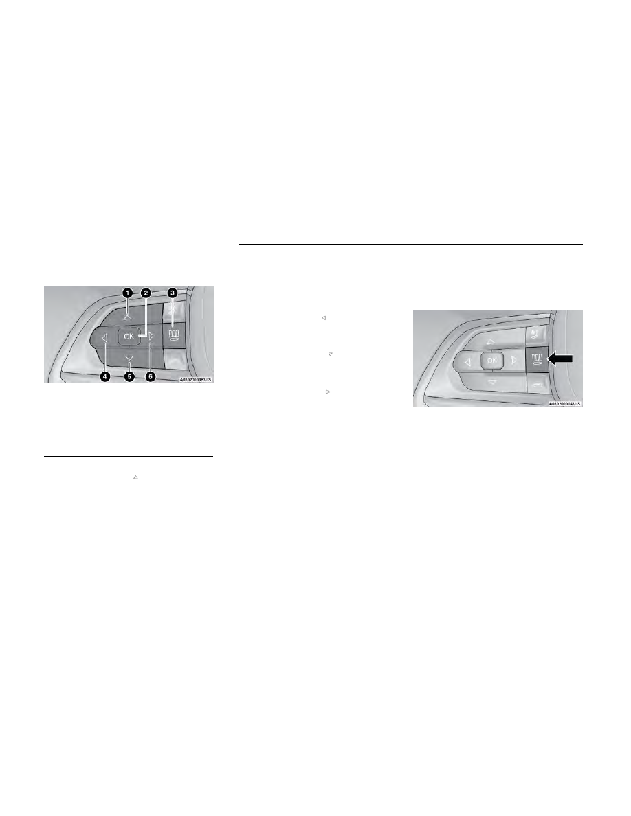
The systems allow the driver to select information by
pushing the following buttons mounted on the steering
wheel:

Up Arrow Button

Push and release the

up

arrow button to scroll

upward through the main menu and submenus.

OK Button

Push the

OK

button to access/select the informa-

tion screens or submenu screens of a main menu
item. Push and hold the

OK

button for one second

to reset displayed/selected features that can be
reset.

Menu Button

— If Equipped

Push the

Menu

button to access/select the informa-

tion screens or submenu screens of the Home
Screen display. Push and hold the

OK

button to

enter edit mode.

Left Arrow Button

Push and release the

left

arrow button to access

the information screens or submenu screens of a
main menu item.

Down Arrow Button

Push and release the

down

arrow button to

scroll downward through the main menu and
submenus.

Right Arrow Button

Push and release the

right

arrow button to

access the information screens or submenu screens
of a main menu item.

Display Options — If Equipped

Holding

OK

will also allow you to change your display to

Digital or Analog.

Digital theme will be the default theme

Menu screen times out after 10 seconds. Press

OK

to reactivate

Speedometer must always be present

Relevant warning notifications and other pop-up info
will still be displayed in the main screen area (In this
case the speed moves to the top)

Custom Tile Configuration

To customize the instrument cluster further, you are
able to select up to five tiles to display information
based on your needs.

Press the

MENU

button for the Home Screen display

Navigate

Left

or

Right

to highlight desired tile

Press

OK

to select the tile and navigate to the

selected submenu and press

OK

again to add your

selection to your tile view

If equipped, the main menu options of the home
screen are Navigation, Vehicle Info, Driver Info,
Audio, and Off Road

Premium Instrument Cluster Display Control Buttons

1 — Up Arrow Button
2 — OK Button
3 — Menu Button
4 — Left Arrow Button
5 — Down Arrow Button
6 — Right Arrow Button

Menu Button

66

GETTING TO KNOW YOUR INSTRUMENT PANEL
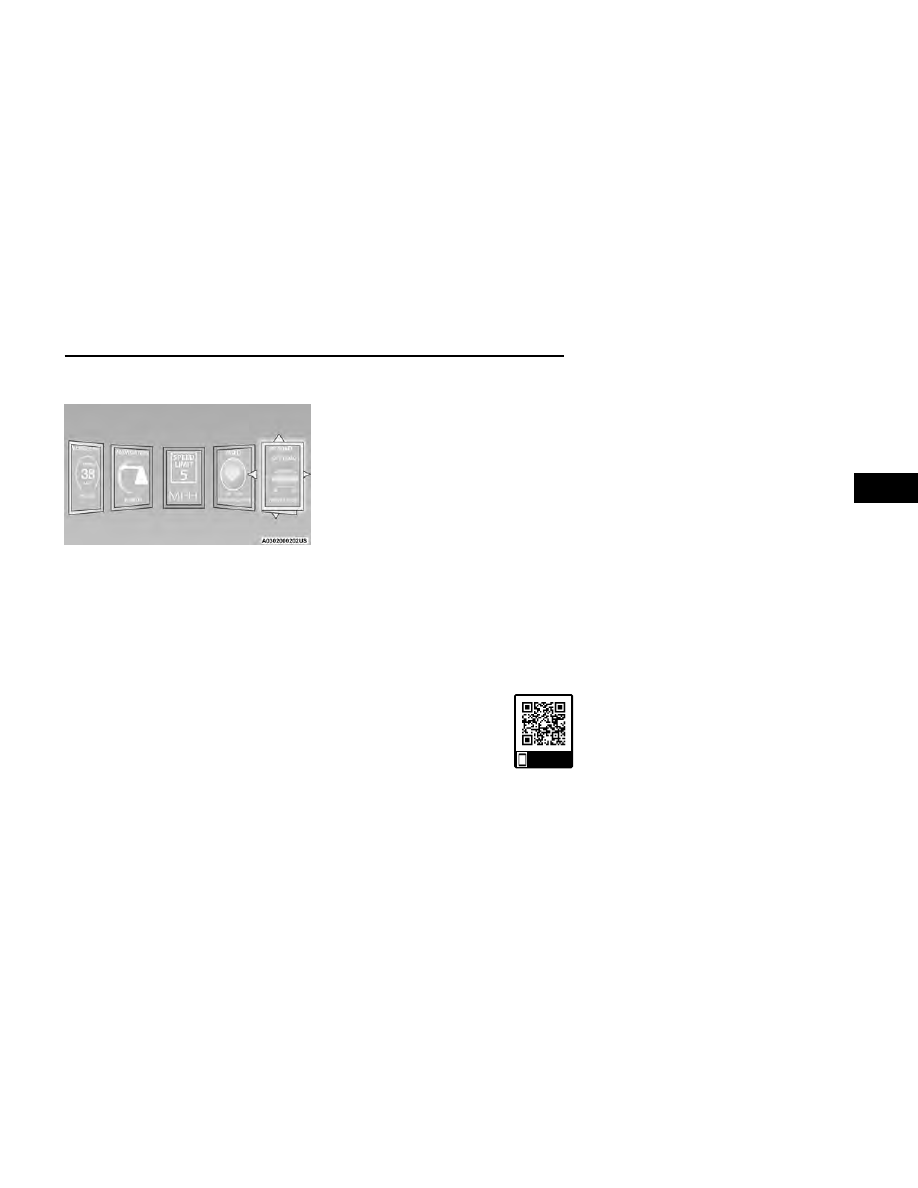
You can customize your Instrument Cluster Display with
up to five tiles that may consist of the following:

NOTE:

These options may vary based on your vehicle trim
level.

Home Screen Options

Navigation — If Equipped

Route Set / Route Not Set

Trip A / Trip B

Vehicle Info

Coolant Temp

Trans Temp

Oil Temp

Oil Pressure

Battery Voltage

Oil Life

Tire Pressure

Fuel Economy

Driver Info — If Equipped

Posted Speed Limit Sign

Driver Assist

Audio

Audio Info

Off Road — If Equipped

Selec-Terrain / Air Suspension Status

Steering Angle

Pitch

Roll

The instrument cluster display is located in the center
portion of the cluster and consist of multiple sections:

Main Screen — The inner ring of the display will illu-
minate in gray under normal conditions, yellow for
noncritical warnings, red for critical warnings, and
white for on demand information.

Submenu Dots — Whenever there are submenus
available, the position within the submenus is
shown here.

Reconfigurable Telltales/Information

Gear Selector Status (PRND)

Driver Interactive Display (Compass, Temp, Range to
Empty, Trip A, Trip B, Average Fuel Economy, Current
Fuel Economy and Time)

Four-Wheel Drive (4WD) Status — If Equipped

OIL CHANGE RESET

Use this QR code to access your digital
experience.

Your vehicle is equipped with an
engine oil change indicator system.
The “Oil Change Due” message will
display in the instrument cluster dis-
play for five seconds after a single chime has
sounded, to indicate the next scheduled oil change

interval. The engine oil change indicator system is
duty cycle based, which means the engine oil
change interval may fluctuate, dependent upon your
personal driving style.

Unless reset, this message will continue to display
each time the ignition is cycled to the ON/RUN
position.

To reset the oil change indicator after performing the
scheduled maintenance, refer to the following
procedure:

1. Without pressing the brake pedal, push the ENGINE

START/STOP button and cycle the ignition to the
ON/RUN position (do not start the engine).

2. Fully press the accelerator pedal, slowly, three times

within ten seconds.

3. Cycle the ignition to the OFF position.

NOTE:

If the indicator message illuminates when you start the
vehicle, the oil change indicator system did not reset. If
necessary, repeat this procedure.

Custom Tile Screen

Scan me

GETTING TO KNOW YOUR INSTRUMENT PANEL

67

3

DISPLAY AND MESSAGES — IF EQUIPPED

Includes the following, but not limited to:

Front Seat Belts Unbuckled

Driver Seat Belt Unbuckled

Passenger Seat Belt Unbuckled

Traction Control Off

Washer Fluid Low

Oil Pressure Low

Oil Change Due

Fuel Low

Service Anti-lock Brake System

Service Electronic Throttle Control

Service Power Steering

Cruise Off

Cruise Ready

ACC Override

Cruise Set To XXX mph or km/h

Service Shifter

Tire Pressure Screen With Low Tire(s)

Service Tire Pressure System

Park Brake Engaged

Brake Fluid Low

Engine Temperature Hot

Lights On

Right Front Turn Signal Light Out

Right Rear Turn Signal Light Out

Left Front Turn Signal Light Out

Left Rear Turn Signal Light Out

Ignition or Accessory On

Vehicle Not In Park

Remote Start Active Push Start Button

Remote Start Canceled Fuel Low

Remote Start Canceled Door Open

Remote Start Canceled Hood Open

Remote Start Canceled Liftgate Open

Remote Start Canceled Time Expired

Remote Start Disabled Start To Reset

Service Air Bag System

Service Air Bag Warning Light

Door(s) Open

Service Transmission

Liftgate Open

Hood Open

Shift Not Allowed

Vehicle Speed Too High To Shift to D

Vehicle Speed is Too High to Shift to R

Vehicle Speed is Too High to Shift to P

The Reconfigurable Telltales section is divided into the
white or yellow telltales area on the left, and the green
or red telltales area on the right.

The instrument cluster display will normally display the
main menu or the screens of a selected feature of the
main menu. The main display area also displays pop-up
messages that consist of approximately 60 possible
warning or information messages. These pop-up mes-
sages fall into several categories:

Five Second Stored Messages

When the appropriate conditions occur, this type of
message takes control of the main display area for
five seconds and then returns to the previous

screen. Most of the messages of this type are then
stored (as long as the condition that activated it
remains active) and can be reviewed from the “Mes-
sages” main menu item. Examples of this message
type are “Right Front Turn Signal Lamp Out” and
“Low Tire Pressure.”

Unstored Messages

This message type is displayed indefinitely or until
the condition that activated the message is cleared.
Examples of this message type are “Turn Signal On”
(if a turn signal is left on) and “Lights On” (if driver
leaves the vehicle with the lights on).

Unstored Messages Until RUN

These messages deal primarily with the Remote
Start feature. This message type is displayed until
the ignition is in the RUN state. Examples of this
message type are “Remote Start Canceled - Door
Ajar” and “Press Brake Pedal and Push Button to
Start.”

Five Second Unstored Messages

When the appropriate conditions occur, this type of
message takes control of the main display area for
five seconds and then returns to the previous
screen. An example of this message type is “Auto-
matic High Beams On.”

68

GETTING TO KNOW YOUR INSTRUMENT PANEL

INSTRUMENT CLUSTER DISPLAY
MENU ITEMS

The instrument cluster display can be used to view the
main menu items for several features. Use the

up

and

down

arrow buttons to scroll through the

driver interactive display menu options until the desired
menu is reached.

NOTE:

The instrument cluster display menu items display in
the center of the instrument cluster. Menu items may
vary depending on your vehicle features.

Main Menu

DRIVER INFO — IF EQUIPPED

Base/Midline Cluster

Speedometer

Push and release the

up

or

down

arrow button

until the Speedometer Menu item is displayed in the
instrument cluster display. Push and release the

OK

button to change the speedometer scale from MPH
to km/h (or vice versa).

Premium Cluster

Speedometer

Push and release the

up

or

down

arrow button

until the Speedometer Menu item is displayed in the
instrument cluster display. Push and release the

OK

button to change the speedometer scale from MPH
to km/h (or vice versa).

Driver Assist

Push and release the

up

or

down

arrow button

until the Driver Assist menu icon is displayed in the
instrument cluster display. Push and release the

OK

button to select. The Driver Assist screen indicates the
current status of ACC, Active Lane Management and
Highway Assist/Assist+/Pilot. Push and release the

OK

button to again to change between Zoomed In and
Zoomed Out view (“Press OK to Zoom In” will display
when in Zoomed Out view/“Press OK to Zoom Out” will
display when in Zoomed In view).

VEHICLE INFO (CUSTOMER INFORMATION
FEATURES)

Push and release the

up

or

down

arrow button

until the Vehicle Info Menu item is displayed in the
instrument cluster display. Push and release the

left

or

right

arrow button to cycle through the

Vehicle Info submenus and follow the prompts on each
screen as needed.

Base/Midline Cluster

1.

Tire Pressure

If tire pressure is correct for all tires a vehicle
icon is displayed with tire pressure values in
each corner of the icon.

If one or more tires have low pressure, “Inflate
Tire To XX” is displayed with the vehicle icon and
the tire pressure values in each corner of the
icon with the pressure value of the low tire dis-
played in a different color than the other tire
pressure value.

If the Tire Pressure system requires service,
“Service Tire Pressure System” is displayed.

Tire PSI is an information only function and can-
not be reset

page 162.

2.

Coolant Temperature

Displays the actual coolant temperature.

3.

Transmission Temperature — Automatic
Transmission Only

Displays the actual transmission temperature.

4.

Oil Temperature

Displays the level of oil temperature.

5.

Battery Voltage

Displays the actual battery voltage.

Premium Cluster

Fuel Economy

page 70

Average Fuel Economy

Current Fuel Economy/Sailing Active Status Indi-
cation

page 80

Range To Empty

NOTE:

Significant changes in driving style or vehicle load-
ing will greatly affect the actual drivable distance of
the vehicle, regardless of the Range displayed value.

Gauge Summary

Coolant Temp

Trans Temp

Oil Temp

Oil Pressure

Battery Voltage

Tire Pressure

If tire pressure is

OK

for all tires a vehicle ICON is

displayed with tire pressure values in each corner
of the ICON.

If one or more tires have low pressure, “Inflate
Tire To XX” is displayed with the vehicle ICON and
the tire pressure values in each corner of the
ICON with the pressure value of the low tire dis-
played in a different color than the other tire
pressure value.

GETTING TO KNOW YOUR INSTRUMENT PANEL

69

3

If the Tire Pressure system requires service,
“Service Tire Pressure System” is displayed.

Tire PSI is an information only function and
cannot be reset

page 162.

Stop/Start Status

Display the status of the Stop/Start system.

DRIVER ASSIST

Push and release the

up

or

down

arrow button

until the Driver Assist menu title is highlighted in the
instrument cluster display.

The instrument cluster display displays the current ACC
system settings. The information displayed depends on
ACC system status.

Push the Adaptive Cruise Control (ACC) ON/OFF button
(located on the steering wheel) until one of the follow-
ing displays in the instrument cluster display:

Adaptive Cruise Control Off

When ACC is deactivated, the display will read “Adaptive
Cruise Control Off.”

Adaptive Cruise Control Ready

When ACC is activated but the vehicle speed setting
has not been selected, the display will read “Adaptive
Cruise Control Ready.”

Push and release the SET + or the SET- button (located
on the steering wheel) and the following will display in
the instrument cluster display:

ACC SET

When ACC is set, the set speed will display in the instru-
ment cluster.

The ACC screen may display once again if any ACC activ-
ity occurs, which may include any of the following:

Distance Setting Change

System Cancel

Driver Override

System Off

ACC Proximity Warning

ACC Unavailable Warning

NOTE:

The instrument cluster display will return to the last
display selected after five seconds of no ACC display
activity

page 97.

The instrument cluster display displays the current
Active Lane Management system settings. The informa-
tion displayed depends on Active Lane Management
system status and the conditions that need to be met

page 118.

FUEL ECONOMY

Push and release the

up

or

down

arrow button

until the Fuel Economy menu title is displayed in the
instrument cluster display. Push and hold the

OK

button

to reset average fuel economy feature.

Average Fuel Economy– The display shows the aver-
age fuel economy (MPG, or L/100 km, or km/L)
since the last reset.

Current Fuel Economy/Sailing Active Status Indica-
tion – This display shows the current fuel economy
(MPG, or L/100 km, or km/L) while driving as well
as indicating when the Idle Coasting feature if
enabled and active

page 80.

Range To Empty – The display shows the estimated
distance (mi or km) that can be traveled with the
fuel remaining in the tank. When the Range value is
less than 30 miles (48 km) estimated driving dis-
tance, the Range display will change to a “LOW
FUEL” message. Adding a significant amount of fuel

to the vehicle will turn off the “LOW FUEL” message
and a new Range value will display. Range cannot
be reset through the

OK

button.

NOTE:

Significant changes in driving style or vehicle load-
ing will greatly affect the actual drivable distance of
the vehicle, regardless of the Range displayed value.

TRIP INFO

Push and release the

up

or

down

arrow button

until the Trip menu title is displayed in the instrument
cluster display. Toggle the

left

or

right

arrow but-

ton to select Trip A or Trip B. The Trip information will
display the following:

Distance – Shows the total distance (mi or km) trav-
eled for Trip A or Trip B since the last reset.

Average Fuel Economy – Shows the average fuel
economy (MPG or L/100 km or km/L) of Trip A or
Trip B since the last reset.

Elapsed Time – Shows the total elapsed time of
travel since Trip A or Trip B has been reset.

Hold the

OK

button to reset feature information.

OFF ROAD — IF EQUIPPED

Push and release the

up

or

down

arrow button

until the Off Road Menu icon/title is highlighted. Push
the

left

or

right

arrow button to scroll the

submenus.

Terrain Status

Selec-Terrain Status

70

GETTING TO KNOW YOUR INSTRUMENT PANEL

STOP/START – IF EQUIPPED

Push and release the

up

or

down

arrow button

until the Stop/Start menu title is displayed in the instru-
ment cluster display.

AUDIO

Push and release the

up

or

down

arrow button

until the Audio menu title is displayed in the instrument
cluster display.

STORED MESSAGES

Push and release the

up

or

down

arrow button

until the Messages Menu Icon is highlighted in the
instrument cluster display. This feature shows the num-
ber of stored warning messages. Pushing the

left

or

right

arrow button will allow you to scroll through the

stored messages.

SCREEN SETUP

Push and release the

up

or

down

arrow button

until the Screen Setup Menu Icon/Title is highlighted in
the instrument cluster display. Push and release the

OK

button to enter the submenus and follow the prompts
on the screen as needed. The Screen Setup feature
allows you to change what information is displayed in
the instrument cluster as well as the location that infor-
mation is displayed.

Screen Setup Driver Selectable Items

NOTE:

Based on vehicle trim level and current status, some of
the following options may not be available.

Base/Midline Cluster

Upper Left or Upper Right

None

Compass

Outside Temp

Date

Time

Ignition State
(Keyless Ignition
Only)

Range To Empty

Average
Economy

Current
Economy

Center

None

Range to Empty

Date

Average
Economy

Current
Economy

Outside Temp

Compass

Menu Title

Audio Info

Time

Trip A Distance

Speedometer

Trip B Distance

Restore Defaults

Ok

Cancel

Premium Cluster

Upper Left or Upper Right

None

Range To Empty

Date

Outside Temp

Current
Economy

Ignition State

Time

Compass

Average
Economy

Trip A

Trip B

Odometer

- Premium Cluster Only

Show

Hide

Favorites

Driver Info

Vehicle Info

Trip

Off Road

Audio

Stored
Messages

Settings

Defaults

Restore

Cancel

VEHICLE SETTINGS — IF EQUIPPED

Push and release the

up

or

down

arrow button

until the Vehicle Setup Menu item is displayed in the
instrument cluster display. This menu item allows you to
change the settings for the following:

Display

Navigation Repetition

Security

Passenger Airbag

Seat Belt Reminder

Safety and Assistance

Hill Start Assist

NOTE:

Most vehicle settings will be moved into the radio if a
touchscreen radio is present

page 133.

GETTING TO KNOW YOUR INSTRUMENT PANEL

71

3

Display

By selecting Display, the following settings can be
selected:

Language: select the language in which to display
the information/warnings.

Phone Repetition: displays information relating to
the phone mode.

Units

By selecting Units, the unit of measurement to use for
displaying various values can be set. Possible options are:

US

Metric

Custom: allows individual changes of units for tem-
perature, distance, consumption, and tire pressure.

Clock And Date

By selecting Clock and Date, the time and date can be
set. Possible options are:

Set Time: adjust hours/minutes

Set Format: adjust the time format “12h” (12 hours)
or “24h” (24 hours)

Set Date: adjust day/month/year

Security

Passenger Air Bag Disable (PAD): a selection of Passen-
ger Air Bag Disable (ON/OFF) may be made if a child
restraint must be installed in the front seat.

Safety And Assistance

By selecting the item Safety and Assistance, the follow-
ing adjustments can be made:

ParkSense (If Equipped): a selection of the type of
information provided by ParkSense

Front ParkSense Volume (If Equipped): selection of
the volume of the beeps provided by the front
ParkSense

Rear ParkSense Volume (If Equipped): selection of
the volume of the beeps provided by the rear
ParkSense

Forward Collision Warning (FCW) (If Equipped): a
selection of operating modes of the system Forward
Collision Warning Plus

FCW Sensitivity (If Equipped): a selection of the
“readiness” of intervention of the Forward Collision
Warning Plus system, based on the distance to the
obstacle

Rain Sensing Wipers (If Equipped): enabling/
disabling the automatic operation of wipers in the
event of rain

Active Lane Management Force (If Equipped): selec-
tion of the force to be applied to the steering wheel
to put the car in the roadway through the system of
electrical drive, in case of operation of the system
Active Lane Management

Active Lane Management Warning (If Equipped): a
selection of the “readiness” of intervention of Active
Lane Management

Buzzer Volume: There are 4 options: Off, Low,
Medium, Loud

Brake Service (If Equipped): activation of the proce-
dure to carry out braking system maintenance

Auto Park Brake (If Equipped): enable/disable auto
insertion of the Electric Park Brake

Hill Start Assist: Activation/Deactivation of the Hill
Start Assist system

Lights — If Equipped

By selecting Lights, the following adjustments can be
made:

Ambient Lights (If Equipped): adjust the sensitivity
of lighting in the doors and overhead console

Lights Off Delay: set the delay for headlight shutoff
after engine shutoff

Headlight Sensitivity: adjust the sensitivity of head-
light brightness

Greeting Lights: activate the direction indicators
when unlocking the doors

Daytime Lights (If Equipped): activate/deactivate
the daytime running lights

Cornering Lights (If Equipped): activate/deactivate
the cornering lights

Auto High Beam (If Equipped): activate/deactivate
the automatic high beam headlights

Doors And Locks

By selecting Doors and Locks, the following adjust-
ments can be made:

Auto Unlock Doors: automatic unlocking of the
doors when exiting the vehicle

Lights with Lock: activate the direction indicators
when locking the doors

Horn With Remote Lock: activate/deactivate the
horn when pressing the lock button on the key. The
options are “Off”, “First Press”, and “Second Press”

Horn With Remote Start (If Equipped): activate/
deactivate the horn at the Remote Starting of the
engine with the key

Door Unlock: allow you to choose whether to unlock
all the doors or only the driver’s side door on the
first push of the unlock button on the key

Auto Driver Comfort (If Equipped): activate/
deactivate automatic climate control during vehicle
starts

Key in Memory (If Equipped): activate/deactivate
memory linked to a key

72

GETTING TO KNOW YOUR INSTRUMENT PANEL

Compass

By selecting Compass, the following settings can be
changed:

Calibration (If Equipped)

This compass is self-calibrating, which eliminates the
need to set the compass manually. When the vehicle is
new, the compass may appear erratic, and the cluster
will display dashes (- -) until the compass is calibrated.
You may also calibrate the compass by completing one
or more 360 degree turns (in an area free from large
metal or metallic objects) until the dashes (- -) displayed
in the instrument cluster display turns off. The compass
will now function normally.

Variance (If Equipped)

Compass Variance is the difference between Magnetic
North and Geographic North. To compensate for the
differences, the variance should be set for the zone
where the vehicle is driven, per the zone map. Once
properly set, the compass will automatically compen-
sate for the differences and provide the most accurate
compass heading.

BATTERY SAVER ON/BATTERY
SAVER MODE MESSAGE —
ELECTRICAL LOAD REDUCTION
ACTIONS — IF EQUIPPED

This vehicle is equipped with an Intelligent Battery Sen-
sor (IBS) to perform additional monitoring of the electri-
cal system and status of the vehicle battery.

In cases when the IBS detects charging system failure,
or the vehicle battery conditions are deteriorating, elec-
trical load reduction actions will take place to extend
the driving time and distance of the vehicle. This is
done by reducing power to or turning off non-essential
electrical loads.

Load reduction is only active when the engine is run-
ning. It will display a message if there is a risk of battery
depletion to the point where the vehicle may stall due
to lack of electrical supply, or will not restart after the
current drive cycle.

When load reduction is activated, the message “Battery
Saver On” or “Battery Saver Mode” will appear in the
instrument cluster display.

These messages indicate the vehicle battery has a low
state of charge and continues to lose electrical charge
at a rate that the charging system cannot sustain.

NOTE:

The charging system is independent from load
reduction. The charging system performs a diagnos-
tic on the charging system continuously.

If the Battery Charge Warning Light is on it may indi-
cate a problem with the charging system

page 75.

The following are electrical loads that may be switched
off (if equipped), and vehicle functions which can be
affected by load reduction:

Heated Seat/Vented Seats/Heated Wheel

Heated/Cooled Cup Holders — If Equipped

Rear Defroster And Heated Mirrors

HVAC System

150W Power Inverter System

Audio and Telematics System

Loss of the battery charge may indicate one or more of
the following conditions:

The charging system cannot deliver enough electri-
cal power to the vehicle system because the electri-
cal loads are larger than the capability of charging
system. The charging system is still functioning
properly.

Turning on all possible vehicle electrical loads (e.g.
HVAC to max settings, exterior and interior lights,
overloaded power outlets +12 Volts, 150W, USB
ports) during certain driving conditions (city driving,
towing, frequent stopping).

Installing options like additional lights, upfitter elec-
trical accessories, audio systems, alarms and simi-
lar devices.

Unusual driving cycles (short trips separated by long
parking periods).

The vehicle was parked for an extended period of
time (weeks, months).

The battery was recently replaced and was not
charged completely.

The battery was discharged by an electrical load left
on when the vehicle was parked.

Compass Variance Map

GETTING TO KNOW YOUR INSTRUMENT PANEL

73

3

The battery was used for an extended period with
the engine not running to supply radio, lights, char-
gers, +12 Volts portable appliances like vacuum
cleaners, game consoles and similar devices.

What to do when an electrical load reduction action
message is present (“Battery Saver On” or “Battery
Saver Mode”)

During a trip:

Reduce power to unnecessary loads if possible:

Turn off redundant lights (interior or exterior)

Check what may be plugged into power outlets
+12 Volts, 150W, USB ports

Check HVAC settings (blower, temperature)

Check the audio settings (volume)

After a trip:

Check if any aftermarket equipment was installed
(additional lights, upfitter electrical accessories,
audio systems, alarms) and review specifications if
any (load and Ignition Off Draw currents).

Evaluate the latest driving cycles (distance, driving
time and parking time).

The vehicle should have service performed if the
message is still present during consecutive trips
and the evaluation of the vehicle and driving pattern
did not help to identify the cause.

WARNING LIGHTS AND MESSAGES

The warning/indicator lights will illuminate in the instru-
ment panel together with a dedicated message and/or
acoustic signal when applicable. These indications are
indicative and precautionary and as such must not be
considered as exhaustive and/or alternative to the
information contained in the Owner’s Manual, which
you are advised to read carefully in all cases. Always

refer to the information in this chapter in the event of a
failure indication. All active telltales will display first if
applicable. The system check menu may appear differ-
ent based upon equipment options and current vehicle
status. Some telltales are optional and may not appear.

RED WARNING LIGHTS

Air Bag Warning Light

This warning light will illuminate to indicate a
fault with the air bag, and will turn on for
four to eight seconds as a bulb check when
the ignition is placed in the ON/RUN posi-

tion. This light will illuminate with a single chime when a
fault with the air bag has been detected, it will stay on
until the fault is cleared. If the light is either not on dur-
ing startup, stays on, or turns on while driving, have the
system inspected at an authorized dealer as soon as
possible.

Brake Warning Light

This warning light monitors various brake
functions, including brake fluid level and
parking brake application. If the brake light
turns on it may indicate that the parking

brake is applied, that the brake fluid level is low, or that
there is a problem with the Anti-Lock Brake System
reservoir.

If the light remains on when the parking brake has
been disengaged, and the fluid level is at the full mark
on the master cylinder reservoir, it indicates a possible
brake hydraulic system malfunction or that a problem
with the Brake Booster has been detected by the Anti-
Lock Brake System (ABS) / Electronic Stability Control
(ESC) system. In this case, the light will remain on until
the condition has been corrected. If the problem is

related to the brake booster, the ABS pump will run
when applying the brake, and a brake pedal pulsation
may be felt during each stop.

The dual brake system provides a reserve braking
capacity in the event of a failure to a portion of the
hydraulic system. A leak in either half of the dual brake
system is indicated by the Brake Warning Light, which
will turn on when the brake fluid level in the master
cylinder has dropped below a specified level.

The light will remain on until the cause is corrected.

NOTE:

The light may flash momentarily during sharp cornering
maneuvers, which change fluid level conditions. The
vehicle should have service performed, and the brake
fluid level checked.

If brake failure is indicated, immediate repair is
necessary.

WARNING!

Driving a vehicle with the red brake light on is danger-
ous. Part of the brake system may have failed. It will
take longer to stop the vehicle. You could have a colli-
sion. Have the vehicle checked immediately.

Vehicles equipped with the Anti-Lock Brake System
(ABS) are also equipped with Electronic Brake Force
Distribution (EBD). In the event of an EBD failure, the
Brake Warning Light will turn on along with the ABS
Light. Immediate repair to the ABS system is required.

Operation of the Brake Warning Light can be checked
by turning the ignition switch from the OFF position to
the ON/RUN position. The light should illuminate for
approximately two seconds. The light should then turn

74

GETTING TO KNOW YOUR INSTRUMENT PANEL

off unless the parking brake is applied or a brake fault
is detected. If the light does not illuminate, have the
light inspected by an authorized dealer.

The light also will turn on when the parking brake is
applied with the ignition switch in the ON/RUN position.

NOTE:

This light shows only that the parking brake is applied.
It does not show the degree of brake application.

Battery Charge Warning Light

This warning light will illuminate when the
battery is not charging properly. If it stays on
while the engine is running, there may be a
malfunction with the charging system. Con-

tact an authorized dealer as soon as possible.

This indicates a possible problem with the electrical
system or a related component.

Door Open Warning Light

This indicator will illuminate when a door is
ajar/open and not fully closed.

NOTE:

If the vehicle is moving, there will also be a single
chime.

Drowsiness Detected Warning Light —

If Equipped

Driver drowsiness detection helps to avoid
crashes caused by fatigue by advising driv-
ers to take a break in time. Once Drowsy
Driver is detected, A pop-up will display con-

tinuously until the driver presses the

OK

button to clear.

Once the pop-up message is cleared, it is stored until
the condition is no longer true.

Electric Power Steering (EPS) Fault

Warning Light

This warning light will turn on when there's a
fault with the EPS system

page 93.

WARNING!

Continued operation with reduced assist could pose a
safety risk to yourself and others. Service should be
obtained as soon as possible.

Electronic Throttle Control (ETC) Warning

Light

This warning light will illuminate to indicate a
problem with the ETC system. If a problem is
detected while the vehicle is running, the
light will either stay on or flash depending on

the nature of the problem. Cycle the ignition when the
vehicle is safely and completely stopped and the trans-
mission is placed in the PARK position. The light should
turn off. If the light remains on with the vehicle running,
your vehicle will usually be drivable; however, see an
authorized dealer for service as soon as possible.

NOTE:

This light may turn on if the accelerator and brake ped-
als are pressed at the same time.

If the light continues to flash when the vehicle is run-
ning, immediate service is required and you may experi-
ence reduced performance, an elevated/rough idle, or

engine stall and your vehicle may require towing. The
light will come on when the ignition is placed in the
ON/RUN position and remain on briefly as a bulb
check. If the light does not come on during starting,
have the system checked by an authorized dealer.

Engine Temperature Warning Light

This warning light will illuminate to warn of
an overheated engine condition. If the
engine coolant temperature is too high, this
light will illuminate and a single chime will

sound.

If the light turns on while driving, safely pull over and
stop the vehicle. If the Air Conditioning (A/C) system is
on, turn it off. Also, shift the transmission into NEUTRAL
(N) and idle the vehicle. If the temperature reading
does not return to normal, turn the engine off immedi-
ately and call for service

page 205.

Hood Open Warning Light

This warning light will illuminate when the
hood is left open and not fully closed.

NOTE:

If the vehicle is moving, there will also be a single chime.

Liftgate Open Warning Light

This warning light will illuminate when the
liftgate is open.

NOTE:

If the vehicle is moving, there will also be a single chime.

GETTING TO KNOW YOUR INSTRUMENT PANEL

75

3

Oil Pressure Warning Light

This warning light will illuminate to indicate
low engine oil pressure. If the light turns on
while driving, stop the vehicle, shut off the
engine as soon as possible, and contact an

authorized dealer. A chime will sound when this light
turns on.

Do not operate the vehicle until the cause is corrected.
This light does not indicate how much oil is in the
engine. The engine oil level must be checked under the
hood.

Oil Temperature Warning Light

This warning light will illuminate to indicate
the engine oil temperature is high. If the light
turns on while driving, stop the vehicle and
shut off the engine as soon as possible. Wait

for oil temperature to return to normal levels.

Seat Belt Reminder Warning Light

This warning light indicates when the driver
or passenger seat belt is unbuckled. When
the ignition is first placed in the ON/RUN
position and if the driver’s seat belt is

unbuckled, a chime will sound and the light will turn on.
When driving, if the driver or front passenger seat belt
remains unbuckled, the Seat Belt Reminder Light will
flash or remain on continuously and a chime will sound

page 165.

Transmission Fault Warning Light

This light will illuminate (together with a mes-
sage in the instrument cluster display and a
buzzer) to indicate a transmission fault. Con-
tact an authorized dealer if the message

remains after restarting the engine.

Transmission Temperature Warning

Light

This warning light will illuminate to warn of a
high transmission fluid temperature. This
may occur with strenuous usage such as
trailer towing. If this light turns on, stop the

vehicle and run the engine at idle or slightly faster, with
the transmission in PARK or NEUTRAL, until the light
turns off. Once the light turns off, you may continue to
drive normally.

WARNING!

If you continue operating the vehicle when the Trans-
mission Temperature Warning Light is illuminated you
could cause the fluid to boil over, come in contact
with hot engine or exhaust components and cause a
fire.

CAUTION!

Continuous driving with the Transmission Tempera-
ture Warning Light illuminated will eventually cause
severe transmission damage or transmission failure.

Vehicle Security Warning Light —

If Equipped

This light will flash at a fast rate for approxi-
mately 15 seconds when the Vehicle Secu-
rity system is arming, and then will flash
slowly until the vehicle is disarmed.

YELLOW WARNING LIGHTS

Anti-Lock Brake System (ABS) Warning

Light

This warning light monitors the ABS. The
light will turn on when the ignition is placed
in the ON/RUN position and may stay on for
as long as four seconds.

If the ABS light remains on or turns on while driving,
then the Anti-Lock portion of the brake system is not
functioning and service is required as soon as possible.
However, the conventional brake system will continue to
operate normally, assuming the Brake Warning Light is
not also on.

If the ABS light does not turn on when the ignition is
placed in the ON/RUN position, have the brake system
inspected by an authorized dealer.

Electric Park Brake Warning Light

This warning light will illuminate to indicate
the Electric Park Brake is not functioning
properly and service is required. Contact an
authorized dealer.

76

GETTING TO KNOW YOUR INSTRUMENT PANEL

Electronic Stability Control (ESC) Active

Warning Light — If Equipped

This warning light will indicate when the ESC
system is Active. The ESC Indicator Light in
the instrument cluster will come on when the
ignition is placed in the ON/RUN position,

and when ESC is activated. It should go out with the
engine running. If the ESC Indicator Light comes on
continuously with the engine running, a malfunction
has been detected in the ESC system. If this warning
light remains on after several ignition cycles, and the
vehicle has been driven several miles (kilometers) at
speeds greater than 30 mph (48 km/h), see an autho-
rized dealer as soon as possible to have the problem
diagnosed and corrected.

The ESC OFF Indicator Light and the ESC Indicator
Light come on momentarily each time the ignition is
placed in the ON/RUN position.

The ESC system will make buzzing or clicking
sounds when it is active. This is normal; the sounds
will stop when ESC becomes inactive.

This light will come on when the vehicle is in an ESC
event.

Electronic Stability Control (ESC) OFF

Warning Light — If Equipped

This warning light indicates the ESC is off.
Each time the ignition is turned to ON/RUN,
the ESC system will be on, even if it was
turned off previously.

Fuel Cutoff Warning Light — If Equipped

This warning light will illuminate after an
accident has occurred, and the system has
shut the fuel off.

Fuel Level Sensor Failure Warning Light

This light illuminates when there is a fuel
level sensor failure. If this light illuminates,
take it to an authorized dealer and have
them inspect it.

Active Lane Management Warning Light

— If Equipped

The Active Lane Management Warning Light
will be solid yellow when the vehicle is
approaching a lane marker. The warning
light will flash when the vehicle is crossing

the lane marker.

Service Active Lane Management

Warning Light — If Equipped

This warning light will illuminate when the
Active Lane Management system is not oper-
ating and requires service. Please see an
authorized dealer.

Low Coolant Level Warning Light

This telltale will turn on to indicate the
vehicle coolant level is low

page 219.

Low Fuel Warning Light

Depending on whether the tank size is
13.5 gal (51 L) or 15.8 gal (60 L), the Low
Fuel Indicator Light will turn on when the fuel
level goes below 1.5 gal (5.6 L) or 1.7 gal

(6.6 L) respectively.

Low Washer Fluid Warning Light —

If Equipped

This warning light will illuminate when the
windshield washer fluid is low.

Engine Check/Malfunction Indicator

(MIL) Warning Light

The MIL is a part of an Onboard Diagnostic
System called OBD II that monitors engine
and automatic transmission control systems.
This warning light will illuminate when the

ignition is in the ON/RUN position before engine start. If
the bulb does not come on when turning the ignition
switch from OFF to ON/RUN, have the condition
checked promptly.

Certain conditions, such as a loose or missing gas cap,
poor quality fuel, etc., may illuminate the light after
engine start. The vehicle should be serviced if the light
stays on through several typical driving styles. In most
situations, the vehicle will drive normally and will not
require towing.

When the engine is running, the MIL may flash to alert
serious conditions that could lead to immediate loss of
power or severe catalytic converter damage. The
vehicle should be serviced by an authorized dealer as
soon as possible if this occurs.

GETTING TO KNOW YOUR INSTRUMENT PANEL

77

3

WARNING!

A malfunctioning catalytic converter can reach higher
temperatures than in normal operating conditions.
This can cause a fire if you drive slowly or park over
flammable substances such as dry plants, wood,
cardboard, etc. This could result in death or serious
injury to the driver, occupants or others.

CAUTION!

Prolonged driving with the Malfunction Indicator Light
(MIL) on could cause damage to the vehicle control
system. It also could affect fuel economy and drive-
ability. If the MIL is flashing, severe catalytic converter
damage and power loss will soon occur. Immediate
service is required.

Service Adaptive Cruise Control (ACC)

Warning Light — If Equipped

This light will turn on when ACC is not operat-
ing and needs service

page 97.

Service 4WD Warning Light —

If Equipped

This warning light will illuminate to signal a
fault with the 4WD system. If the light stays
on or comes on during driving, it means that
the 4WD system is not functioning properly

and that service is required. We recommend you drive
to the nearest service center and have the vehicle ser-
viced immediately.

Service Forward Collision Warning

(FCW) Light — If Equipped

This warning light will illuminate to indicate a
fault in the Forward Collision Warning Sys-
tem. Contact an authorized dealer for ser-
vice

page 160.

Service Stop/Start System Warning

Light — If Equipped

This warning light will illuminate when the
Stop/Start system is not functioning properly
and service is required. Contact an autho-
rized dealer for service.

Tire Pressure Monitoring System (TPMS)

Warning Light — If Equipped

The warning light switches on and a mes-
sage is displayed to indicate that the tire
pressure is lower than the recommended
value and/or that slow pressure loss is

occurring. In these cases, optimal tire duration and fuel
consumption may not be guaranteed.

Should one or more tires be in the condition mentioned
previously, the display will show the indications corre-
sponding to each tire.

CAUTION!

Do not continue driving with one or more flat tires as
handling may be compromised. Stop the vehicle,
avoiding sharp braking and steering. If a tire puncture
occurs, repair immediately using the dedicated tire
repair kit and contact an authorized dealer as soon
as possible.

Each tire, including the spare (if provided), should be
checked monthly when cold and inflated to the inflation
pressure recommended by the vehicle manufacturer on
the vehicle placard or tire inflation pressure label. If
your vehicle has tires of a different size than the size
indicated on the vehicle placard or tire inflation pres-
sure label, you should determine the proper tire infla-
tion pressure for those tires.

As an added safety feature, your vehicle has been
equipped with a TPMS that illuminates a low tire pres-
sure telltale when one or more of your tires is signifi-
cantly underinflated. Accordingly, when the low tire
pressure telltale illuminates, you should stop and check
your tires as soon as possible, and inflate them to the
proper pressure. Driving on a significantly underinflated
tire causes the tire to overheat and can lead to tire fail-
ure. Underinflation also reduces fuel efficiency and tire
tread life, and may affect the vehicle’s handling and
stopping ability.

Please note that the TPMS is not a substitute for proper
tire maintenance, and it is the driver’s responsibility to
maintain correct tire pressure, even if underinflation
has not reached the level to trigger illumination of the
TPMS low tire pressure telltale.

Your vehicle has also been equipped with a TPMS mal-
function indicator to indicate when the system is not
operating properly. The TPMS malfunction indicator is
combined with the low tire pressure telltale. When the
system detects a malfunction, the telltale will flash for
approximately one minute and then remain continu-
ously illuminated. This sequence will continue upon
subsequent vehicle start-ups as long as the malfunc-
tion exists. When the malfunction indicator is illumi-
nated, the system may not be able to detect or signal
low tire pressure as intended. TPMS malfunctions may
occur for a variety of reasons, including the installation
of replacement or alternate tires or wheels on the

78

GETTING TO KNOW YOUR INSTRUMENT PANEL

vehicle that prevent the TPMS from functioning prop-
erly. Always check the TPMS malfunction telltale after
replacing one or more tires or wheels on your vehicle to
ensure that the replacement or alternate tires and
wheels allow the TPMS to continue to function properly.

CAUTION!

The TPMS has been optimized for the original equip-
ment tires and wheels. TPMS pressures and warning
have been established for the tire size equipped on
your vehicle. Undesirable system operation or sensor
damage may result when using replacement equip-
ment that is not of the same size, type, and/or style.
Aftermarket wheels can cause sensor damage. Using
aftermarket tire sealants may cause the Tire Pressure
Monitoring System (TPMS) sensor to become inoper-
able. After using an aftermarket tire sealant it is rec-
ommended that you take your vehicle to an autho-
rized dealer to have your sensor function checked.

Towing Hook Breakdown Warning Light

— If Equipped

This light illuminates when there is a failure
with the tow hook. Contact an authorized
dealer for service.

YELLOW INDICATOR LIGHTS

4WD Low Indicator Light — If Equipped

This light alerts the driver that the vehicle is
in the 4WD Low mode. The front and rear
driveshafts are mechanically locked together
forcing the front and rear wheels to rotate at

the same speed. Low range provides a greater gear
reduction ratio to provide increased torque at the
wheels

page 92.

4WD Lock Indicator Light

This light alerts the driver that the vehicle is
in the 4WD Lock mode. The front and rear
driveshafts are mechanically locked
together, forcing the front and rear wheels to

rotate at the same speed

page 92.

Auto HOLD! Fault Indicator Light —

If Equipped

The Auto HOLD! Fault Indicator light will illu-
minate if a fault is detected, it will be indi-
cated by a yellow HOLD! indicator light that
will stay on as long as the fault condition

exists.

Forward Collision Warning (FCW)

Indicator Light — If Equipped

This telltale will turn on to warn you of a pos-
sible collision with the vehicle in front of you.

Forward Collision Warning (FCW) OFF

Indicator Light — If Equipped

This indicator light illuminates to indicate
that Forward Collision Warning is off.

Immobilizer Fail/VPS Electrical Alarm

Indicator Light

This telltale will illuminate when the Vehicle
Security system has detected an attempt to
break into the vehicle.

NOTE:

After cycling the ignition to the ON/RUN position, the
Vehicle Security Warning Light could illuminate if a
problem with the system is detected. This condition will
result in the engine being shut off after two seconds.

GREEN INDICATOR LIGHTS

Adaptive Cruise Control (ACC) Set With

No Target Detected Indicator Light —

If Equipped

This light will turn on when the Adaptive
Cruise Control is set and there is no vehicle
in front detected

page 97.

GETTING TO KNOW YOUR INSTRUMENT PANEL

79

3

Adaptive Cruise Control (ACC) Set With

Target Detected Indicator Light —

If Equipped

This light will turn on when the Adaptive
Cruise Control is SET and a vehicle in front is
detected

page 97.

Auto HOLD Indicator Light — If Equipped

Auto HOLD keeps your vehicle at a complete
stop without you having to keep your foot on
the brake pedal. Once engaged a green
HOLD indicator will appear in the Instrument

Cluster Display.

Automatic High Beam Indicator Light —

If Equipped

This indicator shows that the automatic high
beam headlights are on

page 37.

Cruise Control SET Indicator Light

This indicator light will illuminate when the
Cruise Control is set to the desired speed

page 95.

Active Lane Management Indicator Light

— If Equipped

The Active Lane Management indicator light
illuminates solid green when both lane mark-
ings have been detected and the system is
“armed” and ready to provide visual and

torque warnings if an unintentional lane departure
occurs.

Front Fog Indicator Light — If Equipped

This indicator light will illuminate when the
front fog lights are on

page 37.

Parking/Headlights On Indicator Light

This indicator light will illuminate when the
parking lights or headlights are turned on.

Sport Mode Indicator Light

This light will turn on when Sport mode is
active.

Stop/Start Active Indicator Light —

If Equipped

This indicator light will illuminate when the
Stop/Start function is in “Autostop” mode.

Turn Signal Indicator Lights

When the left or right turn signal is activated,
the turn signal indicator will flash indepen-
dently and the corresponding exterior turn
signal lamps will flash. Turn signals can be

activated when the multifunction lever is moved down
(left) or up (right).

NOTE:

A continuous chime will sound if the vehicle is
driven more than 1 mile (1.6 km) with either turn
signal on.

Check for an inoperative outside light bulb if either
indicator flashes at a rapid rate.

WHITE INDICATOR LIGHTS

Cruise Control Ready Indicator Light

This light will turn on when the Cruise Con-
trol has been turned on, but not set

page 95.

Idle Coasting Indicator Light

The Idle Coasting/Sail feature works by
allowing engine speeds to drop to idle, sav-
ing fuel. The indicator is only seen when Idle
Coasting is chosen and active. In addition,

there is indication when this feature is active on the
Fuel Economy menu screen on your Instrument Cluster
Display.

80

GETTING TO KNOW YOUR INSTRUMENT PANEL

Hill Descent Control (HDC) Indicator

Light — If Equipped

This indicator shows when the HDC feature
is turned on. The light will be on solid when
HDC is armed. HDC can only be armed when
the transfer case is in the 4WD Low position

and the vehicle speed is less than 30 mph (48 km/h). If
these conditions are not met while attempting to use
the HDC feature, the HDC indicator light will flash
on/off.

Active Lane Management Indicator Light

— If Equipped

When the Active Lane Management system
is ON, but not armed, the Active Lane Man-
agement indicator light illuminates solid
white. This occurs when only left, right, or

neither lane line has been detected. If a single lane line
is detected, the system is ready to provide only visual
warnings if an unintentional lane departure occurs on
the detected lane line

page 118.

BLUE INDICATOR LIGHTS

High Beam Indicator Light

This indicator light will illuminate to indicate
that the high beam headlights are on. With
the low beams activated, push the multifunc-
tion lever forward (toward the front of the

vehicle) to turn on the high beams. Pull the multifunc-
tion lever rearward (toward the rear of the vehicle) to
turn off the high beams. If the high beams are off, pull
the lever toward you for a temporary high beam on,
“flash to pass” scenario.

ONBOARD DIAGNOSTIC SYSTEM — OBD II

Your vehicle is equipped with a sophisticated Onboard
Diagnostic system called OBD II. This system monitors
the performance of the emissions, engine, and auto-
matic transmission control systems. When these sys-
tems are operating properly, your vehicle will provide
excellent performance and fuel economy, as well as
emissions well within current government regulations.

If any of these systems require service, the OBD II sys-
tem will turn on the Malfunction Indicator Light (MIL). It
will also store diagnostic codes and other information
to assist your service technician in making repairs.
Although your vehicle will usually be drivable and not
need towing, see an authorized dealer for service as
soon as possible.

CAUTION!

Prolonged driving with the MIL on could cause fur-
ther damage to the emission control system. It
could also affect fuel economy and driveability. The
vehicle must be serviced before any emissions
tests can be performed.

If the MIL is flashing while the vehicle is running,

severe catalytic converter damage and power loss
will soon occur. Immediate service is required.

ONBOARD DIAGNOSTIC SYSTEM
(OBD II) CYBERSECURITY

Your vehicle is required to have an OBD II and a connec-
tion port to allow access to information related to the
performance of your emissions controls. Authorized
service technicians may need to access this informa-
tion to assist with the diagnosis and service of your
vehicle and emissions system

page 133.

WARNING!

ONLY an authorized service technician should con-
nect equipment to the OBD II connection port in
order to read the VIN, diagnose, or service your
vehicle.

If unauthorized equipment is connected to the
OBD II connection port, such as a driver-behavior
tracking device, it may:

Be possible that vehicle systems, including safety
related systems, could be impaired or a loss of
vehicle control could occur that may result in an
accident involving serious injury or death.

Access, or allow others to access, information
stored in your vehicle systems, including per-
sonal information.

GETTING TO KNOW YOUR INSTRUMENT PANEL

81

3

EMISSIONS INSPECTION AND
MAINTENANCE PROGRAMS

In some localities, it may be a legal requirement to pass
an inspection of your vehicle's emissions control sys-
tem. Failure to pass could prevent vehicle registration.

For states that require an Inspection and
Maintenance (I/M), this check verifies the
Malfunction Indicator Light (MIL) is function-
ing and is not on when the engine is running,

and that the OBD II system is ready for testing.

Normally, the OBD II system will be ready. The OBD II
system may

not

be ready if your vehicle was recently

serviced, recently had a depleted battery or a battery
replacement. If the OBD II system should be deter-
mined not ready for the I/M test, your vehicle may fail
the test.

Your vehicle has a simple ignition actuated test, which
you can use prior to going to the test station. To check if
your vehicle's OBD II system is ready, you must do the
following:

1. Cycle the ignition switch to the ON position, but do

not crank or start the engine.

NOTE:

If you crank or start the engine, you will have to start
this test over.

2. As soon as you cycle the ignition switch to the ON

position, you will see the Malfunction Indicator Light
(MIL) symbol come on as part of a normal bulb
check.

3. Approximately 15 seconds later, one of two things

will happen:

The MIL will flash for about 10 seconds and
then return to being fully illuminated until you
turn OFF the ignition or start the engine. This
means that your vehicle's OBD II system is

not

ready

and you should

not

proceed to the I/M

station.

The MIL will not flash at all and will remain fully
illuminated until you place the ignition in the off
position or start the engine. This means that
your vehicle's OBD II system is

ready

and you

can proceed to the I/M station.

If your OBD II system is

not ready,

you should see an

authorized dealer or repair facility. If your vehicle was
recently serviced or had a battery failure or replace-
ment, you may need to do nothing more than drive your
vehicle as you normally would in order for your OBD II
system to update. A recheck with the previously men-
tioned test routine may then indicate that the system is

now ready

.

Regardless of whether your vehicle's OBD II system is
ready or not, if the MIL is illuminated during normal
vehicle operation you should have your vehicle serviced
before going to the I/M station. The I/M station can fail
your vehicle because the MIL is on with the engine
running.

82

GETTING TO KNOW YOUR INSTRUMENT PANEL

STARTING AND OPERATING

STARTING THE ENGINE

Before starting your vehicle, adjust your seat, adjust
both inside and outside mirrors, and fasten your seat
belts.

WARNING!

When exiting the vehicle, always remove the key
fob from the vehicle and lock your vehicle.

Never leave children alone in a vehicle, or with
access to an unlocked vehicle.

Allowing children to be in a vehicle unattended is
dangerous for a number of reasons. A child or oth-
ers could be seriously or fatally injured. Children
should be warned not to touch the parking brake,
brake pedal or the transmission gear selector.

Do not leave the key fob in or near the vehicle, or
in a location accessible to children, and do not
leave the ignition of a vehicle equipped with Key-
less Enter ’n Go™ in the ON/RUN position. A child
could operate power windows, other controls, or
move the vehicle.

Do not leave children or animals inside parked
vehicles in hot weather. Interior heat build-up may
cause serious injury or death.

Start the engine with the gear selector in the NEUTRAL
or PARK position. Apply the brake before shifting to any
driving range.

NORMAL STARTING

Place the ignition switch in the START position and
release when the engine starts. If the engine fails to
start within 10 seconds, place the ignition switch in the
LOCK/OFF position, wait 10 to 15 seconds, then repeat
the “Normal Starting” procedure.

Tip Start Feature

Place the ignition switch in the START position and
release it as soon as the starter engages. The starter
motor will continue to run, and will automatically disen-
gage itself when the engine is running. If the engine
fails to start, place the ignition switch in the OFF posi-
tion, wait 10 to 15 seconds, then repeat the “Normal
Starting” procedure.

Automatic Transmission

The gear selector must be in the NEUTRAL or PARK
position before you can start the engine. Apply the
brakes before shifting into any driving gear.

CAUTION!

Damage to the transmission may occur if the follow-
ing precautions are not observed:

Do not shift between PARK, REVERSE, NEUTRAL,
or DRIVE when the engine is above idle speed.

Shift into or out of PARK or REVERSE only after the
vehicle has come to a complete stop.

Before shifting into any gear, make sure your foot
is firmly on the brake pedal.

Keyless Enter ’n Go™ Functions — Using The ENGINE
START/STOP Button

1. The transmission must be in PARK or NEUTRAL.

2. Press and hold the brake pedal while pushing the

ENGINE START/STOP button once.

3. The system starts the vehicle. If the vehicle fails to

start, the starter will disengage automatically after
10 seconds.

4. If you wish to stop the cranking of the engine prior to

the engine starting, push the ENGINE START/STOP
button again.

Keyless Enter ’n Go™ — With Driver’s Foot Off The
Brake Pedal (In PARK Or NEUTRAL Position)

The Keyless Enter ’n Go™ feature operates similar to an
ignition switch. It has three positions, OFF, ON/RUN,
and START. To change the ignition switch positions with-
out starting the vehicle and use the accessories follow,
these steps starting with the ignition switch in the OFF
position:

1. Push the ENGINE START/STOP button once to

change the ignition switch to the ON/RUN position.

2. Push the ENGINE START/STOP button a second time

to change the ignition switch to the OFF position.

COLD WEATHER OPERATION
(BELOW –22°F OR −30°C)

To ensure reliable starting at these temperatures, use
of an externally powered electric engine block heater
(available from an authorized dealer) is recommended.

83

4

EXTENDED PARK STARTING

NOTE:

Extended Park condition occurs when the vehicle has
not been started or driven for at least 30 days.

1. Install a battery charger or jumper cables to the bat-

tery to ensure a full battery charge during the crank
cycle.

2. Place the ignition in the START position and release

it when the engine starts. For Keyless Enter ‘n Go™
ignition systems, press and hold the brake pedal
while pushing the ENGINE START/STOP button once.

3. If the engine fails to start within 10 seconds, place

the ignition in the OFF position, wait 10 to 15 sec-
onds to allow the starter to cool, then repeat the
“Extended Park Starting” procedure.

4. If the engine fails to start after eight attempts, allow

the starter to cool for at least 10 minutes, then
repeat the procedure.

CAUTION!

To prevent damage to the starter, do not crank con-
tinuously for more than 10 seconds at a time. Wait
10 to 15 seconds before trying again.

AFTER STARTING — WARMING UP
THE ENGINE

The idle speed is controlled automatically and it will
decrease as the engine warms up.

IF ENGINE FAILS TO START

If the engine fails to start after you have followed the
“Normal Starting” procedure, and has not experienced
an Extended Park condition as identified in “Extended
Park Starting” procedure, it may be flooded. Push the
accelerator pedal all the way to the floor and hold it
there. Crank the engine for no more than 15 seconds.
This should clear any excess fuel in case the engine is
flooded. Leave the ignition key in the ON/RUN position,
release the accelerator pedal and repeat the “Normal
Starting” procedure.

CAUTION!

To prevent damage to the starter, do not continuously
crank the engine for more than 10 seconds at a time.
Wait 10 to 15 seconds before trying again.

WARNING!

Never pour fuel or other flammable liquid into the
throttle body air inlet opening in an attempt to
start the vehicle. This could result in flash fire
causing serious personal injury.

Do not attempt to push or tow your vehicle to get it
started. Vehicles equipped with an automatic
transmission cannot be started this way. Unburned
fuel could enter the catalytic converter and once
the engine has started, ignite and damage the con-
verter and vehicle.

If the vehicle has a discharged battery, booster
cables may be used to obtain a start from a
booster battery or the battery in another vehicle.
This type of start can be dangerous if done improp-
erly

page 203.

STOPPING THE ENGINE

Vehicles Equipped With Electronic Key
(Keyless Enter ’n Go™):

To shut off the engine with vehicle speed greater than
5 mph (8 km/h), you must push and hold the ignition or
push the ENGINE START/STOP button three times con-
secutively within a few seconds. The engine will shut
down, and the ignition will be placed in the ON/RUN
position.

Turning off the car (placing the ignition from the
ON/RUN position to the OFF position), the power supply
to the accessories are maintained for a period of three
minutes.

Opening the driver’s side door with the ignition in
ON/RUN will sound a short chime that reminds the
driver to place the ignition to OFF.

When the ignition is in the OFF position, the window
switches remain active for three minutes. Opening a
front door will cancel this function.

After severe driving, idle the engine to allow the tem-
perature inside the engine compartment to cool before
shutting off the engine.

ENGINE BREAK-IN RECOMMENDATIONS

A long break-in period is not required for the engine and
drivetrain (transmission and axle) in your vehicle.

Drive moderately during the first 300 miles (500 km).
After the initial 60 miles (100 km), speeds up to 50 or
55 mph (80 or 90 km/h) are desirable.

While cruising, brief full-throttle acceleration within the
limits of local traffic laws contributes to a good break-in.
Wide-open throttle acceleration in low gear can be detri-
mental and should be avoided.

84

STARTING AND OPERATING

The engine oil installed in the engine at the factory is a
high-quality energy conserving type lubricant. Oil
changes should be consistent with anticipated climate
conditions under which vehicle operations will occur.
For the recommended viscosity and quality grades

page 254.

CAUTION!

Never use Non-Detergent Oil or Straight Mineral Oil in
the engine or damage may result.

NOTE:

A new engine may consume some oil during its first few
thousand miles (kilometers) of operation. This should
be considered a normal part of the break-in and not
interpreted as a problem.

PARK BRAKE

ELECTRIC PARK BRAKE (EPB)

Your vehicle is equipped with an EPB system that offers
simple operation, and some additional features that
make the parking brake more convenient and useful.

The parking brake is primarily intended to prevent the
vehicle from rolling while parked. Before leaving the
vehicle, make sure that the parking brake is applied.
Also, be certain to leave the transmission in PARK.

You can engage the parking brake in two ways:

Manually, by applying the EPB switch.

Automatically, by enabling the Auto Park Brake fea-
ture in the Customer Programmable Features sec-
tion of the Uconnect settings

page 133.

The EPB switch is located in the center console.

To apply the parking brake manually, pull up on the switch
momentarily. You may hear a sound from the back of the
vehicle while the parking brake engages. Once the parking
brake is fully engaged, the BRAKE Warning Light in the
instrument cluster and an indicator on the switch will illu-
minate. If your foot is on the brake pedal while you apply
the parking brake, you may notice a small amount of
brake pedal movement. The parking brake can be applied
even when the ignition switch is OFF. The Brake Warning
Light will not illuminate and can only be released when
the ignition switch is in the ON/RUN position.

NOTE:

The EPB Warning Light will illuminate if the EPB switch
is held for longer than 60 seconds in either the
released or applied position. The light will extinguish
upon releasing the switch.

If the Auto Park Brake feature is enabled, the parking
brake will automatically engage whenever the transmis-
sion is placed into PARK. If your foot is on the brake
pedal, you may notice a small amount of brake pedal
movement while the parking brake is engaging.

The parking brake will release automatically when the
ignition switch is ON/RUN, the transmission is in DRIVE
or REVERSE, the driver’s seat belt is buckled, and an
attempt is made to drive away.

To release the parking brake manually, the ignition
switch must be in the ON/RUN position. Put your foot
on the brake pedal, then push the EPB switch down
momentarily. You may hear a sound from the back of
the car while the parking brake disengages. You may
also notice a small amount of movement in the brake
pedal. Once the parking brake is fully disengaged, the
BRAKE Warning Light in the instrument cluster and the
LED indicator on the switch will extinguish.

NOTE:

When parking on a hill, it is important to turn the front
wheels toward the curb on a downhill grade and away
from the curb on an uphill grade. Apply the parking
brake before placing the gear selector in PARK, other-
wise the load on the transmission locking mechanism
may make it difficult to move the gear selector out of
PARK. The parking brake should always be applied
whenever the driver is not in the vehicle.

WARNING!

Do not rely on the parking brake to operate effec-
tively if the rear brakes have been immersed in
water or mud.

Never use the PARK position as a substitute for the
parking brake. Always apply the parking brake fully
when parked to guard against vehicle movement
and possible injury or damage.

When leaving the vehicle, always remove the key
fob from the ignition and lock your vehicle.

(Continued)

Electric Park Brake Switch

STARTING AND OPERATING

85

4

WARNING!

Never leave children alone in a vehicle, or with
access to an unlocked vehicle. Allowing children to
be in a vehicle unattended is dangerous for a num-
ber of reasons. A child or others could be seriously
or fatally injured. Children should be warned not to
touch the parking brake, brake pedal or the gear
selector.

Do not leave the key fob in or near the vehicle, or
in a location accessible to children, and do not
leave the ignition of a vehicle equipped with Key-
less Enter ’n Go™ in the ACC or ON/RUN position.
A child could operate power windows, other con-
trols, or move the vehicle.

Be sure the parking brake is fully disengaged
before driving; failure to do so can lead to brake
failure and a collision.

Always fully apply the parking brake when leaving
your vehicle, or it may roll and cause damage or
injury. Also be certain to leave the transmission in
PARK. Failure to do so may allow the vehicle to roll
and cause damage or injury.

CAUTION!

If the Brake System Warning Light remains on with
the parking brake released, a brake system malfunc-
tion is indicated. Have the brake system serviced by
an authorized dealer immediately.

If exceptional circumstances should make it necessary
to engage the parking brake while the vehicle is in
motion, maintain upward pressure on the EPB switch
for as long as engagement is desired. The BRAKE

Warning Light will illuminate, and a continuous chime
will sound. The rear stop lamps will also be illuminated
automatically while the vehicle remains in motion.

To disengage the parking brake while the vehicle is in
motion, release the switch. If the vehicle is brought to a
complete stop using the parking brake, when the
vehicle reaches approximately 3 mph, (5 km/h) the
parking brake will remain engaged.

WARNING!

Driving the vehicle with the parking brake engaged, or
repeated use of the parking brake to slow the vehicle,
may cause serious damage to the brake system. Be
sure the parking brake is fully disengaged before driv-
ing; failure to do so can lead to brake failure and a
collision.

In the unlikely event of a malfunction of the EPB sys-
tem, a yellow EPB Warning Light will illuminate. This
may be accompanied by the BRAKE Warning Light
flashing. In this event, urgent service of the EPB system
is required. Do not rely on the parking brake to hold the
vehicle stationary.

Auto Park Brake

The EPB can be programmed to be applied automati-
cally whenever the vehicle speed is below 1.9 mph
(3 km/h) and the transmission is placed in PARK. Auto
Park Brake is enabled and disabled by customer selec-
tion through the Customer Programmable Features sec-
tion of the Uconnect Settings

page 133.

Any single Auto Park Brake application can be bypassed
by pushing the EPB switch to the release position while
the transmission is placed in PARK and the ignition is in
the ON/RUN position.

SafeHold

SafeHold is a safety feature of the EPB system that will
engage the parking brake automatically if the vehicle is
left unsecured while the ignition switch is in ON/RUN.

For automatic transmissions, the EPB will automatically
engage if all of the following conditions are met:

Vehicle speed is below 1.9 mph (3 km/h).

There is no attempt to press the brake pedal and
accelerator pedal.

The seat belt is unbuckled.

The driver’s door is open.

The vehicle is not in the PARK position.

SafeHold can be temporarily bypassed by pushing the
EPB switch while the driver’s door is open and the
brake pedal is pressed. Once manually bypassed, Safe-
Hold will be enabled again once the vehicle reaches
12 mph (20 km/h) or the ignition is turned to the OFF
position and back to ON/RUN again.

Auto Hold — If Equipped

Auto Hold is a comfort feature that allows the driver to
remove their foot from the brake pedal once the vehicle
has come to a stop. The vehicle must be held at a
standstill for a predetermined amount of time by
hydraulic braking. The EPB will then engage and con-
tinue to hold the vehicle at a stop until the driver
applies the accelerator pedal. Auto Hold can be acti-
vated or deactivated by pushing the HOLD button
located on the switch bank.

86

STARTING AND OPERATING

The following conditions must be met for Auto Hold to
activate:

Driver’s door is closed

Driver's seat belt is fastened

Vehicle is at a standstill

Forward gear is selected

Adaptive Cruise Control (ACC) is not engaged

EPB is not applied

ParkSense Active Park Assist System auto parking
maneuver is not activated

Brake Service Mode

We recommend having your brakes serviced by an
authorized dealer.

You should only make repairs for which you have the
knowledge and the right equipment. You should only
enter Brake Service Mode during brake service.

When servicing your rear brakes, it may be necessary
for you or your technician to push the rear piston into
the rear caliper bore. With the EPB system, this can
only be done after retracting the EPB actuator.

The actuator retraction can be done easily by entering
the Brake Service Mode through the Uconnect Settings
in your vehicle. This menu-based system will guide you
through the steps necessary to retract the EPB actuator
in order to perform rear brake service.

Service Mode has requirements that must be met in
order to be activated:

The vehicle must be at a standstill.

The parking brake must be disabled.

The transmission must be in PARK or NEUTRAL.

The EPB switch not activated.

The vehicle in ignition ON/RUN position.

The brake pedal not pressed.

While in Service Mode, the EPB Warning Light will flash
continuously while the ignition switch is ON/RUN.

NOTE:

A dedicated message will appear in the instrument
cluster display if Brake Service Mode cannot be
activated.

When brake service work is complete, the following
steps must be followed to reset the parking brake sys-
tem to normal operation:

Ensure the vehicle is at a standstill.

Press the brake pedal with moderate force.

Apply the EPB Switch.

NOTE:

A dedicated message will appear in the instrument
cluster display if Brake Service Mode cannot be
deactivated.

WARNING!

You can be badly injured working on or around a
motor vehicle. Do only that service work for which you
have the knowledge and the right equipment. If you
have any doubt about your ability to perform a service
job, take your vehicle to a competent mechanic.

AUTOMATIC TRANSMISSION

You must press and hold the brake pedal while shifting
out of PARK.

WARNING!

Never use the PARK (P) position as a substitute for
the parking brake. Always apply the parking brake
fully when exiting the vehicle to guard against
vehicle movement and possible injury or damage.

Your vehicle could move and injure you and others
if it is not in PARK. Check by trying to move the
gear selector out of PARK with the brake pedal
released. Make sure the transmission is in PARK
before exiting the vehicle.

It is dangerous to shift out of PARK or NEUTRAL (N)
if the engine speed is higher than idle speed. If
your foot is not firmly pressing the brake pedal, the
vehicle could accelerate quickly forward or in
reverse. You could lose control of the vehicle and
hit someone or something. Only shift into gear
when the engine is idling normally and your foot is
firmly pressing the brake pedal.

The vehicle may not engage a newly selected gear
when shifting between PARK, REVERSE (R), or
DRIVE (D) if the vehicle is moving while shifting.

(Continued)

Auto Hold Switch

STARTING AND OPERATING

87

4

WARNING!

Unintended movement of a vehicle could injure
those in or near the vehicle. As with all vehicles,
you should never exit a vehicle while the engine is
running. Before exiting a vehicle, always come to a
complete stop, then apply the parking brake, shift
the transmission into PARK, and turn the ignition
OFF. When the ignition is in the OFF position, the
transmission is locked in PARK, securing the
vehicle against unwanted movement.

When leaving the vehicle, always make sure the
ignition is in the OFF position, remove the key fob
from the vehicle, and lock the vehicle.

Never leave children alone in a vehicle, or with
access to an unlocked vehicle. Allowing children to
be in a vehicle unattended is dangerous for a num-
ber of reasons. A child or others could be seriously
or fatally injured. Children should be warned not to
touch the parking brake, brake pedal or the trans-
mission gear selector.

Do not leave the key fob in or near the vehicle (or
in a location accessible to children), and do not
leave the ignition in the ON/RUN position. A child
could operate power windows, other controls, or
move the vehicle.

CAUTION!

Damage to the transmission may occur if the follow-
ing precautions are not observed:

Shift into or out of PARK or REVERSE only after the
vehicle has come to a complete stop.

(Continued)

CAUTION!

Do not shift between PARK, REVERSE, NEUTRAL,

or DRIVE when the engine is above idle speed.

Before shifting into any gear, make sure your foot
is firmly pressing the brake pedal.

IGNITION PARK INTERLOCK

This vehicle is equipped with an Ignition Park Interlock
which requires the transmission to be in PARK (P)
before the ignition can be turned to the OFF position.
This helps the driver avoid inadvertently leaving the
vehicle without placing the transmission in PARK. This
system also locks the transmission in PARK whenever
the ignition is in the OFF position.

BRAKE/TRANSMISSION SHIFT
INTERLOCK (BTSI) SYSTEM

This vehicle is equipped with a BTSI that holds the
transmission gear selector in PARK (P) unless the
brakes are applied. To shift the transmission out of
PARK, the ignition must be in the ON/RUN position
(whether the engine is running or not), and the brake
pedal must be pressed. The brake pedal must also be
pressed to shift from NEUTRAL (N) into DRIVE (D) or
REVERSE (R) when the vehicle is stopped or moving at
low speeds.

8-SPEED AUTOMATIC
TRANSMISSION

The transmission gear range (PRND) is displayed both
beside the gear selector and in the instrument cluster.
To select a gear range, push the lock button on the gear
selector and move the selector rearward or forward. You
must also press the brake pedal to shift the transmis-

sion out of PARK (P) (or NEUTRAL (N), when the vehicle
is stopped or moving at low speeds). Select the DRIVE
(D) range for normal driving.

NOTE:

The transmission electronics are self-calibrating;
therefore, the first few shifts on a new vehicle may
be somewhat abrupt. This is a normal condition,
and precision shifts will develop within a few hun-
dred miles (kilometers).

In the event of a mismatch between the gear selec-
tor position and the actual transmission gear (for
example, driver selects REVERSE (R) while driving
forward), the position indicator will blink continu-
ously until the selector is returned to the proper
position, or the requested shift can be completed.

The electronically controlled transmission adapts its
shift schedule based on driver inputs, along with envi-
ronmental and road conditions.

The 8-speed transmission has been developed to meet
the needs of current and future FWD/AWD vehicles.
Software and calibration is refined to optimize the cus-
tomer’s driving experience and fuel economy. By
design, some vehicle and driveline combinations utilize
NINTH gear only in very specific driving situations and
conditions.

Only shift from DRIVE to PARK or REVERSE when the
accelerator pedal is released and the vehicle is
stopped. Be sure to keep your foot on the brake pedal
when shifting between these gears.

The transmission gear selector provides PARK,
REVERSE, NEUTRAL, DRIVE, and AutoStick (+/-) shift
positions. Manual shifts can be made using the
AutoStick shift control

page 90. Moving the gear

selector into the AutoStick (+/-) position (beside the
DRIVE position) activates AutoStick mode, providing

88

STARTING AND OPERATING

manual shift control and displaying the current gear in
the instrument cluster (as 1, 2, 3, etc.). Toggling the
gear selector forward (-) or rearward (+) while in the
AutoStick position will manually select the transmission
gear.

NOTE:

If the gear selector cannot be moved to the PARK,
REVERSE, or NEUTRAL position (when pushed forward)
it is probably in the AutoStick (+/-) position (beside the
DRIVE position). In AutoStick mode, the transmission
gear (1, 2, 3, etc.) is displayed in the instrument cluster.
Move the gear selector to the right (into the DRIVE [D]
position) for access to PARK, REVERSE, and NEUTRAL.

Gear Ranges

Do not press the accelerator pedal when shifting out of
PARK or NEUTRAL.

NOTE:

After selecting any gear range, wait a moment to allow
the selected gear to engage before accelerating. This is
especially important when the engine is cold.

PARK (P)

This range supplements the parking brake by locking
the transmission. The engine can be started in this
range. Never attempt to use PARK while the vehicle is in
motion. Apply the parking brake when exiting the
vehicle in this range.

When parking on a hill, apply the parking brake before
shifting the transmission to PARK, otherwise the load
on the transmission locking mechanism may make it
difficult to move the gear selector out of PARK. As an
added precaution, turn the front wheels toward the
curb on a downhill grade and away from the curb on an
uphill grade.

When exiting the vehicle, always:

1. Apply the parking brake.

2. Shift the transmission into PARK.

3. Turn the engine off.

4. Remove the key fob from the vehicle.

NOTE:

Block the wheels with a wedge or a stone if the vehicle
is parked on a steep slope.

WARNING!

Never use the PARK (P) position as a substitute for
the parking brake. Always apply the parking brake
fully when exiting the vehicle to guard against
vehicle movement and possible injury or damage.

Your vehicle could move and injure you and others
if it is not in PARK. Check by trying to move the
gear selector out of PARK with the brake pedal
released. Make sure the transmission is in PARK
before exiting the vehicle.

(Continued)

WARNING!

It is dangerous to shift out of PARK or NEUTRAL (N)
if the engine speed is higher than idle speed. If
your foot is not firmly pressing the brake pedal, the
vehicle could accelerate quickly forward or in
reverse. You could lose control of the vehicle and
hit someone or something. Only shift into gear
when the engine is idling normally and your foot is
firmly pressing the brake pedal.

The vehicle may not engage a newly selected gear
when shifting between PARK, REVERSE (R), or
DRIVE (D) if the vehicle is moving while shifting.

Unintended movement of a vehicle could injure
those in or near the vehicle. As with all vehicles,
you should never exit a vehicle while the engine is
running. Before exiting a vehicle, always come to a
complete stop, then apply the parking brake, shift
the transmission into PARK, and turn the ignition
OFF. When the ignition is in the OFF position, the
transmission is locked in PARK, securing the
vehicle against unwanted movement.

When leaving the vehicle, always make sure the
ignition is in the OFF position, remove the key fob
from the vehicle, and lock the vehicle.

Never leave children alone in a vehicle, or with
access to an unlocked vehicle. Allowing children to
be in a vehicle unattended is dangerous for a num-
ber of reasons. A child or others could be seriously
or fatally injured. Children should be warned not to
touch the parking brake, brake pedal or the trans-
mission gear selector.

(Continued)

Gear Selector

STARTING AND OPERATING

89

4

WARNING!

Do not leave the key fob in or near the vehicle (or
in a location accessible to children), and do not
leave the ignition in the ON/RUN position. A child
could operate power windows, other controls, or
move the vehicle.

CAUTION!

Before moving the transmission gear selector out
of PARK, you must turn the ignition to the ON/RUN
position, and also press the brake pedal. Other-
wise, damage to the gear selector could result.

DO NOT race the engine when shifting from PARK
or NEUTRAL into another gear range, as this can
damage the drivetrain.

The following indicators should be used to ensure that
you have properly engaged the transmission into the
PARK position:

When shifting into PARK, push the lock button on
the gear selector, and firmly move the selector all
the way forward until it stops and is fully seated.

Look at the transmission gear position display and
verify that it indicates the PARK position (P).

With the brake pedal released, verify that the gear
selector will not move out of PARK.

REVERSE (R)

This range is for moving the vehicle backward. Shift into
REVERSE only after the vehicle has come to a complete
stop.

NEUTRAL (N)

Use this range when the vehicle is standing for pro-
longed periods with the engine running. The engine
may be started in this range. Apply the parking brake
and shift the transmission into PARK if you must exit
the vehicle.

WARNING!

Do not coast in NEUTRAL and never turn off the igni-
tion to coast down a hill. These are unsafe practices
that limit your response to changing traffic or road
conditions. You might lose control of the vehicle and
have a collision.

CAUTION!

Towing the vehicle, coasting, or driving for any other
reason with the transmission in NEUTRAL can cause
severe transmission damage.

For Recreational Towing

page 129.

For Towing A Disabled Vehicle

page 207.

DRIVE (D)

This range should be used for most city and highway
driving. It provides the smoothest upshifts and down-
shifts, and the best fuel economy. The transmission
automatically upshifts through all forward gears.

When frequent transmission shifting occurs (such as
when operating the vehicle under heavy loading condi-
tions, in hilly terrain, traveling into strong head winds, or
while towing a heavy trailer), use the AutoStick shift

control to select a lower gear

page 90. Under these

conditions, using a lower gear will improve performance
and extend transmission life by reducing excessive
shifting and heat build-up.

If the transmission temperature exceeds normal operat-
ing limits, the transmission controller may modify the
transmission shift schedule, reduce engine torque,
and/or expand the range of torque converter clutch
engagement. This is done to prevent transmission dam-
age due to overheating.

If the transmission becomes extremely hot, the Trans-
mission Temperature Warning Light may illuminate, and
the transmission may operate differently until the trans-
mission cools down.

During cold temperatures, transmission operation may
be modified depending on engine and/or transmission
temperature as well as vehicle speed. This feature
improves warm-up time of the engine and transmission
to achieve maximum efficiency. Engagement of the
torque converter clutch is inhibited until the engine
and/or transmission is warm. Normal operation will
resume once the temperature(s) have risen to a suit-
able level.

AUTOSTICK

AutoStick is a driver-interactive transmission feature
providing manual shift control, giving you more control
of the vehicle. AutoStick allows you to maximize engine
braking, eliminate undesirable upshifts and downshifts,
and improve overall vehicle performance. This feature
can also provide you with more control during passing,
city driving, cold slippery conditions, mountain driving,
trailer towing, and many other situations.

90

STARTING AND OPERATING

Operation

When the gear selector is in the AutoStick position
(beside the DRIVE (D) position), it can be moved for-
ward and rearward. This allows the driver to manually
select the transmission gear being used. Moving the
gear selector forward (-) triggers a downshift and rear-
ward (+) an upshift. The current gear is displayed in the
instrument cluster.

In AutoStick mode, the transmission will shift up or
down when the driver moves the gear selector rearward
(+) or forward (-), unless an engine lugging or overspeed
condition would result. It will remain in the selected
gear until another upshift or downshift is chosen,
except as follows:

8-speed transmissions will automatically upshift
when necessary to prevent engine overspeed.

The transmission will automatically downshift as the
vehicle slows (to prevent engine lugging) and will
display the current gear.

The transmission will automatically downshift to
FIRST gear when coming to a stop. After a stop, the
driver should manually upshift (+) the transmission
as the vehicle is accelerated.

You can start out, from a stop, in FIRST or SECOND
gear. Tapping (+) (at a stop) will allow starting in
SECOND gear. Starting out in SECOND gear can be
helpful in snowy or icy conditions.

If a requested downshift would cause the engine to
overspeed, that shift will not occur.

The system will ignore attempts to upshift at too low
of a vehicle speed.

Transmission shifting will be more noticeable when
AutoStick is enabled.

The system may revert to automatic shift mode if a
fault or overheat condition is detected.

NOTE:

When Selec-Speed or Hill Descent Control is enabled,
AutoStick is not active.

To disengage AutoStick, return the gear selector to the
DRIVE position. You can shift in or out of the AutoStick
position at any time without taking your foot off the
accelerator pedal.

WARNING!

Do not downshift for additional engine braking on a
slippery surface. The drive wheels could lose their
grip and the vehicle could skid, causing a collision or
personal injury.

TRANSMISSION LIMP HOME MODE

Transmission function is monitored electronically for
abnormal conditions. If a condition is detected that
could result in transmission damage, Transmission
Limp Home Mode is activated. In this mode, the trans-
mission may operate only in a fixed gear, or may remain
in NEUTRAL (N). The Malfunction Indicator Light (MIL)
may be illuminated. Limp Home Mode may allow the
vehicle to be driven to an authorized dealer for service
without damaging the transmission.

In the event of a momentary problem, the transmission
can be reset to regain all forward gears by performing
the following steps:

1. Stop the vehicle.

2. Shift the transmission into PARK (P), if possible. If

not, shift the transmission to NEUTRAL.

3. Push and hold the ignition until the engine turns off.

4. Wait approximately 30 seconds.

5. Restart the engine.

6. Shift into the desired gear range. If the problem is

no longer detected, the transmission will return to
normal operation.

NOTE:

Even if the transmission can be reset, we recommend
that you visit an authorized dealer at your earliest pos-
sible convenience. An authorized dealer has diagnostic
equipment to assess the condition of your transmis-
sion. If the transmission cannot be reset, authorized
dealer service is required.

TORQUE CONVERTER CLUTCH

A feature designed to improve fuel economy has been
included in the automatic transmission on your vehicle.
A clutch within the torque converter engages automati-
cally at calibrated speeds. This may result in a slightly
different feeling or response during normal operation in
the upper gears. When the vehicle speed drops or dur-
ing some accelerations, the clutch automatically
disengages.

NOTE:

The torque converter clutch will not engage until the
engine and/or transmission is warm (usually after 1 to
3 miles [2 to 5 km] of driving). Because the engine
speed is higher when the torque converter clutch is not
engaged, it may seem as if the transmission is not shift-
ing properly when the vehicle is cold. This is normal.
The torque converter clutch will function normally once
the powertrain is sufficiently warm.

STARTING AND OPERATING

91

4

FOUR-WHEEL DRIVE OPERATION —
IF EQUIPPED

JEEP® ACTIVE DRIVE

Your vehicle may be equipped with a Power Transfer
Unit (PTU). This system is automatic with no driver
inputs or additional driving skills required. Under nor-
mal driving conditions, the front wheels provide most of
the traction. If the front wheels begin to lose traction,
power is shifted automatically to the rear wheels. The
greater the front wheel traction loss, the greater the
power transfer to the rear wheels.

Additionally, on dry pavement under heavy throttle input
(where one may have no wheel spin), torque will be sent
to the rear in a preemptive effort to improve vehicle
launch and performance characteristics.

CAUTION!

All wheels must have the same size and type tires.
Unequal tire sizes must not be used. Unequal tire size
may cause failure of the Power Transfer Unit.

Four-Wheel Drive (4x4)

The four-wheel drive (4WD) is fully automatic in normal
driving mode.

NOTE:

It is not possible to carry out the change of mode when
the vehicle exceeds the speed of 75 mph (120 km/h).

Enabling Four-Wheel Drive (4x4)

The buttons for the activation of four-wheel drive are
located on the center console and allow you to select
the following:

4WD LOCK

4WD LOW — (Trailhawk Models Only)

Active Drive Control — If Equipped

The Power Transfer Unit (PTU) is locked to ensure imme-
diate availability of torque to the rear drive axles. This
feature is selectable in AUTO mode and automatic in
the other driving mode. 4WD LOCK can be enabled by
the following ways:

When the 4WD LOCK button is pushed.

When the Selec-Terrain switch is moved from AUTO
to any other off-road modes.

Active Drive With Low Control — (Trailhawk Models
Only)

The 4WD LOW mode helps to improve the off-road per-
formance in all modes. To enable 4WD LOW, see the
following:

Enabling 4WD LOW

With the vehicle stationary, the ignition in the ON/RUN
position or with the engine running, shift the transmis-
sion into NEUTRAL and push the 4WD LOW button
once. The instrument cluster will display the message
“4WD LOW” once the shift is complete.

NOTE:

Both LOCK and LOW LED lights will blink and then
become active on the buttons until the shift is
complete.

The instrument cluster display will illuminate the
4WD LOW icon.

Disabling 4WD LOW

To disable the 4WD LOW mode, the vehicle must be
stationary and the transmission shifted into NEUTRAL.
Push the 4WD LOW button once.

4WD Buttons

1 — 4WD LOW (Trailhawk Models Only)
2 — 4WD LOCK

92

STARTING AND OPERATING

SELEC-TERRAIN — IF EQUIPPED

Selec-Terrain combines the capabilities of the vehicle
control systems, along with driver input, to provide the
best performance for all terrains.

MODE SELECTION GUIDE

AUTO

: This four-wheel drive operation is a continu-

ous operation, is fully automatic and can be used on
and off road. This mode balances traction to ensure
maneuverability and acceleration improvement
compared to a vehicle with two wheel drive. This
mode also reduces fuel consumption, since it allows
the disconnect of the drive shaft where conditions
permit.

SNOW

: This mode allows you to have greater stabil-

ity under conditions of bad weather. For use on and
off road on surfaces with poor traction, such as
roads covered with snow. When in SNOW mode
(depending on certain operating conditions), the
transmission may use SECOND gear (rather than
FIRST gear) during launches, to minimize wheel
slippage.

SAND/MUD

: For off-road driving or use on surfaces

with poor traction, such as dry sand and roads cov-
ered by mud or wet grass. The transmission is set to
provide maximum traction.

ROCK

: (Trailhawk only): This mode is only available

in 4WD LOW range. The device sets the vehicle to
maximize traction and allow the highest steering
capacity for off-road surfaces. This mode gives you
the maximum performance off-road. Use for low
speed obstacles such as large rocks, deep ruts, etc.

NOTE:

ROCK mode is only available on the vehicles
equipped with the Off-Road package.

Activate the Hill Descent Control for steep downhill
control

page 152.

POWER STEERING

The electric power steering system will provide
increased vehicle response and ease of maneuverabil-
ity. The electric power steering system adapts to differ-
ent driving conditions.

WARNING!

Continued operation with reduced assist could pose a
safety risk to yourself and others. Service should be
obtained as soon as possible.

If the “SERVICE POWER STEERING” or “POWER STEER-
ING ASSIST OFF - SERVICE SYSTEM” message and a
steering wheel icon are displayed on the instrument
cluster display, it indicates that the vehicle needs to be
taken to an authorized dealer for service. It is likely the
vehicle has lost power steering assistance

page 65.

If the “POWER STEERING SYSTEM HOT - PERFOR-
MANCE MAY BE LIMITED” message and an icon are
displayed on the instrument cluster display, it indicates
that extreme steering maneuvers may have occurred,
which caused an over temperature condition in the
electric power steering system. You will lose power
steering assistance momentarily until the over tempera-
ture condition no longer exists. Once driving conditions
are safe, pull over and let the vehicle idle for a few
moments until the light turns off

page 65.

NOTE:

Even if the power steering system is no longer
operational, it is still possible to steer the vehicle.
Under these conditions there will be a substantial
increase in steering effort, especially at low speeds
and during parking maneuvers.

If the condition persists, see an authorized dealer
for service.

Selec-Terrain Switch

STARTING AND OPERATING

93

4

STOP/START SYSTEM — IF EQUIPPED

The Stop/Start function is designed to reduce fuel con-
sumption. The system will stop the engine automatically
during a vehicle stop if the required conditions are met.
Releasing the brake pedal or pressing the accelerator
pedal will automatically restart the engine.

This vehicle has been upgraded with a heavy-duty
starter, enhanced battery, and other upgraded engine
parts, to handle the additional engine starts.

AUTOSTOP MODE

The Stop/Start feature is enabled after every normal
customer engine start. At that time, the system will go
into STOP/START READY.

To Activate The Autostop Mode, The Following Must
Occur:

The system must be in STOP/START READY state. A
“STOP/START READY” message will be displayed in
the instrument cluster display within the Stop/Start
section

page 65.

The vehicle must be completely stopped.

The gear selector must be in a forward gear and the
brake pedal pressed.

The engine will shut down, the tachometer will move to
the zero position, and the Stop/Start telltale will illumi-
nate indicating you are in Autostop. Customer settings
will be maintained upon return to an engine-running
condition.

POSSIBLE REASONS THE ENGINE
DOES NOT AUTOSTOP

Prior to engine shut down, the system will check many
safety and comfort conditions to see if they are fulfilled.
Detailed information about the operation of the Stop/
Start system may be viewed in the instrument cluster
display Stop/Start Screen. In the following situations
the engine will not stop:

Driver’s seat belt is not buckled.

Driver’s door is not closed.

Battery temperature is too warm or cold.

Battery charge is low.

The vehicle is on a steep grade.

Cabin heating or cooling is in process and an
acceptable cabin temperature has not been
achieved.

HVAC is set to full defrost mode at a high blower
speed.

HVAC is set to MAX A/C.

Engine has not reached normal operating
temperature.

The transmission is not in a forward gear.

Hood is open.

Vehicle is in 4WD LOW transfer case mode.

Brake pedal is not pressed with sufficient pressure.

Accelerator pedal input.

Engine temperature is too high.

5 mph (8 km/h) threshold has not been achieved
from previous Autostop.

Steering angle beyond threshold.

Adaptive Cruise Control is on and speed is set.

It may be possible for the vehicle to be driven several
times without the Stop/Start system going into a STOP/
START READY state under more extreme conditions of
the items previously listed.

TO START THE ENGINE WHILE IN
AUTOSTOP MODE

While in a forward gear, the engine will start when the
brake pedal is released or the throttle pedal is pressed.
The transmission will automatically re-engage upon
engine restart.

Conditions That Will Cause The Engine To Start Auto-
matically While In Autostop Mode:

The transmission selector is moved out of
DRIVE (D).

To maintain cabin temperature comfort.

HVAC is set to full defrost mode.

HVAC system temperature or fan speed is manually
adjusted.

Battery voltage drops too low.

Stop/Start OFF switch is pressed.

A Stop/Start system error occurs.

Vehicle is in 4WD LOW transfer case mode.

Steering wheel is turned beyond threshold.

Conditions That Force An Application Of The Electric
Park Brake While In Autostop Mode:

The driver’s door is open and brake pedal released.

The driver’s door is open and the driver’s seat belt is
unbuckled.

The engine hood has been opened.

A Stop/Start system error occurs.

94

STARTING AND OPERATING

If the Electric Park Brake (EPB) is applied with the
engine off, the engine may require a manual restart
and the EPB may require a manual release (press brake
pedal and press EPB switch)

page 65.

TO MANUALLY TURN OFF THE
STOP/START SYSTEM

Push the Stop/Start OFF switch (located on the switch
bank). The light on the switch will illuminate. The
“STOP/START OFF” message will appear in the instru-
ment cluster display and the Autostop mode will be dis-
abled

page 65.

NOTE:

The Stop/Start system will reset itself back to an ON
condition every time the ignition is turned off and
back on.

TO MANUALLY TURN ON THE
STOP/START SYSTEM

Push the Stop/Start OFF switch (located on the switch
bank). The light on the switch will turn off.

SYSTEM MALFUNCTION

If there is a malfunction in the Stop/Start system, the
system will not shut down the engine. A “SERVICE
STOP/START SYSTEM” message and a yellow Stop/
Start telltale will appear in the instrument cluster dis-
play

page 65.

If the “SERVICE STOP/START SYSTEM” message
appears in the instrument cluster display, have the sys-
tem checked by an authorized dealer.

CRUISE CONTROL SYSTEMS —
IF EQUIPPED

Your vehicle may be equipped with the Cruise Control
system, or the Adaptive Cruise Control (ACC) system:

Cruise Control will keep your vehicle at a constant
preset speed.

Adaptive Cruise Control (ACC) will adjust the vehicle
speed up to the preset speed to maintain a distance
with the vehicle ahead.

NOTE:

In vehicles equipped with ACC, if ACC is not enabled,
Fixed Speed Cruise Control will not detect vehicles
directly ahead of you. Always be aware of the fea-
ture selected.

Only one Cruise Control feature can operate at a
time. For example, if Fixed Speed Cruise Control is
enabled, Adaptive Cruise Control will be unavailable,
and vice versa.

CRUISE CONTROL

When engaged, the Cruise Control takes over accelera-
tor operations at speeds greater than 20 mph
(32 km/h).

The Cruise Control buttons are located on the right side
of the steering wheel.

Stop/Start OFF Switch

Cruise Control Buttons

1 — SET (+)/Accel
2 — CANC/Cancel
3 — SET (-)/Decel
4 — On/Off
5 — RES/Resume

STARTING AND OPERATING

95

4

WARNING!

Cruise Control can be dangerous where the system
cannot maintain a constant speed. Your vehicle could
go too fast for the conditions, and you could lose con-
trol and have an accident. Do not use Cruise Control
in heavy traffic or on roads that are winding, icy,
snow-covered or slippery.

To Activate

Push the on/off button to activate the Cruise Control.
“CRUISE CONTROL READY” will appear in the instru-
ment cluster display to indicate the Cruise Control is on.
To turn the system off, push the on/off button a second
time. “CRUISE CONTROL OFF” will appear in the instru-
ment cluster display to indicate the Cruise Control is off.
The system should be turned off when not in use.

WARNING!

Leaving the Cruise Control system on when not in use
is dangerous. You could accidentally set the system
or cause it to go faster than you want. You could lose
control and have an accident. Always turn the system
OFF when you are not using it.

To Set A Desired Speed

Turn the Cruise Control on. When the vehicle has
reached the desired speed, push and release the SET
(+) or SET (-) button. Release the accelerator and the
vehicle will operate at the selected speed. Once a
speed has been set, a message “CRUISE CONTROL SET
TO MPH (km/h)” will appear indicating the set speed.

A Cruise Control Set Indicator Light, along with set
speed will also appear and stay on in the instrument
cluster when the speed is set.

To Vary The Speed Setting

To Increase Or Decrease The Set Speed

When the Cruise Control is set, you can increase speed
by pushing the SET

(+)

button, or decrease speed by

pushing the SET

(-)

button.

U.S. Speed (mph)

Pushing the SET

(+)

, or SET

(-)

button once will

result in a 1 mph speed adjustment. Each subse-
quent tap of the button results in an adjustment of
1 mph.

If the button is continually pushed, the set speed
will continue to adjust until the button is released,
then the new set speed will be established.

Metric Speed (km/h)

Pushing the SET

(+)

, or SET

(-)

button once will

result in a 1 km/h speed adjustment. Each subse-
quent tap of the button results in an adjustment of
1 km/h.

If the button is continually pushed, the set speed
will continue to adjust until the button is released,
then the new set speed will be established.

To Accelerate For Passing

While the Cruise Control is set, press the accelerator to
pass as you would normally. When the pedal is
released, the vehicle will return to the set speed.

USING CRUISE CONTROL ON HILLS

The transmission may downshift on hills to maintain the
vehicle set speed.

The Cruise Control system maintains speed up and
down hills. A slight speed change on moderate hills is
normal. On steep hills, a greater speed loss or gain may
occur so it may be preferable to drive without Cruise
Control.

WARNING!

Cruise Control can be dangerous where the system
cannot maintain a constant speed. Your vehicle could
go too fast for the conditions, and you could lose con-
trol and have an accident. Do not use Cruise Control
in heavy traffic or on roads that are winding, icy,
snow-covered or slippery.

To Resume Speed

To resume a previously set speed, push the RES button
and release. Resume can be used at any speed above
20 mph (32 km/h).

To Deactivate

A tap on the brake pedal, or pushing the CANC button,
or normal brake pressure will deactivate the Cruise
Control system without erasing the set speed from
memory.

The following conditions will also deactivate the Cruise
Control without erasing the set speed from memory:

Vehicle parking brake is applied

Stability event occurs

Gear selector is moved out of DRIVE

Engine overspeed occurs

Pushing the on/off button or placing the ignition in the
OFF position, will erase the set speed from memory.

96

STARTING AND OPERATING

ADAPTIVE CRUISE CONTROL (ACC)

Adaptive Cruise Control (ACC) increases the driving con-
venience provided by Cruise Control while traveling on
highways and major roadways. However, it is not a
safety system and not designed to prevent collisions.

The Cruise Control function performs differently if your
vehicle is not equipped with ACC

page 95.

ACC will allow you to keep Cruise Control engaged in
light to moderate traffic conditions without the constant
need to reset your speed. ACC utilizes a radar sensor
and a forward facing camera designed to detect a
vehicle directly ahead of you to maintain a set speed.

NOTE:

If the ACC sensor detects a vehicle ahead, ACC will
apply limited braking or accelerate (not to exceed
the original set speed) automatically to maintain a
preset following distance, while matching the speed
of the vehicle ahead.

Any chassis/suspension or tire size modifications to
the vehicle will affect the performance of the Adap-
tive Cruise Control and Forward Collision Warning
system.

Fixed Speed Cruise Control (ACC not enabled) will
not detect vehicles directly ahead of you. Always be
aware of the feature selected

page 259.

WARNING!

Adaptive Cruise Control (ACC) is a convenience
system. It is not a substitute for active driver
involvement. It is always the driver’s responsibility
to be attentive of road, traffic, and weather condi-
tions, vehicle speed, distance to the vehicle ahead

(Continued)

WARNING!

and, most importantly, brake operation to ensure
safe operation of the vehicle under all road condi-
tions. Your complete attention is always required
while driving to maintain safe control of your
vehicle. Failure to follow these warnings can result
in a collision and death or serious personal injury.

The ACC system:

Does not react to pedestrians, oncoming
vehicles, and stationary objects (e.g., a stopped
vehicle in a traffic jam or a disabled vehicle).

Cannot take street, traffic, and weather condi-
tions into account, and may be limited upon
adverse sight distance conditions.

Does not always fully recognize complex driving
conditions, which can result in wrong or missing
distance warnings.

You should turn the ACC system off:

When driving in fog, heavy rain, heavy snow, sleet,
heavy traffic, and complex driving situations (i.e.,
in highway construction zones).

When entering a turn lane or highway off-ramp;
when driving on roads that are winding, icy, snow-
covered, slippery, or have steep uphill or downhill
slopes.

When towing a trailer up or down steep slopes.

When circumstances do not allow safe driving at a
constant speed.

Adaptive Cruise Control (ACC) Operation

The buttons on the right side of the steering wheel
operate the ACC system.

Adaptive Cruise Control (ACC) Menu

The instrument cluster display will show the current ACC
system settings. The information it displays depends on
ACC system status.

Push the Adaptive Cruise Control (ACC) on/off button
until one of the following appears in the instrument
cluster display:

Adaptive Cruise Control Off

When ACC is deactivated, the display will read “Adaptive
Cruise Control Off.”

Adaptive Cruise Control Buttons

1 — Distance Increase Button
2 — Adaptive Cruise Control (ACC) On/Off
3 — CANC/Cancel
4 — Distance Decrease Button
5 — SET (+)/Accel
6 — Fixed Speed Cruise Control On/Off (If Equipped)
7 — RES/Resume
8 — SET (-)/Decel

STARTING AND OPERATING

97

4


Content      ..     1      2      3      4      ..