Jeep Compass (2024 year). Manual in english - page 2
 

  Index      Manuals     Jeep Compass (2024 year). Manual in english


Search            copyright infringement  


Content      ..      1      2      3      ..


Jeep Compass (2024 year). Manual in english - page 2


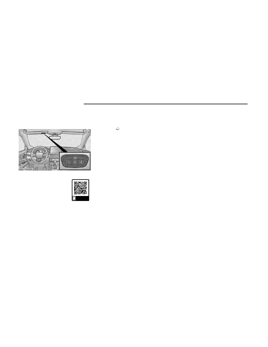
Universal Garage Door Opener
(HomeLink®) — If Equipped

Use this QR code to access your digital
experience.

HomeLink® replaces up to three
hand-held transmitters that operate
devices such as garage door open-
ers, motorized gates, lighting, or
home security systems. The HomeLink® unit is pow-
ered by your vehicle’s 12 Volt battery.

The HomeLink® buttons that are located in the
overhead console or sunvisor designate the three
different HomeLink® channels.

To operate HomeLink®, push and release any of the
programmed HomeLink® buttons. These buttons
will activate the devices they are programmed to
with each press of the corresponding HomeLink®
button.

The HomeLink® indicator light is located above the
center button.

NOTE:

HomeLink® is disabled when the Vehicle Security sys-
tem is active

page 259.

BEFORE YOU BEGIN
PROGRAMMING HOMELINK®

For efficient programming and accurate transmission of
the Radio Frequency (RF) signal, it is recommended
that a new battery be placed in the hand-held transmit-
ter of the device that is being programmed to the
HomeLink® system. Make sure your hand-held trans-
mitter is programmed to activate the device you are
trying to program your HomeLink® button to.

Ensure that your vehicle is parked outside of the garage
before you begin programming.

It is recommended that you erase all the channels of
your HomeLink® before you use it for the first time.

ERASING ALL THE HOMELINK®
CHANNELS

To erase the channels, follow this procedure:

1. Place the ignition switch in the ON/RUN position.

2. Push and hold the two outside HomeLink® buttons

(I and III) for up to 20 seconds, or until the
HomeLink® indicator light flashes.

NOTE:

Erasing all channels should only be performed when
programming HomeLink® for the first time. Do not
erase channels when programming additional buttons.

IDENTIFYING WHETHER YOU HAVE
A ROLLING CODE OR NON-ROLLING
CODE DEVICE

Before programming a device to one of your
HomeLink® buttons, you must determine whether the
device has a rolling code or non-rolling code.

Rolling Code Devices

To determine if your device has a rolling code, a good
indicator is its manufacturing date. Typically, devices
manufactured after 1995 have rolling codes. A device
with a rolling code will also have a “LEARN” or “TRAIN”
button located where the antenna is attached to the
device. The button may not be immediately visible when
looking at the device. The name and color of the button
may vary slightly by manufacturer.

NOTE:

The “LEARN” or “TRAIN” button is not the button you
normally use to operate the device.

Non-rolling Code Devices

Most devices manufactured before 1995 will not have a
rolling code. These devices will also not have a “LEARN”
or “TRAIN” button.

PROGRAMMING HOMELINK® TO A
GARAGE DOOR OPENER

To program any of the HomeLink® buttons to activate
your garage door opener motor, proceed as follows:

NOTE:

All HomeLink® buttons are programmed using this pro-
cedure. You do not need to erase all channels when
programming additional buttons.

HomeLink® Buttons On Sun Visor

Scan me

34

GETTING TO KNOW YOUR VEHICLE

1. Place the ignition switch in the ON/RUN position.

2. Place the garage door opener transmitter 1 to

3 inches (3 to 8 cm) away from the HomeLink® but-
ton you wish to program, while keeping the
HomeLink® indicator light in view.

3. Push and hold the HomeLink® button you want to

program while you push and hold the garage door
opener transmitter button you are trying to replicate.

4. Continue to hold both buttons and observe the

HomeLink® indicator light. The HomeLink® indica-
tor light will flash slowly and then rapidly. Once this
happens, release both buttons.

NOTE:

Make sure the garage door opener motor is plugged in
before moving on to the rolling code/non-rolling code
final steps.

Rolling Code Garage Door Opener Final Steps

NOTE:

You have 30 seconds in which to initiate rolling code
final step 2, after completing rolling code final step 1.

1. At the garage door opener motor (in the garage),

locate the “LEARN” or “TRAIN” button. This can usu-
ally be found where the hanging antenna wire is
attached to the garage door opener motor. Firmly
push and release the “LEARN” or “TRAIN” button.

2. Return to the vehicle and push the programmed

HomeLink® button three times (holding the button
for two seconds each time). If the garage door
opener motor operates, programming is complete.

3. Push the programmed HomeLink® button to con-

firm that the garage door opener motor operates. If
the garage door opener motor does not operate,
repeat the final steps for the rolling code procedure.

Non-Rolling Code Garage Door Opener Final Steps

1. Push and hold the programmed HomeLink® button

and observe the HomeLink® indicator light. If the
HomeLink® indicator light stays on constantly, pro-
gramming is complete.

2. Push the programmed HomeLink® button to con-

firm that the garage door opener motor operates. If
the garage door opener motor does not operate,
repeat the steps from the beginning.

WARNING!

Your motorized door or gate will open and close
while you are programming the universal trans-
ceiver. Do not program the transceiver if people or
pets are in the path of the door or gate.

Do not run your vehicle in a closed garage or con-
fined area while programming the transceiver.
Exhaust gas from your vehicle contains carbon
monoxide (CO) which is odorless and colorless.
Carbon monoxide is poisonous when inhaled and
can cause you and others to be severely injured or
killed.

PROGRAMMING HOMELINK® TO A
MISCELLANEOUS DEVICE

The procedure on how to program HomeLink® to a miscel-
laneous device follows the same procedure as program-
ming to a garage door opener

page 133. Be sure to

determine if the device has a rolling code, or non-rolling
code before beginning the programming process.

NOTE:

Canadian Radio Frequency (RF) laws require transmit-
ter signals to time-out (or quit) after several seconds of
transmission, which may not be long enough for
HomeLink® to pick up the signal during programming.
Similar to this Canadian law, some U.S. gate operators
are designed to time-out in the same manner. The pro-
cedure may need to be performed multiple times to
successfully pair the device to your HomeLink®
buttons.

REPROGRAMMING A SINGLE
HOMELINK® BUTTON

To reprogram a single HomeLink® button that has been
previously trained, without erasing all the channels,
proceed as follows. Be sure to determine whether the
new device you want to program the HomeLink® button
to has a rolling code, or non-rolling code.

1. Place the ignition in the ON/RUN position, without

starting the engine.

2. Push and hold the desired HomeLink® button until

the HomeLink® indicator light begins to flash after
20 seconds.

Do not release the button.

3.

Without releasing the button

, proceed with Step 2

in “Programming HomeLink® To A Garage Door
Opener” and follow all remaining steps.

GETTING TO KNOW YOUR VEHICLE

35

2

CANADIAN/GATE OPERATOR
PROGRAMMING

For programming transmitters in Canada/United States
that require the transmitter signals to “time-out” after
several seconds of transmission:

Canadian Radio Frequency (RF) laws require transmit-
ter signals to time-out (or quit) after several seconds of
transmission, which may not be long enough for
HomeLink® to pick up the signal during programming.
Similar to this Canadian law, some U.S. gate operators
are designed to time-out in the same manner.

It may be helpful to unplug the device during the cycling
process to prevent possible overheating of the garage
door or gate motor.

1. Place the ignition in the ON/RUN position.

NOTE:

For vehicles equipped with Keyless Enter ‘n Go™,
place the ignition in the RUN position. Make sure
while programming HomeLink® with the engine on
that your vehicle is outside of your garage, or that
the garage door remains open at all times.

2. Place the hand-held transmitter 1 to 3 inches (3 to

8 cm) away from the HomeLink® button you wish to
program while keeping the HomeLink® indicator
light in view.

3. Continue to push and hold the HomeLink® button

while you push and release (cycle) your hand-held
transmitter every two seconds until HomeLink® has
successfully accepted the frequency signal. The indi-
cator light will flash slowly and then rapidly when
fully trained.

4. Watch for the HomeLink® indicator to change flash

rates. When it changes, it is programmed. It may
take up to 30 seconds or longer in rare cases. The
garage door may open and close while you are
programming.

5. Push and hold the programmed HomeLink® button

and observe the indicator light.

NOTE:

If the indicator light stays on constantly, program-
ming is complete and the garage door/device
should activate when the HomeLink® button is
pushed.

To program the two remaining HomeLink® but-
tons, repeat each step for each remaining but-
ton. DO NOT erase the channels.

If you unplugged the garage door opener/device for
programming, plug it back in at this time.

Reprogramming A Single HomeLink® Button
(Canadian/Gate Operator)

To reprogram a channel that has been previously
trained, follow these steps:

1. Place the ignition in the ON/RUN position.

2. Press and hold the desired HomeLink® button until

the indicator light begins to flash after 20 seconds.
Do not release the button.

3. Without releasing the button, proceed with

“Canadian/Gate Operator Programming” Step 2 and
follow all remaining steps.

SECURITY

It is advised to erase all channels before you sell or turn
in your vehicle.

To do this, push and hold the two outside buttons for
20 seconds until the indicator flashes. Note that all
channels will be erased. Individual channels cannot be
erased.

The HomeLink® universal transmitter is disabled when
the Vehicle Security system is active.

TROUBLESHOOTING TIPS

If you are having trouble programming HomeLink®,
here are some of the most common solutions:

Replace the battery in the garage door opener hand-
held transmitter.

Push the LEARN button on the garage door opener
to complete the training for a rolling code.

Did you unplug the device for programming and
remember to plug it back in?

If you have any problems, or require assistance, please
call toll-free 1-800-355-3515 or on the Internet at
HomeLink.com for information or assistance.

WARNING!

Vehicle exhaust contains carbon monoxide, a dan-
gerous gas. Do not run your vehicle in the garage
while programming the transmitter. Exhaust gas
can cause serious injury or death.

Your motorized door or gate will open and close
while you are programming the universal transmit-
ter. Do not program the transmitter if people, pets
or other objects are in the path of the door or gate.

(Continued)

36

GETTING TO KNOW YOUR VEHICLE

WARNING!

Only use this transmitter with a garage door
opener that has a “stop and reverse” feature as
required by Federal safety standards. This includes
most garage door opener models manufactured
after 1982. Do not use a garage door opener with-
out these safety features.

EXTERIOR LIGHTS

MULTIFUNCTION LEVER

The multifunction lever controls the operation of the
turn signals, headlight beam selection and passing
lights. The multifunction lever is located on the left side
of the steering column.

HEADLIGHT SWITCH

The headlight switch is located on the left side of the
instrument panel. This switch controls the operation of
the headlights, parking lights, automatic headlights
(if equipped), instrument panel lights, interior lights,
and fog lights (if equipped).

NOTE:

Vehicles sold in Canada are equipped with a headlight
switch with an AUTO and ON detent but without an OFF
detent. Headlights will be deactivated when the head-
light switch is placed in the parking lights position. How-
ever, the Daytime Running Lights (DRLs) will be acti-
vated along with the front and rear marker lights. The
DRLs may be deactivated when the parking brake is
engaged.

Rotate the headlight switch clockwise to the first detent
for parking lights and instrument panel lights operation.
Rotate the headlight switch to the second detent for
headlights, parking lights and instrument panel lights
operation.

NOTE:

For vehicles sold in Canada, rotate the headlight switch
clockwise from the parking lights and instrument panel
lights position to the first detent for headlights, parking
lights and instrument panel lights operation. Rotate the
headlight switch to the second detent for the AUTO
position.

DAYTIME RUNNING LIGHTS (DRLS)
— IF EQUIPPED

The Daytime Running Lights will turn on when the
engine is started and remain on unless the headlamps
are turned on or the ignition is placed in the OFF
position.

NOTE:

For vehicles sold in Canada, the Daytime Running
Lights will automatically deactivate when the front
fog lights are turned on.

Multifunction Lever

Headlight Switch

1 — Rotate Headlight Control
2 — Front Fog Light Switch
3 — Ambient Lighting Control (If Equipped)
4 — Instrument Panel Dimmer Control

Headlight Switch (Vehicles Sold In Canada Only)

1 — Rotate Headlight Control
2 — Front Fog Light Switch
3 — Ambient Lighting Control (If Equipped)
4 — Instrument Panel Dimmer Control

GETTING TO KNOW YOUR VEHICLE

37

2

On some vehicles, the Daytime Running Lights may
deactivate or reduce intensity on one side of the
vehicle (when a turn signal is activated on that
side), or on both sides of the vehicle (when the haz-
ard warning lights are activated).

HIGH/LOW BEAM SWITCH

Push the multifunction lever toward the instrument
panel to switch the headlights to high beams. Pulling
the multifunction lever back will turn the low beams on.

AUTOMATIC HIGH BEAM
HEADLAMP CONTROL —
IF EQUIPPED

The Automatic High Beam Headlamp Control system
provides increased forward lighting at night by automat-
ing high beam control through the use of a digital cam-
era mounted on the windshield. This camera detects
vehicle specific light and automatically switches from
high beams to low beams until the approaching vehicle
is out of view.

NOTE:

The Automatic High Beam Headlamp Control can be
turned on or off through Uconnect Settings

page 133.

Broken, muddy, or obstructed headlights and tail-
lights of vehicles in the field of view will cause head-
lights to remain on longer (closer to the vehicle).
Also, dirt, film, and other obstructions on the wind-
shield or camera lens will cause the system to func-
tion improperly.

FLASH-TO-PASS

You can signal another vehicle with your headlights by
lightly pulling the multifunction lever toward you. This
will cause the high beam headlights to turn on, and
remain on, until the lever is released.

AUTOMATIC HEADLIGHTS —
IF EQUIPPED

This system automatically turns the headlights on or off
according to ambient light levels. To turn the system on,
rotate the headlight switch clockwise to the last detent
for automatic headlight operation. When the system is
on, the headlight time delay feature is also on. This
means the headlights will stay on for up to 90 seconds
after you place the ignition into the OFF position. To
turn the automatic system off, move the headlight
switch out of the AUTO position.

NOTE:

The engine must be running before the headlights will
come on in the automatic mode.

HEADLIGHT TIME DELAY

To assist when exiting the vehicle, the headlight delay
feature will leave the headlights on for up to
90 seconds.

To activate the delay feature, place the ignition in the
OFF position while the headlights are still on. Then, turn
off the headlights within 45 seconds. The delay interval
begins when the headlight switch is turned off.

Headlight delay can be cancelled by either turning the
headlights or parking lights on, or placing the ignition in
the ON/RUN position.

If you turn the headlights off before the ignition, they
will turn off in the normal manner.

NOTE:

The lights must be turned off within 45 seconds of
placing the ignition in the OFF position to activate
this feature. If the headlight switch is in the AUTO
position prior to placing the ignition in the OFF posi-
tion, there is no need to turn the headlight switch to
off to activate Headlight Delay.

The headlight delay timing is programmable through
Uconnect Settings

page 133.

LIGHTS-ON REMINDER

If the headlights or parking lights are on after the igni-
tion is in the OFF position, a chime will sound to alert
the driver when the driver's door is opened.

FOG LIGHTS — IF EQUIPPED

The front fog light switch is built into the headlight
switch.

Fog Light Switch

38

GETTING TO KNOW YOUR VEHICLE

To activate the front fog lights, turn on the parking lights
or the low beam headlights and push the fog light but-
ton. To turn off the front fog lights, either push the fog
lights button a second time or turn off the headlight
switch.

An indicator light in the instrument cluster illuminates
when the fog lights are turned on.

NOTE:

The fog lights will operate with the low beam headlights
or parking lights on. However, selecting the high beam
headlights will turn off the fog lights.

Cornering Lights

The cornering lights are a feature to improve visibility at
night while turning the vehicle. When activated, a light
incorporated in the front fog light will illuminate on the
side of the vehicle the steering wheel is rotated or the
turn signal indicator is on. It can be activated through
the Uconnect system

page 133.

TURN SIGNALS

Move the multifunction lever up or down to activate the
turn signals. The arrows on each side of the instrument
cluster display flash to show proper operation.

NOTE:

If either light remains on and does not flash, or
there is a very fast flash rate, check for a defective
outside light bulb.

A “Turn Signal On” message will appear in the
instrument cluster display and a continuous chime
will sound if the vehicle is driven more than 1 mile
(1.6 km) with either turn signal on.

LANE CHANGE ASSIST

Lightly push the multifunction lever up or down, without
moving beyond the detent, and the turn signal will flash
five times then automatically turn off.

BATTERY SAVER FEATURE

To protect the battery, the interior lights will turn off
automatically 15 minutes after the ignition switch is
placed in the OFF position. This will occur if the interior
lights were switched on manually or are on because a
door is open.

INTERIOR LIGHTS

INTERIOR COURTESY LIGHTS

Courtesy and dome lights are turned on when the front
doors are opened, or when the dimmer control is
rotated to its farthest upward position.

The front map/reading lights are turned on by the
switches in the center of the overhead console.

To protect the battery, the interior lights will turn off
automatically 15 minutes after the ignition is placed in
the OFF position. This will occur if the interior lights
were turned on manually or are on because a door is
open. This includes the glove compartment light and
the cargo area light. To restore interior light operation,
either place the ignition in the ON/RUN position, or
push the light switch on and then back off.

Instrument Panel Dimmer Control

The instrument panel dimmer control is part of the
headlight switch and is located on the driver’s side of
the instrument panel.

Rotating the instrument panel dimmer up or down will
adjust the brightness of the instrument panel lights

ONLY

when the parking lights or headlights are turned

on,

AND ONLY

if the built in light sensor determines

that the ambient light levels are low enough that the
backlighting should be enabled.

Fog Light Switch (Vehicles Sold In Canada Only)

Overhead Light Switches

GETTING TO KNOW YOUR VEHICLE

39

2

Ambient Light Control — If Equipped

Rotate the ambient dimmer control upward or down-
ward to increase or decrease the brightness of the
ambient light located in the overhead console, door
handle lights, lights under the instrument panel, door
map pocket lights, and cubby bin lights.

Ambient lights are only enabled when the headlights
are active.

Illuminated Entry — If Equipped

The Illuminated Entry feature allows you to activate the
low beam, parking lights, and side marker lights for
25 seconds when the vehicle is unlocked (through the
key fob or the Passive Entry door handles [if equipped]).

This feature can be activated or deactivated through
the Uconnect Settings

page 133.

NOTE:

When a door is open with the feature active, the
activation of the lights is extended for five seconds.

The feature is disabled when the vehicle is locked or
when the ignition is placed in the ON/RUN position.

WINDSHIELD WIPERS AND WASHERS

The windshield wiper/washer controls are located on
the windshield wiper/washer lever on the right side of
the steering column. The front wipers are operated by
rotating a switch, located on the end of the lever. For
information on the rear wiper/washer, see

page 42.

WINDSHIELD WIPER OPERATION

Rotate the end of the lever to one of the first two detent
positions for intermittent settings. The first intermittent
wiper interval is 10 seconds. The second intermittent
wipe interval is based on vehicle speed. Rotate to the
third detent for low wiper operation and the fourth
detent for high wiper operation.

Instrument Panel Dimmer

Instrument Panel Dimmer (Vehicles Sold In Canada Only)

Ambient Light Dimmer

Ambient Light Dimmer (Vehicles Sold In Canada Only)

40

GETTING TO KNOW YOUR VEHICLE

CAUTION!

Always remove any buildup of snow that prevents the
windshield wiper blades from returning to the parked
position. If the windshield wiper switch is turned off,
and the blades cannot return to the parked position,
damage to the wiper motor may occur.

Windshield Washer Operation

To use the washer, pull the lever toward you and hold
while spray is desired. If the lever is pulled while in the
intermittent setting, the wipers will turn on and operate
for several wipe cycles after the lever is released, and
then resume the intermittent interval previously selected.

If the lever is pulled while the wipers are in the off posi-
tion, the wipers will operate for several wipe cycles,
then turn off.

NOTE:

As a protective measure, the pump will stop if the
switch is held for more than 20 to 30 seconds. Once
the lever is released the pump will resume normal
operation.

WARNING!

Sudden loss of visibility through the windshield could
lead to a collision. You might not see other vehicles or
other obstacles. To avoid sudden icing of the wind-
shield during freezing weather, warm the windshield
with the defroster before and during windshield
washer use.

Mist

Push the lever upward to the MIST position and release
for a single wiping cycle.

NOTE:

The mist feature does not activate the washer pump;
therefore, no washer fluid will be sprayed on the wind-
shield. The washer function must be used in order to
spray the windshield with washer fluid.

For information on wiper care and replacement, see

page 216.

RAIN SENSING WIPERS —
IF EQUIPPED

This feature senses rain or snow fall on the windshield
and automatically activates the wipers. Rotate the end
of the multifunction lever to one of two detent positions
to activate this feature.

The sensitivity of the system can be adjusted with the
multifunction lever. Wiper delay position one is the least
sensitive, and wiper delay position two is the most sen-
sitive. Place the wiper switch in the O (off) position
when not using the system.

NOTE:

The Rain Sensing feature will not operate when the
wiper switch is in the low or high-speed position.

The Rain Sensing feature may not function properly
when ice, or dried salt water is present on the
windshield.

Use of products containing wax or silicone may
reduce Rain Sensing performance.

The Rain Sensing feature can be turned on and off
through Uconnect Settings

page 133.

The Rain Sensing system has protection features for
the wiper blades and arms, and will not operate under
the following conditions:

Change In Ignition Position

— If the vehicle is in

Rain Sensing mode and the ignition is cycled from
OFF to ON, the auto wiper will be suppressed until
vehicle speed is greater than 3 mph (5 km/h), or the
wiper switch is moved out of and back into the Inter-
mittent wipe position.

Transmission In NEUTRAL Position

— The Rain

Sensing system will not operate if the NEUTRAL gear
is selected at speeds of 3 mph (5 km/h) or less
unless the wiper switch is moved or the gear selec-
tor is moved out of NEUTRAL.

Remote Start Mode Inhibit

— On vehicles equipped

with the Remote Start system, Rain Sensing wipers
are not operational when the vehicle is in Remote
Start mode. Once the operator is in the vehicle and
has placed the ignition switch in the ON/RUN

Windshield Wiper Operation

1 — Push Lever Forward & Hold For Rear Washer
2 — Rotate For Rear Wiper Operation
3 — Rotate For Front Wiper Operation
4 — Pull Lever & Hold For Front Washer Operation
5 — Push Lever Upward For Mist

GETTING TO KNOW YOUR VEHICLE

41

2

position, Rain Sensing wiper operation can resume,
if it has been selected, and no other inhibit condi-
tions (mentioned previously) exist.

REAR WINDOW WIPER/WASHER

The rear wiper/washer controls are located on the
windshield wiper/washer lever on the right side of the
steering column. The rear wiper/washer is operated by
rotating a switch, located at the middle of the lever.

The rear wiper/washer controls are located on the
windshield wiper/washer lever on the right side of the
steering column. The rear wiper has different operation
modes:

Intermittent mode

Synchronous mode (at half speed of the front win-
dow wipers) when the front window wipers are
operating

Continuous mode

Vehicle in REVERSE: If the front wipers are active
and the REVERSE gear is selected, the wiper will
turn on for one wipe

Rotate the center portion of the lever upward
to the first detent for intermittent operation
and to the second detent for continuous rear
wiper operation.

To use the washer, push the lever forward
and hold while spray is desired. If the lever is
pushed while the wiper is in the off position,
the wiper will operate for several wipe cycles,

then turn off.

If the lever is pushed while in the intermittent setting,
the wiper will turn on and operate for several wipe
cycles after the end of the lever is released, and then
resume the intermittent interval previously selected.

NOTE:

As a protective measure, the pump will stop if the
switch is held for more than 20 to 30 seconds. Once
the lever is released the pump will resume normal
operation.

WINDSHIELD WIPER DE-ICER —
IF EQUIPPED

Your vehicle may be equipped with a Windshield Wiper
De-Icer feature that may be activated under the follow-
ing conditions:

Activation By Front Defrost

— The Windshield Wiper

De-Icer shall be activated automatically in the case
of a cold weather manual start with full front
defrost, and when the ambient temperature is
below 33°F (0.6°C).

Activation By Rear Defrost

— The Windshield Wiper

De-Icer shall be activated automatically when the
rear defrost is turned on and when the ambient tem-
perature is below 33°F (0.6°C).

Activation By Remote Start Operation (If Equipped)

— When Remote Start is active and the outside
ambient temperature is less than 33°F (0.6°C), the
Windshield Wiper De-Icer will be enabled. Exiting
Remote Start will resume its previous operation. If
the Windshield Wiper De-Icer was active, the timer
and operation will continue.

CLIMATE CONTROLS

The Climate Control system allows you to regulate the
temperature, air flow, and direction of air circulating
throughout the vehicle. The controls are located on the
touchscreen and on the instrument panel below the
radio.

AUTOMATIC CLIMATE CONTROL
DESCRIPTIONS AND FUNCTIONS

MAX A/C Button

Press and release the MAX A/C button on
the touchscreen to change the current set-
ting to the coldest output of air. The MAX A/C
indicator illuminates when MAX A/C is on.

Pressing the button again will cause the MAX A/C
operation to exit. Pressing other settings will cause the
MAX A/C to exit.

NOTE:

The MAX A/C button is only available on the
touchscreen.

Uconnect 5 With 10.1-inch Display Automatic Climate

Controls

42

GETTING TO KNOW YOUR VEHICLE

A/C Button

Press and release the A/C button on the
touchscreen, or push the button on the face-
plate to change the current setting. The A/C
indicator illuminates when A/C is ON.

The Air Conditioning (A/C) button allows the operator to
manually activate or deactivate the air conditioning sys-
tem. When the air conditioning system is turned on,
dehumidified air will flow through the outlets into the
cabin.

If your air conditioning performance seems lower than
expected, check the front of the A/C condenser (located
in front of the radiator), for an accumulation of dirt or
insects. Clean with a gentle water spray from the front
of the radiator and through the condenser. If the prob-
lem persists, please contact an authorized dealer.

Recirculation Button

Press and release this button on the touch-
screen, or push the button on the faceplate,
to change the system between recirculation
mode and outside air mode. The Recircula-

tion indicator and the A/C indicator illuminate when the
Recirculation button is pressed. Recirculation can be
used when outside conditions such as smoke, odors,
dust, or high humidity are present. Recirculation can be
used in all modes. Recirculation may be unavailable
(button on the touchscreen grayed out) if conditions
exist that could create fogging on the inside of the wind-
shield. The A/C can be deselected manually without
disturbing the mode control selection. Continuous use
of the Recirculation mode may make the inside air
stuffy and window fogging may occur. Extended use of
this mode is not recommended.

NOTE:

After 25 minutes of continuous use, Recirculation
mode will automatically shut off for two minutes to
allow fresh air intake inside the cabin to maintain
sufficient oxygen levels.

Recirculation mode will function in this way, in either
automatic or manual override mode.

AUTO Button

Press and release this button on the touch-
screen, or push the button on the faceplate,
to change the current setting. The AUTO indi-
cator illuminates when AUTO is on. This fea-

ture automatically controls the interior cabin tempera-
ture by adjusting distribution and amount of airflow.
Toggling this function will cause the system to switch
between manual override mode and automatic modes

page 47.

Front Defrost Button

Press and release the touchscreen button,
or push and release the button on the face-
plate, to change the current airflow setting to
Defrost mode. The Front Defrost indicator

illuminates when Front Defrost is on. Air comes from
the windshield and side window demist outlets. When
the defrost button is selected, the blower level may
increase. Use Defrost mode with maximum tempera-
ture settings for the best windshield and side window
defrosting and defogging performance. When toggling
the front defrost mode button, the Climate Control sys-
tem will return to the previous setting.

Rear Defrost Button

Press and release the button on the touch-
screen, or push and release the button on
the faceplate, to turn on the rear window
defroster and the heated outside mirrors

(if equipped). The Rear Defrost indicator illuminates
when the rear window defroster is on. The rear window
defroster automatically turns off after 10 minutes.

CAUTION!

Failure to follow these cautions can cause damage to
the heating elements:

Use care when washing the inside of the rear win-
dow. Do not use abrasive window cleaners on the
interior surface of the window. Use a soft cloth and
a mild washing solution, wiping parallel to the
heating elements. Labels can be peeled off after
soaking with warm water.

Do not use scrapers, sharp instruments, or abra-
sive window cleaners on the interior surface of the
window.

Keep all objects a safe distance from the window.

Driver And Passenger Temperature

Control Buttons

These buttons provide the driver and passenger with
independent temperature control.

Push the red button on the faceplate or touch-
screen or press and slide the temperature bar
towards the red arrow button on the touch-
screen for warmer temperature settings.

GETTING TO KNOW YOUR VEHICLE

43

2

Push the blue button on the faceplate or
touchscreen or press and slide the tempera-
ture bar towards the blue arrow button on
the touchscreen for cooler temperature

settings.

SYNC Button

Press the SYNC button on the touchscreen
to toggle the Sync feature on/off. The SYNC
indicator is illuminated when SYNC is on.
SYNC is used to synchronize the passenger

temperature setting with the driver temperature setting.
Changing the passenger temperature setting while in
SYNC will automatically exit this feature.

NOTE:

The SYNC button is only available on the touchscreen.

Blower Control

Blower Control is used to regulate the
amount of air forced through the Climate
Control system. There are seven blower
speeds available. Adjusting the blower will

cause automatic mode to switch to manual operation.
The speeds can be selected using either the blower
control knob on the faceplate or the buttons on the
touchscreen.

Faceplate

The blower speed increases as you turn the blower con-
trol knob clockwise from the lowest blower setting. The
blower speed decreases as you turn the blower control
knob counterclockwise.

Touchscreen

Use the small blower icon to reduce the blower setting
and the large blower icon to increase the blower set-
ting. Blower can also be selected by pressing the blower
bar area between the icons.

Mode Control

Mode Control regulates the airflow distribu-
tion. The airflow distribution outlets are:
instrument panel outlets, floor outlets,
defrost outlets, and demist outlets.

Faceplate

Push the Mode button to change the airflow distribution
mode.

Touchscreen

Press one of the MODE buttons to change the airflow
distribution mode.

Panel Mode

Air comes from the outlets in the instrument
panel. Each of these outlets can be individu-
ally adjusted to direct the flow of air. The air
vanes of the center outlets and outboard

outlets can be moved up and down or side to side to
regulate airflow direction. There is a shut-off wheel
located below the air vanes to shut off or adjust the
amount of airflow from these outlets.

Bi-Level Mode

Air comes from the instrument panel outlets
and floor outlets. A slight amount of air is
directed through the defrost and side win-
dow demister outlets.

NOTE:

Bi-Level mode is designed under comfort conditions to
provide cooler air out of the panel outlets and warmer
air from the floor outlets.

Floor Mode

Air comes from the floor outlets. A slight
amount of air is directed through the defrost,
side window demister outlets, and panel
outboard outlets.

Defrost Mode

Air comes from the windshield and side win-
dow demist outlets. When the defrost button
is selected, the blower level may increase.
Use Defrost mode with maximum tempera-

ture settings for best windshield and side window
defrosting and defogging. When toggling the front
defrost mode button, the Climate Control system will
return to the previous setting.

Mix Mode

Air is directed through the floor, defrost, and
side window demister outlets. This setting
works best in cold or snowy conditions that
require extra heat to the windshield. This

setting is ideal for maintaining comfort while reducing
moisture on the windshield. A slight amount of air is
also directed through the panel outboard outlets.

Climate Control OFF Button

Press and release the OFF button on the
touchscreen, or push and release the OFF
button on the faceplate to turn the Climate
Control ON/OFF.

44

GETTING TO KNOW YOUR VEHICLE

MANUAL CLIMATE CONTROL
DESCRIPTIONS AND FUNCTIONS

MAX A/C Setting

Press and release the MAX A/C button on
the touchscreen to change the current set-
ting to the coldest output of air. The MAX A/C
indicator illuminates when MAX A/C is on.

Pressing the button again will cause the MAX A/C
operation to exit. Pressing other settings will cause the
MAX A/C to exit.

NOTE:

The MAX A/C button is only available on the
touchscreen.

A/C Button

Push the A/C button to engage the Air Condi-
tioning (A/C). The A/C indicator illuminates
when A/C is on.

NOTE:

For Manual Climate Controls, if the system is in Mix,
Floor or Defrost Mode, the A/C can be turned off,
but the A/C system shall remain active to prevent
fogging of the windows.

If fog or mist appears on the windshield or side
glass, select Defrost mode, and increase blower
speed if needed.

If your air conditioning performance seems lower
than expected, check the front of the A/C condenser
(located in front of the radiator), for an accumula-
tion of dirt or insects. Clean with a gentle water
spray from the front of the radiator and through the
condenser.

Recirculation Button

Push the Recirculation button to change the
system between recirculation mode and out-
side air mode. The Recirculation indicator and
the A/C indicator illuminate when the Recircu-

lation button is pressed. Recirculation can be used when
outside conditions, such as smoke, odors, dust, or
humidity are present. Recirculation can be used in all
modes except for Defrost. Recirculation may be unavail-
able if conditions exist that could create fogging on the
inside of the windshield. The A/C can be deselected
manually without disturbing the mode control selection.
Continuous use of the Recirculation mode may make the
inside air stuffy and window fogging may occur. Extended
use of this mode is not recommended.

On systems with Manual Climate Controls, if equipped,
the Recirculation mode is not allowed in Defrost mode
to improve window clearing operation. Recirculation is
disabled automatically if this mode is selected. Attempt-
ing to use Recirculation while in this mode causes the
LED in the control button to blink and then turns off.

Front Defrost Setting

Press and release the touchscreen button,
or push and release the button on the face-
plate, to change the current airflow setting to
Defrost mode. The Front Defrost indicator

illuminates when Front Defrost is on. Air comes from
the windshield and side window demist outlets. When
the defrost button is selected, the blower level may
increase. Use Defrost mode with maximum tempera-
ture settings for best windshield and side window
defrosting and defogging. When toggling the front
defrost mode button, the Climate Control system will
return to the previous setting.

Rear Defrost Button

Press and release the button on the touch-
screen, or push and release the button on
the faceplate, to turn on the rear window
defroster and the heated outside mirrors

(if equipped). The Rear Defrost indicator illuminates
when the rear window defroster is on. The rear window
defroster automatically turns off after 10 minutes.

CAUTION!

Failure to follow these cautions can cause damage to
the heating elements:

Use care when washing the inside of the rear win-
dow. Do not use abrasive window cleaners on the
interior surface of the window. Use a soft cloth and
a mild washing solution, wiping parallel to the
heating elements. Labels can be peeled off after
soaking with warm water.

(Continued)

Uconnect 5 With 10.1-inch Display Manual Climate

Controls

GETTING TO KNOW YOUR VEHICLE

45

2

CAUTION!

Do not use scrapers, sharp instruments, or abra-
sive window cleaners on the interior surface of the
window.

Keep all objects a safe distance from the window.

Temperature Control

Temperature Control regulates the temperature of the
air forced through the climate system.

Push the red button on the faceplate, or
touchscreen, or press and slide the tempera-
ture bar towards the red arrow button on the
touchscreen for warmer temperature

settings.

Push the blue button on the faceplate, or
touchscreen, or press and slide the tempera-
ture bar towards the blue arrow button on
the touchscreen for cooler temperature

settings.

Blower Control

Blower Control regulates the amount of air
forced through the Climate Control system.
There are seven blower speeds available.
Adjusting the blower will cause automatic

mode to switch to manual operation. The speeds can
be selected using either the blower control knob on the
faceplate or the buttons on the touchscreen.

Faceplate

The blower speed increases as you turn the blower con-
trol knob clockwise from the lowest blower setting. The
blower speed decreases as you turn the blower control
knob counterclockwise.

Touchscreen

Use the small blower icon to reduce the blower setting
and the large blower icon to increase the blower set-
ting. Blower can also be selected by pressing the blower
bar area between the icons.

Mode Control

Push the Mode Control button to change the
airflow distribution mode. The airflow distri-
bution mode can be adjusted so air comes
from the instrument panel outlets, floor out-

lets, defrost outlets, and demist outlets.

Panel Mode

Air comes from the outlets in the instrument
panel. Each of these outlets can be individu-
ally adjusted to direct the flow of air. The air
vanes of the center outlets and outboard

outlets can be moved up and down or side to side to
regulate airflow direction. There is a shut-off wheel
located below the air vanes to shut off or adjust the
amount of airflow from these outlets.

Bi-Level Mode

Air comes from the instrument panel outlets
and floor outlets. A slight amount of air is
directed through the defrost and side win-
dow demister outlets.

NOTE:

Bi-Level mode is designed under comfort conditions to
provide cooler air out of the panel outlets and warmer
air from the floor outlets.

Floor Mode

Air comes from the floor outlets. A slight
amount of air is directed through the defrost
and side window demister outlets.

Defrost Mode

Air comes from the windshield and side win-
dow demist outlets. When the defrost button
is selected, the blower level may increase.
Use Defrost mode with maximum tempera-

ture settings for best windshield and side window
defrosting and defogging. When toggling the front
defrost mode button, the Climate Control system will
return to the previous setting.

Mix Mode

Air is directed through the floor, defrost, and
side window demister outlets. This setting
works best in cold or snowy conditions that
require extra heat to the windshield. This

setting is ideal for maintaining comfort while reducing
moisture on the windshield.

Climate Control OFF

Press and release this button on the touch-
screen, or push and release the button on
the faceplate to turn the Climate Control
ON/OFF.

46

GETTING TO KNOW YOUR VEHICLE

AUTOMATIC TEMPERATURE
CONTROL (ATC)

Automatic Operation

1. Push the AUTO button on the faceplate, or the AUTO

button on the touchscreen (if equipped) on the Auto-
matic Temperature Control (ATC) Panel.

2. Next, adjust the temperature you would like the sys-

tem to maintain by adjusting the temperature con-
trol buttons. Once the desired temperature is dis-
played, the system will achieve and automatically
maintains that comfort level.

3. When the system is set up for your comfort level, it

is not necessary to change the settings. You experi-
ence the greatest efficiency by simply allowing the
system to function automatically.

NOTE:

It is not necessary to move the temperature settings
for cold or hot vehicles. The system automatically
adjusts the temperature, mode, and blower speed
to provide comfort as quickly as possible.

The temperature can be displayed in US or Metric
units by selecting the US/Metric customer-
programmable feature.

To provide you with maximal comfort in the Automatic
mode during cold start-ups, the blower fan remains on
low until the engine warms up. The blower will increase
in speed and transition into Auto mode.

Manual Operation Override

This system offers a full complement of manual over-
ride features. The AUTO symbol in the front ATC display
will be turned off when the system is being used in the
manual mode.

CLIMATE VOICE COMMANDS

Adjust vehicle temperatures hands-free and keep every-
one comfortable while you keep moving ahead.

Push the VR button on the steering wheel. After the
beep, say one of the following commands:

Set the driver temperature to

70

degrees

Set the passenger temperature to

70

degrees

Did You Know:

Voice Command for Climate may only be

used to adjust the interior temperature of your vehicle.
Voice Command will not work to adjust the heated
seats or steering wheel if equipped.

OPERATING TIPS

Refer to the chart at the end of this section for sug-
gested control settings for various weather conditions.

Summer Operation

The engine cooling system must be protected with a
high-quality antifreeze coolant to provide proper corro-
sion protection and to protect against engine overheat-
ing. OAT coolant (conforming to MS.90032) is
recommended.

Winter Operation

To ensure the best possible heater and defroster perfor-
mance, make sure the engine cooling system is func-
tioning properly and the proper amount, type, and con-
centration of coolant is used. Use of the Air
Recirculation mode during Winter months is not recom-
mended, because it may cause window fogging.

Vacation/Storage

For information on maintaining the Climate Control sys-
tem when the vehicle is being stored for an extended
period of time, see

page 247.

Window Fogging

Vehicle windows tend to fog on the inside in mild, rainy,
and/or humid weather. To clear the windows, select
Defrost or Mix mode and increase the front blower
speed. Do not use the Recirculation mode without A/C
for long periods, as fogging may occur.

Outside Air Intake

Make sure the air intake, located directly in front of the
windshield, is free of obstructions, such as leaves.
Leaves collected in the air intake may reduce airflow,
and if they enter the air distribution box, they could plug
the water drains. In Winter months, make sure the air
intake is clear of ice, slush, and snow.

Cabin Air Filter

The Climate Control system filters out dust and pollen
from the air. Contact an authorized dealer to service
your cabin air filter, and to have it replaced when
needed.

Stop/Start System — If Equipped

While in an Autostop, the Climate Control system may
automatically adjust airflow to maintain cabin comfort.
Customer settings will be maintained upon return to an
engine running condition.

GETTING TO KNOW YOUR VEHICLE

47

2

Windshield Wiper De-Icer — If Equipped

The windshield wiper De-Icer is a heating element
located at the base of the windshield.

It operates automatically once the following conditions
are met:

Activation By Front Defrost

The wiper De-Icer activates automatically during a
cold weather manual start with

full defrost,

and

when the

ambient temperature is below 33°F

(6°C)

.

Activation By Rear Defrost

The wiper De-Icer activates automatically when the
Rear Defrost is operating and the

ambient tempera-

ture is below 33°F (6°C)

.

Activation By Remote Start Operation

When Remote Start is activated and the

outside

ambient temperature is less than 33°F (6°C)

the

windshield wiper De-Icer is activated. Exiting
Remote Start will resume its previous operation. If
the Windshield Wiper De-Icer was active, the timer
and operation will continue.

Operating Tips Chart

WEATHER

CONTROL SETTINGS

Hot Weather

And Vehicle

Interior Is Very

Hot

Set the mode control to

(Panel

Mode),

(MAX A/C) on, and

blower on high. Roll down the win-

dows for a minute to flush out the

hot air. Adjust the controls as

needed to achieve comfort.

Warm

Weather

Turn

(A/C) on and set the mode

control to

(Panel Mode).

WEATHER

CONTROL SETTINGS

Cool Sunny

Operate in

(Bi-Level Mode).

Cool & Humid

Conditions

Set the mode control to

(Mix

Mode) and turn

(A/C) on to

keep windows clear.

Cold Weather

Set the mode control to

(Floor

Mode). If windshield fogging starts to

occur, move the control to

(Mix

Mode).

INTERIOR STORAGE AND EQUIPMENT

STORAGE

Glove Compartment

The glove compartment is located on the passenger
side of the instrument panel.

To open the glove compartment, pull the release
handle.

WARNING!

Do not operate this vehicle with a glove compartment
in the open position. Driving with the glove compart-
ment open may result in injury in a collision.

Console Storage Compartment

To open, pull up on the latch and lift the cover.

The center console has a storage area which can hold
cell phones, PDAs, and other small items. The center
console can slide forward and rearward for comfort.

WARNING!

Do not operate this vehicle with a console compart-
ment lid in the open position. Driving with the console
compartment lid open may result in injury in a
collision.

Glove Compartment

Center Console

48

GETTING TO KNOW YOUR VEHICLE

USB CONTROL

This feature allows an external USB device to be
plugged into one of the USB ports, located in the center
stack of the instrument panel.

Plugging in a smartphone device to a USB port will acti-
vate Android Auto™ or Apple CarPlay® features, if
equipped. For further information, refer to “Android
Auto™” or “Apple CarPlay®” in the Uconnect Radio
Instruction Manual.

NOTE:

Two devices can be plugged in at the same time, and
both ports will provide charging capabilities. Only one
port can transfer data to the system at a time.

For example, if a device is plugged into the Type A USB
port and another device is plugged into the Type C USB
port, a message will appear and allow you to select
which device to use.

Different scenarios are listed below when a non-phone
device is plugged into the smaller and larger USB ports,
and when a phone device is plugged into the smaller
and larger USB ports:

“A new device is now connected. Previous connec-
tion was lost.”

“(Phone Name) now connected. Previous connection
was lost.”

“Another device is in use through the same USB
port. Please disconnect the first device to use the
second device.”

Plugging in a phone or another USB device may cause
the connection to a previous device to be lost.

By using a USB cable to connect an external device:

The device can be played on the vehicle’s sound
system, providing the artist, track title, and album
information on the radio display.

NOTE:

Depending on track configuration, track information
may not be present on the radio display.

The device can be controlled using the radio buttons
to play, and browse the contents of the device.

The audio device battery charges when plugged into
the USB port.

The second row USB ports can be used to charge an
external device.

NOTE:

Charge unsupported devices with the Charge Only USB
ports. If an unsupported device is plugged into a Media
USB port, a message will display on the touchscreen
that the device is not supported by the system.

POWER OUTLETS — IF EQUIPPED

Your vehicle may be equipped with 12 Volt (13 Amp)
power outlets that can be used to power cellular
phones, small electronics and other low powered elec-
trical accessories. The power outlets are labeled with
either a “key” or a “battery” symbol to indicate how the
outlet is powered. Power outlets labeled with a key sym-
bol are powered when the ignition is in the ON/RUN
position, while the outlets labeled with a battery symbol
are connected directly to the battery, and powered at all
times.

Front USB Ports

1 — Type C USB Port
2 — Type A USB Port

Charge Only Rear USB Ports

GETTING TO KNOW YOUR VEHICLE

49

2

NOTE:

All accessories connected to the battery powered out-
lets should be removed or turned off when the vehicle
is not in use to protect the battery against discharge.

CAUTION!

Power outlets are designed for accessory plugs only.
Do not insert any other object in the power outlets as
this will damage the outlet and blow the fuse.
Improper use of the power outlet can cause damage
not covered by your New Vehicle Limited Warranty.

If equipped, the front power outlet is located on the
center stack of the instrument panel.

If equipped, a power outlet is located in the rear cargo
area.

NOTE:

The rear cargo area power outlet can be switched from
ignition-only to constant battery powered all the time.
See an authorized dealer for details.

WARNING!

To avoid serious injury or death:

Only devices designed for use in this type of outlet
should be inserted into any 12 Volt outlet.

Do not touch with wet hands.

Close the lid when not in use and while driving the
vehicle.

If this outlet is mishandled, it may cause an elec-
tric shock and failure.

CAUTION!

Many accessories that can be plugged in draw
power from the vehicle's battery, even when not in
use (i.e., cellular phones, etc.). Eventually, if
plugged in long enough, the vehicle's battery will
discharge sufficiently to degrade battery life
and/or prevent the engine from starting.

Accessories that draw higher power (i.e., coolers,
vacuum cleaners, lights, etc.) will degrade the bat-
tery even more quickly. Only use these intermit-
tently and with greater caution.

After the use of high power draw accessories, or
long periods of the vehicle not being started (with
accessories still plugged in), the vehicle must be
driven a sufficient length of time to allow the gen-
erator to recharge the vehicle's battery.

WIRELESS CHARGING PAD —
IF EQUIPPED

Front Power Outlet

Rear Cargo Area Power Outlet — If Equipped

Wireless Charging Pad

50

GETTING TO KNOW YOUR VEHICLE

Your vehicle may be equipped with a 15W 3A Qi® wire-
less charging pad located below the center stack,
within the storage compartment. This charging pad is
designed to wirelessly charge your Qi® enabled mobile
phone. Qi® is a standard that allows wireless charging
of your mobile phone.

Your mobile phone must be designed for Qi® wireless
charging. If the phone is not equipped with Qi® wireless
charging functionality, an aftermarket sleeve or a spe-
cialized back plate can be purchased from your mobile
phone provider or a local electronics retailer. Please
see your phone’s owner’s manual for further
information.

The wireless charging pad is equipped with an anti-slip
mat to hold your mobile phone in place, and an LED
indicator light.

Place the device inside the prepared area delimited in
the mat as shown in the image. Incorrect positioning
will prevent the phone from charging.

LED Indicator Status:

No Light: Charging pad is idle or searching for a
device. Device may not be compatible with the Qi®
standard.

Blue Light: Device is detected and is charging.

Red Light/Flashing: Internal error, or foreign object
is detected.

Green Light: Device has completed battery charging
(if device is equipped to transmit this information).

Important Notes Regarding This Vehicle’s Wireless
Charging Pad:

The presence of the Near-Field Communication
(NFC) function active on a smartphone could signal
malfunction anomalies.

The ignition must be in the ON/RUN or START posi-
tion in order for the phone to charge.

To avoid interference with the key fob search, the
wireless charging pad will stop charging when any
door or liftgate is opened, even if the engine is
running.

Be sure to place the mobile device correctly (display
facing upward, and phone not covering the LED) on
the wireless charging pad.

If the phone moves on the pad causing the red light
to illuminate, the phone will have to be picked up
and placed back on the charging pad to resume
charging.

Wireless charging is not as fast as when the phone
is connected to a wired charger.

The phone’s protective case must be removed when
placed on the wireless charging pad.

iPhone® 12 (including iPod®) is equipped with soft-
ware to protect the device from overheating. When
the software is active, the rate of charge is slowed
down to protect the device.

Phones must always be placed on the wireless
charging pad within the outline shown on the pad so
that its charging parts connect with the charging
coils of the system. Movement of the phone during
charging may prevent or slow the rate of charge.

Having multiple applications open on the phone
while charging will reduce the charging efficiency,
and may even shut down an application that is
actively running (i.e. Apple CarPlay®). This may also
cause the phone to overheat.

Wireless chargers may implement certain methods
to prevent the phone from overheating during charg-
ing such as slowing down the rate of charge. In cer-
tain instances, the device may shut down for a brief
period of time (when the device reaches a certain
temperature). If this happens, it does not mean
there is a fault with the wireless charging pad. This
may just be a protective measure to prevent dam-
age to the phone.

The use of multiple wireless functions at the same
time (wireless charging, Apply CarPlay®, Android
Auto™) could cause the device to overheat, resulting
in limitation of the functions or it turning off. In this
case, it is recommended to connect the system
using the USB port.

Do not place the key fob or any other type of metal/
magnetized object inside the mobile phone housing
or near the wireless charging pad.

With a compatible device placed on the charging
pad, and the ignition is cycled to the OFF position, a
reminder message may appear on the instrument
cluster display to warn the driver.

CAUTION!

The key fob should not be placed on the charging pad
or within 6 inches (15 cm) of it. Doing so can cause
excessive heat buildup and damage to the fob. Plac-
ing the fob in close proximity of the charging pad
blocks the fob from being detected by the vehicle and
prevents the vehicle from starting.

GETTING TO KNOW YOUR VEHICLE

51

2

WINDOWS

POWER WINDOW CONTROLS

The window controls on the driver's door control all the
door windows.

The passenger door windows can also be operated by
using the single window controls on each passenger
door trim panel. The window controls will operate only
when the ignition is in the ON/RUN position.

To open the window part way, push the window switch
down briefly and release it when you want the window
to stop.

NOTE:

The power window switches will remain active for up to
10 minutes after the ignition is placed in the OFF posi-
tion. Opening either front door will cancel this feature.

The timing is programmable within Uconnect Settings

page 133.

WARNING!

Never leave children unattended in a vehicle. Do not
leave the key fob in or near the vehicle or in a loca-
tion accessible to children, and do not leave the igni-
tion of a vehicle equipped with Keyless Enter ‘n Go™
in the ON/RUN position. Occupants, particularly unat-
tended children, can become entrapped by the win-
dows while operating the power window switches.
Such entrapment may result in serious injury or
death.

AUTOMATIC WINDOW FEATURES

Auto-Down Feature

The driver and front passenger door power window
switches have an Auto-Down feature. Push the window
switch down briefly, then release, and the window will
go down automatically.

To stop the window from going all the way down during
the Auto-Down operation, pull up or push the switch
briefly.

Auto-Up Feature With Anti-Pinch Protection

Lift the window switch up briefly and release; the win-
dow will go up automatically.

To stop the window from going all the way up during the
Auto-Up operation, push down or pull the switch briefly.

To close the window part way, lift the window switch
briefly and release it when you want the window to stop.

If the window runs into any obstacle during auto-
closure, it will reverse direction and then go back down.
Remove the obstacle and use the window switch again
to close the window.

NOTE:

Any impact due to rough road conditions may trigger the
auto-reverse function unexpectedly during auto-closure.
If this happens, pull the switch lightly and hold to close
the window manually.

WARNING!

There is no anti-pinch protection when the window is
almost closed. To avoid personal injury be sure to
clear your arms, hands, fingers and all objects from
the window path before closing.

RESET AUTO-UP

Should the Auto-Up feature stop working, the window
probably needs to be reset. To reset Auto-Up:

1. Pull the window switch up to close the window com-

pletely and continue to hold the switch up for an
additional two seconds after the window is closed.

2. Push the window switch down firmly to open the

window completely and continue to hold the switch
down for an additional two seconds after the win-
dow is fully open.

WINDOW LOCKOUT SWITCH

The window lockout switch on the driver's door trim
panel allows you to disable the window controls on the
rear passenger doors. To disable the window controls,
push and release the window lockout switch (the indica-
tor light on the switch will turn on). To enable the win-
dow controls, push and release the window lockout
switch again (the indicator light on the switch will
turn off).

Power Window Controls

52

GETTING TO KNOW YOUR VEHICLE

WIND BUFFETING

Wind buffeting can be described as the perception of
pressure on the ears or a helicopter-type sound in the
ears. Your vehicle may exhibit wind buffeting with the
windows down, or the sunroof (if equipped) in certain
open or partially open positions. This is a normal occur-
rence and can be minimized. If the buffeting occurs
with the rear windows open, open the front and rear
windows together to minimize the buffeting. If the buf-
feting occurs with the sunroof open, adjust the sunroof
opening to minimize the buffeting or open any window.

POWER SUNROOF WITH POWER SHADE
— IF EQUIPPED

The power sunroof switches are located between the
sun visors on the overhead console.

WARNING!

Never leave children unattended in a vehicle, or
with access to an unlocked vehicle. Never leave
the key fob in or near the vehicle, or in a location
accessible to children. Do not leave the ignition of
a vehicle equipped with Keyless Enter ‘n Go™ in
the ON/RUN position. Occupants, particularly unat-
tended children, can become entrapped by the
power sunroof while operating the power sunroof
switch. Such entrapment may result in serious
injury or death.

In a collision, there is a greater risk of being thrown
from a vehicle with an open sunroof. You could
also be seriously injured or killed. Always fasten
your seat belt properly and make sure all passen-
gers are also properly secured.

(Continued)

WARNING!

Do not allow small children to operate the sunroof.
Never allow your fingers, other body parts, or any
object, to project through the sunroof opening.
Injury may result.

Do not use the sunroof and its related parts for
supporting and/or grabbing purposes. Serious per-
sonal injury may result to fingers and other body
parts as well as damage to the sunroof.

OPENING AND CLOSING THE
SUNROOF

The sunroof has two programmed open positions, com-
fort stop position and full open position. The comfort
stop position has been optimized to minimize wind buf-
feting when driving with side windows closed and sun-
roof open. If the sunshade is in the closed position
when initiating a sunroof open or vent command the
sunshade will automatically open to the half open posi-
tion prior to the sunroof opening.

Express Open/Close

Push the switch to open and release it within one-half
second and the sunroof will open to the comfort stop
(partially opened) position and automatically stop. Push
the switch and release it again, and the sunroof will
open to the full open position then automatically stop.

Pull the switch to close and release it within one-half
second and the sunroof will completely close automati-
cally from any position.

During Express Open or Express Close operation, any
movement of the sunroof switch will stop the sunroof.

Window Lockout Switch

Power Sunroof Switches

1 — Power Shade Switch
2 — Front Panel Open/Close Switch
3 — Front Panel Vent Switch

GETTING TO KNOW YOUR VEHICLE

53

2

Manual Open/Close

Push and hold the switch to open. The sunroof will open
to the comfort stop (partially opened) position and auto-
matically stop. Push the switch and hold it again, and
the sunroof will open to the full open position then
automatically stop.

Pull and hold the switch to completely close the sunroof
from any position.

Any release of the switch during open or close opera-
tion will stop the sunroof movement. The sunroof will
remain in a partially opened position until the switch is
operated and held again.

VENTING SUNROOF

Push and release the vent switch within one-half sec-
ond and the sunroof will move from the closed position
to the vent position. This is called “Express Vent.” Dur-
ing Express Vent operation, any movement of the switch
will stop the sunroof.

NOTE:

When the sunroof is in a full open or a partial open
position, Express Vent operation is not available. You
must push and hold the vent switch to cycle the sunroof
from a slide open position to the vent position. Sunroof
movement will stop if the switch is released prior to the
sunroof reaching the vent position.

OPENING AND CLOSING THE
POWER SUNSHADE

The sunshade has two programmed open positions:
half open and full open. When opening the sunshade
from the closed position, the sunshade will always stop
at the half open position regardless of express or
manual operation. The switch must be pushed again to
continue on to full open position.

Express Open/Close

Push the sunshade switch to open and release it within
one-half second and the sunshade will open to the half
open position and stop automatically. Push the switch
and release it again, and the sunshade will open to the
full open position and stop automatically.

Pull the sunshade switch to close and release it within
one-half second. If the sunroof is in closed position, the
sunshade will full close automatically from any position.
If the sunroof is open or vented, the sunshade cannot
be closed beyond the half open position. Pulling the
sunshade switch when the sunshade is in the half open
position will automatically close sunroof prior to the
sunshade closing.

During Express Open or Express Close operation, any
movement of the sunshade switch will stop the shade.

Manual Open/Close

Push and hold the sunshade switch to open. The sun-
shade will open to the half open position and stop auto-
matically. Push and hold the switch again, and the sun-
shade will open to the full open position.

Pull and hold the sunshade switch to close. If the sun-
roof is in closed position, the sunshade will fully close
from any position. If the sunroof is open or vented, the
sunshade will close to the half open position and stop.
Pulling and holding the switch again will close both the
sunroof and sunshade completely.

Any release of the switch will stop the movement and
the sunshade will remain in a partially opened position
until the switch is pushed again.

PINCH PROTECT FEATURE

This feature will detect an obstruction in the opening of
the sunroof during Express Close operation. If an
obstruction in the path of the sunroof is detected, the
sunroof will automatically retract. Remove the obstruc-
tion if this occurs. Next, pull the sunroof close switch
and release to Express Close.

NOTE:

If three consecutive sunroof close attempts result in
Pinch Protect reversals, Pinch Protect will disable and
the sunroof must be closed in Manual Mode.

SUNROOF MAINTENANCE

Use only a non-abrasive cleaner and a soft cloth to
clean the glass panel. Periodically check for and clear
out any debris that may have collected in the tracks.

HOOD

OPENING THE HOOD

Two latches must be released to open the hood.
1. Pull the hood release lever located underneath the

driver’s side of the instrument panel.

Hood Release Location (Underneath Instrument Panel)

54

GETTING TO KNOW YOUR VEHICLE

2. Move to the outside of the vehicle. The safety latch

release lever is located behind the front edge of the
hood at the center. Reach in at the center of the
hood with a palm facing the ground. Once contact is
made with the safety latch release lever, push it
toward the passenger side of the vehicle to fully
release the hood.

NOTE:

Vehicle must be at a stop and the gear selector
must be in PARK.

While lifting the hood, use both hands.

Before lifting the hood, check that the wiper arms
are not in motion and not in the lifted position.

CLOSING THE HOOD

Hoods equipped with gas props are closed from the
point where the props no longer hold the hood open.

WARNING!

Be sure the hood is fully latched before driving your
vehicle. If the hood is not fully latched, it could open
when the vehicle is in motion and block your vision.
Failure to follow this warning could result in serious
injury or death.

CAUTION!

To prevent possible damage, do not slam the hood to
close it. Lower hood to approximately 12 inches
(30 cm) and drop the hood to close. Make sure hood
is fully closed for both latches. Never drive vehicle
unless hood is fully closed, with both latches
engaged.

LIFTGATE

UNLOCK/OPEN THE LIFTGATE

The liftgate may be released in one of several ways:

Key fob (if equipped with power liftgate)

Outside handle

Button on overhead console (if equipped with power
liftgate)

Hands-Free Liftgate (if equipped)

The overhead console switch and key fob (if equipped)
will release the liftgate when the liftgate is unlocked or
locked. The outside handle requires the liftgate to be
unlocked.

To Unlock The Liftgate

Use the key fob or the interior door unlock button on
the door panel to unlock the liftgate. The manual door
locks on the doors will not unlock the liftgate.

WARNING!

Driving with the liftgate open can allow poisonous
exhaust gases into your vehicle. You and your passen-
gers could be injured by these fumes. Keep the lift-
gate closed when you are operating the vehicle.

LOCK/CLOSE THE LIFTGATE

To manually close the liftgate, grab the liftgate closing
handle and pull in a downward motion to close the
liftgate.

Hood Safety Latch Release Lever Location

Liftgate Entry

GETTING TO KNOW YOUR VEHICLE

55

2

NOTE:

Before closing the liftgate, make sure to be in posses-
sion of the key fob because the liftgate may be locked.

To Lock The Liftgate

Use the key fob or the interior door lock button on the
door panel to lock the liftgate. The manual door locks
on the doors will not lock the liftgate.

POWER LIFTGATE — IF EQUIPPED

The power liftgate may be opened by push-
ing the liftgate button on the key fob. Push
the liftgate button on the key fob twice within
five seconds to open or close the power lift-

gate. You can also open the liftgate by pushing the elec-
tronic liftgate release handle

page 21.

Using any of the following ways:

When the liftgate is fully closed, the liftgate will
open.

When the liftgate is fully open, the liftgate will close.

When the liftgate is moving, the liftgate will reverse.

The power liftgate may also be opened or closed by
pushing the liftgate button located on the front over-
head console. If the liftgate is fully open, the liftgate
can be closed by pushing the liftgate button located on
the left rear trim panel. If the liftgate is in motion, push-
ing the button again will reverse the liftgate.

When the liftgate button on the key fob is pushed two
times, the turn signals will flash twice to signal that the
liftgate is opening or closing, and an audible chime can
be heard (if enabled in the Uconnect Settings

page 133).

The key fob and the overhead console switch will open
the liftgate when the liftgate is locked. The outside
handle requires the liftgate to be unlocked. If the
vehicle is equipped with Passive Entry, and a valid Pas-
sive Entry key fob is within 5 ft (1.5 m) of the liftgate,
pulling the outside handle will unlock and open the
liftgate.

NOTE:

Before closing the liftgate, make sure to be in pos-
session of the key fob because the liftgate may be
locked.

Use the interior door lock/unlock button on the door
panel or the key fob to lock and unlock the liftgate.
The manual door locks on the doors and the exterior
door lock cylinder will not lock and unlock the liftgate.

The liftgate will either unlock along with the vehicle
doors, or it will need to be unlocked by pushing the
electronic liftgate release, depending on the
selected setting in the Uconnect system

page 133.

The power liftgate buttons will not operate if the
vehicle is in gear or the vehicle speed is above
0 mph (0 km/h).

The power liftgate will not operate in temperatures
below −22°F (−30°C) or temperatures above
150°F (65°C). Be sure to remove any buildup of
snow or ice from the liftgate before pushing any of
the power liftgate switches.

If anything obstructs the power liftgate while it is
closing or opening, the liftgate will automatically
reverse to the closed or open position. After multiple
obstructions in the same cycle, the liftgate will auto-
matically stop and must be opened or closed
manually.

There are pinch sensors attached to the side of the
liftgate. Light pressure anywhere along these strips
will cause the liftgate to return to the open position.

The power liftgate must be in the full open position
in order for the rear liftgate close button, on the left
rear trim near the liftgate opening, to operate. If the
liftgate is not fully open, push the liftgate button on
the key fob to fully open the liftgate and then push it
again to close.

If the electronic liftgate release handle is pushed a
second time while the power liftgate is opening, the
liftgate motor will disengage to allow manual
operation.

If your liftgate is power closing and you put the
vehicle in gear, the liftgate will continue to power
close. However, vehicle movement may result in the
detection of an obstruction.

Allow the power system to open the liftgate. Manu-
ally pushing or pulling the liftgate may activate the
liftgate obstacle detection feature and stop the
power operation or reverse its direction.

Liftgate Pull Handle/Closing Liftgate

56

GETTING TO KNOW YOUR VEHICLE

WARNING!

Driving with the liftgate open can allow poisonous
exhaust gases into your vehicle. You and your pas-
sengers could be injured by these fumes. Keep the
liftgate closed when you are operating the vehicle.

If you are required to drive with the liftgate open,
make sure that all windows are closed, and the
climate control blower switch is set at high speed.
Do not use the recirculation mode.

During power operation, personal injury or cargo
damage may occur. Ensure the liftgate travel path
is clear. Make sure the liftgate is closed and
latched before driving away.

Personal injury or cargo damage may occur if
caught in the path of the liftgate. Make sure the
liftgate path is clear before activating the liftgate.

HANDS-FREE LIFTGATE —
IF EQUIPPED

To open or close the liftgate using hands-free activa-
tion, use a straight in and out kicking motion under the
vehicle activation zone in the general location below
the rear license plate. The activation zone is about
1.8 ft (0.5 m) from side to side. Do not move your foot
sideways or in a sweeping motion or the sensors may
not detect the motion.

NOTE:

Activation zone is the same for vehicles equipped with
or without a trailer tow package.

When a valid kicking motion is completed, the liftgate
will chime, the hazard lights will flash and the liftgate
will open after approximately one second, or close after
approximately three seconds. These settings can be
enabled or disabled through Uconnect Settings

page 133.

NOTE:

Opening or closing the Hands-Free Liftgate requires
a valid Passive Entry key fob within 5 ft (1.5 m) of
the door handle. If a valid Passive Entry key fob is
not within 5 ft (1.5 m), the liftgate will not respond
to any kicks.

The Hands-Free Liftgate feature may be turned on or
off through the Uconnect system

page 133.

The Hands-Free Liftgate feature should be turned
off during jacking, tire changing, manual car wash,
and vehicle service.

The Hands-Free Liftgate feature can be activated by
any metallic object making a similar in-and-out
motion under the rear fascia/bumper, such as
cleaning using a metal broom.

The Hands-Free Liftgate will only operate when the
transmission is in PARK.

If anything obstructs the Hands-Free Liftgate while it
is opening or closing, the liftgate will automatically
reverse to the closed/open position, provided it
meets sufficient resistance.

There are pinch sensors attached to the side of the
liftgate opening. Light pressure anywhere along
these strips will cause the liftgate to return to the
open position.

If the power liftgate encounters multiple obstruc-
tions within the same cycle, the system will auto-
matically stop. If this occurs, the liftgate must be
operated manually.

The power liftgate will release, but not power open,
in temperatures below −12°F (−24°C). Be sure to
remove any buildup of snow or ice from the liftgate
before opening the liftgate.

If the liftgate is left open for an extended period of
time (approximately one hour), the liftgate may need
to be closed manually to reset power liftgate
functionality.

WARNING!

Driving with the liftgate open can allow poisonous
exhaust gases into your vehicle. You and your pas-
sengers could be injured by these fumes. Keep the
liftgate closed when you are operating the vehicle.

If you are required to drive with the liftgate open,
make sure that all windows are closed, and the
climate control blower switch is set at high speed.
Do not use the recirculation mode.

During power operation, personal injury or cargo
damage may occur. Ensure the liftgate travel path
is clear. Make sure the liftgate is closed and
latched before driving away.

(Continued)

Hands-Free Liftgate Activation Zone

GETTING TO KNOW YOUR VEHICLE

57

2

WARNING!

Personal injury or cargo damage may occur if
caught in the path of the liftgate. Make sure the
liftgate path is clear before activating the liftgate.

Gas props support the liftgate in the open position.
However, because the gas pressure drops with tem-
perature, it may be necessary to assist the props when
opening the liftgate in cold weather.

NOTE:

Allow the power system to open the liftgate. Manually
pushing or pulling the liftgate may activate the liftgate
obstacle detection feature and stop the power opera-
tion or reverse its direction.

CARGO AREA FEATURES

Cargo Load Floor

The cargo load floor system has a load capacity of
300 lb (136 kg).

Cargo Load Floor Positions

The cargo load floor can be adjusted to three different
levels to create more space in the cargo area. These
positions are: upper, center, and lower.

NOTE:

The lower position is not available in vehicles equipped
with either a compact spare tire, or a full size spare tire.
The center position is not available in vehicles equipped
with a full size spare tire.

To change the level of the load floor, pull upward on the
load floor handle, pull the floor outward, and place the
back of the floor into the desired position. Lower the
front of the floor into place.

Raising The Load Floor

To raise the load floor for access to the Tire Service Kit,
or spare tire (if equipped), pull upward on the load floor
handle.

Do not raise the floor beyond the point of resistance. In
vehicles equipped with a power liftgate, forcing the floor
upward can damage the floor and vehicle’s trim panel.

To fully raise the load floor, pull upward on the floor
handle, pull the floor outward, then position the floor
upright with the bottom fitting on top of the floor posi-
tioning brackets. Push the top of the floor down firmly
to secure it in this position.

Cargo Load Floor Positions

1 — Upper Position
2 — Center Position
3 — Lower Position

Raised Load Floor — (Power Liftgate)

1 — Raised Floor Maximum Height
2 — Raised Load Floor

Fully Raised Load Floor Position

58

GETTING TO KNOW YOUR VEHICLE

To provide additional storage area, each rear seat can
be folded flat. This allows for extended cargo space and
still maintains some rear seating room

page 25.

Cargo Tie-Down Hooks And Loops

The tie-downs located on the cargo area floor should be
used to secure loads safely when the vehicle is moving.

Cargo tie-down loops are located on the trim panels.

WARNING!

Cargo tie-downs are not safe anchors for a child
seat tether strap. In a sudden stop or accident, a
tie-down could pull loose and allow the child seat
to come loose. A child could be badly injured. Use
only the anchors provided for child seat tethers.

To help protect against personal injury, passengers
should not be seated in the rear cargo area. The
rear cargo space is intended for load carrying pur-
poses only, not for passengers, who should sit in
seats and use seat belts.

The weight and position of cargo and passengers can
change the vehicle center of gravity and vehicle han-
dling. To avoid loss of control resulting in personal
injury, follow these guidelines for loading your vehicle:

Do not carry loads that exceed the load limits
described on the label attached to the left door or
left door center pillar.

Always place cargo evenly on the cargo floor. Put
heavier objects as low and as far forward as
possible.

Place as much cargo as possible in front of the
rear axle. Too much weight or improperly placed
weight over or behind the rear axle can cause the
vehicle to sway.

(Continued)

WARNING!

Do not pile luggage or cargo higher than the top of
the seatback. This could impair visibility or become
a dangerous projectile in a sudden stop or
accident.

Rear Storage Bins

The rear storage bins are located in the rear of the
vehicle on the sides of the load floor.

ROOF LUGGAGE RACK — IF EQUIPPED

The load carried on the roof, when equipped with a lug-
gage rack, must not exceed 150 lb (68 kg), and it
should be uniformly distributed over the cargo area.

Crossbars should always be used whenever cargo is
placed on the roof rack. Check the straps frequently to
be sure that the load remains securely attached.

NOTE:

Crossbars can be purchased at your authorized dealer
through Mopar® parts.

External racks do not increase the total load carrying
capacity of the vehicle. Be sure that the total occupant
and luggage load inside the vehicle, plus the load on
the luggage rack, does not exceed the maximum
vehicle load capacity.

WARNING!

Cargo must be securely tied down before driving your
vehicle. Improperly secured loads can fly off the
vehicle, particularly at high speeds, resulting in per-
sonal injury or property damage. Follow the roof rack
cautions when carrying cargo on your roof rack.

Rear Storage Bin

GETTING TO KNOW YOUR VEHICLE

59

2

CAUTION!

To avoid damage to the roof rack and vehicle, do
not exceed the maximum roof rack load capacity.
Always distribute heavy loads as evenly as possible
and secure the load appropriately.

Long loads, which extend over the windshield,
should be secured to both the front and rear of the
vehicle.

Place a blanket or other protection between the
surface of the roof and the load.

Travel at reduced speeds and turn corners care-
fully when carrying large or heavy loads on the roof
rack. Wind forces, due to natural causes or nearby
truck traffic, can add sudden upward lift. It is rec-
ommended to not carry large flat loads, such as
wood panels or surfboards, which may result in
damage to the cargo or your vehicle.

Load should always be secured to crossbars first,
with tie down loops used as additional securing
points if needed. Tie loops are intended as supple-
mentary tie down points only. Do not use ratchet-
ing mechanisms with the tie loops. Check the
straps frequently to be sure that the load remains
securely attached.

60

GETTING TO KNOW YOUR VEHICLE

GETTING TO KNOW YOUR INSTRUMENT PANEL

BASE / MIDLINE INSTRUMENT CLUSTER

61

3

Use this QR code to access your digital
experience.

Scan me

62

GETTING TO KNOW YOUR INSTRUMENT PANEL

BASE / MIDLINE INSTRUMENT
CLUSTER DESCRIPTIONS

1. Tachometer

Indicates the engine speed in revolutions per
minute (RPM x 1000).

2. Instrument Cluster Display

The instrument cluster display features a driver
interactive display

page 65.

3. Speedometer

Indicates vehicle speed.

4. Temperature Gauge

The temperature gauge shows engine coolant
temperature. Any reading within the normal
range indicates that the engine cooling system
is operating satisfactorily.

The gauge pointer will likely indicate a higher
temperature when driving in hot weather or up
mountain grades. It should not be allowed to
exceed the upper limits of the normal operating
range.

WARNING!

A hot engine cooling system is dangerous. You or oth-
ers could be badly burned by steam or boiling cool-
ant. It is recommended to call an authorized dealer
for service if your vehicle overheats

page 219.

CAUTION!

Driving with a hot engine cooling system could dam-
age your vehicle. If the temperature gauge reads “H”,
pull over and stop the vehicle. Idle the vehicle with
the air conditioner turned off until the pointer drops
back into the normal range. If the pointer remains on
the “H”, turn the engine off immediately and call an
authorized dealer for service.

5. Fuel Gauge

The gauge shows the level of fuel in the fuel
tank when the ignition switch is in the ON/RUN
position.

The fuel pump symbol points to the
side of the vehicle where the fuel
door is located.

NOTE:

The hard telltales will illuminate for a bulb check when
the ignition is first cycled.

GETTING TO KNOW YOUR INSTRUMENT PANEL

63

3

PREMIUM INSTRUMENT CLUSTER

64

GETTING TO KNOW YOUR INSTRUMENT PANEL

PREMIUM INSTRUMENT CLUSTER
DESCRIPTIONS

1. Temperature Gauge

The temperature gauge shows engine coolant
temperature. Any reading within the normal
range indicates that the engine cooling system
is operating satisfactorily.

The pointer will likely indicate a higher tempera-
ture when driving in hot weather, up mountain
grades, or when towing a trailer. It should not be
allowed to exceed the upper limits of the normal
operating range.

WARNING!

A hot engine cooling system is dangerous. You or oth-
ers could be badly burned by steam or boiling cool-
ant. It is recommended to call an authorized dealer
for service if your vehicle overheats

page 219.

CAUTION!

Driving with a hot engine cooling system could dam-
age your vehicle. If the temperature gauge reads “H”,
pull over and stop the vehicle. Idle the vehicle with
the air conditioner turned off until the pointer drops
back into the normal range. If the pointer remains on
the “H”, turn the engine off immediately and call an
authorized dealer for service.

2. Tachometer

Indicates the engine speed in revolutions per
minute (RPM x 1000).

3. Speedometer

Indicates vehicle speed.

4. Fuel Gauge

The pointer shows the level of fuel in the fuel
tank when the Keyless Push Button Ignition is in
the ON/RUN position.

The fuel pump symbol points to the
side of the vehicle where the fuel
door is located.

NOTE:

The Instrument Cluster Warning Indicators will illumi-
nate briefly for a bulb check when the ignition is first
cycled.

INSTRUMENT CLUSTER DISPLAY

Your vehicle may be equipped with an instrument clus-
ter display, which offers useful information to the driver.
With the ignition in the OFF mode, opening/closing of a
door will activate the display for viewing, and display the
total miles, or kilometers, in the odometer. Your instru-
ment cluster display is designed to display important
information about your vehicle’s systems and features.
Using the driver interactive display located on the
instrument panel, your instrument cluster display can
show you how systems are working and give you warn-
ings when they aren’t. The steering wheel mounted con-
trols allow you to scroll through and enter the main
menus and submenus. You can access the specific
information you want and make selections and
adjustments.

INSTRUMENT CLUSTER DISPLAY
LOCATION AND CONTROLS

The instrument cluster display features a driver interac-
tive display that is located in the instrument cluster.

NOTE:

Depending on your vehicle trim, your instrument cluster
display may vary.

Instrument Cluster Display Location and Controls

1 – Instrument Cluster Display Screen
2 – Instrument Cluster Display Controls

GETTING TO KNOW YOUR INSTRUMENT PANEL

65

3


Content      ..      1      2      3      ..