Jeep Wrangler (2023 year). Manual in english - page 18
 

  Index      Manuals     Jeep Wrangler (2023 year). Manual in english


Search            copyright infringement  


Content      ..     16      17      18      19     ..


Jeep Wrangler (2023 year). Manual in english - page 18


SAFETY

281

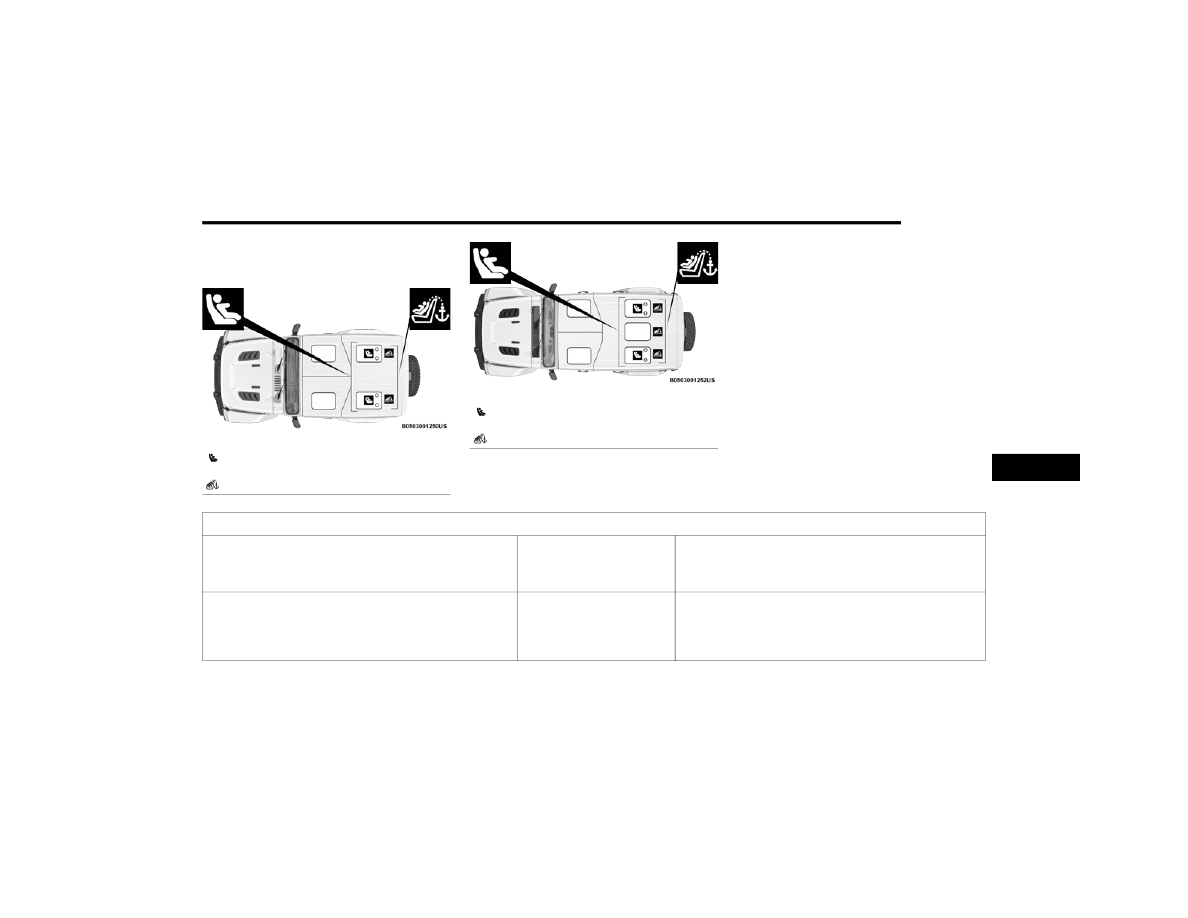
LATCH Positions For Installing Child 

Restraints In This Vehicle

LATCH Positions (Two-Door Models)

LATCH Positions (Four-Door Models)

 Lower Anchorage Symbol

(2 Anchorages Per Seating Position)

 Top Tether Anchorage Symbol

 Lower Anchorage Symbol

(2 Anchorages Per Seating Position)

 Top Tether Anchorage Symbol

Frequently Asked Questions About Installing Child Restraints With LATCH

What is the weight limit (child’s weight + weight of the child restraint) 

for using the LATCH anchorage system to attach the child restraint?

65 lb (29.5 kg)

Use the LATCH anchorage system until the combined weight of the 

child and the child restraint is 65 lb (29.5 kg). Use the seat belt and 

tether anchor instead of the LATCH system once the combined weight 

is more than 65 lb (29.5 kg).

Can the LATCH anchorages and the seat belt be used together to attach 

a rear-facing or forward-facing child restraint?

No

Do not use the seat belt when you use the LATCH anchorage system to 

attach a rear-facing or forward-facing child restraint.

Booster seats may be attached to the LATCH anchorages if allowed by 

the booster seat manufacturer. See your booster seat owner’s manual 

for more information.

6

282

SAFETY


NOTE:

If the folding, non-adjustable head restraint interferes with 

the installation of the child restraint, the head restraint 

may be folded and the child seat installed in front of it 

(Two-Door Models).

Car Seat With Head Restraint Folded

Locating The LATCH Anchorages 

The lower anchorages are round bars that are 

found at the rear of the seat cushion where it 

meets the seatback. They are just visible when 

you lean into the rear seat to install the child 

restraint. You will easily feel them if you run your finger 

along the gap between the seatback and seat cushion. If 

your vehicle is equipped with anchorage symbols on the 

seatback, they will be located just above the lower 

anchorages.

Can a child seat be installed in the center position using the inner 

LATCH lower anchorages from the outboard seating positions?

Two Door Models – No Center 

Seating Position

Four Door Models – Yes

Four Door Only: You can install child restraints with flexible lower 

anchors in the center position. The inner anchorages are 18.5 inches 

(484 mm) apart. Do not install child restraints with rigid lower anchors 

in the center position.

Can two child restraints be attached using a common lower LATCH 

anchorage?

No

Never “share” a LATCH anchorage with two or more child restraints. If 

the center position does not have dedicated LATCH lower anchorages, 

use the seat belt to install a child seat in the center position next to a 

child seat using the LATCH anchorages in an outboard position.

Can the rear-facing child restraint touch the back of the front 

passenger seat?

Yes

The child seat may touch the back of the front passenger seat if the 

child restraint manufacturer also allows contact. See your child 

restraint owner’s manual for more information.

Can the rear head restraints be removed?

Two Door Models – No

Four Door Models – Yes

Two Door Models — None

Four Door — The center head restraint can be removed if it interferes 

with the installation of the child restraint.

For further information, see  

Ú

page 41.

Frequently Asked Questions About Installing Child Restraints With LATCH

WARNING!

Always make sure the head restraint is in its upright 

position when the seat is to be used by an occupant 

who is not in a child restraint. Sitting in a seat with the 

head restraint in its lowered position could result in 

serious injury or death in a collision.

1 — Folded Headrest
2 — Child Restraint

SAFETY

283

LATCH Anchorages (Two-Door Models)

LATCH Anchorages (Four-Door Models)

Locating The Upper Tether Anchorages

Two-Door Models:

There are tether strap anchorages behind each 

rear seating position located on the back of the 

seat, near the floor.

Tether Strap Anchorages (Two-Door Models)

Four-Door Models:
There are tether strap anchorages behind each rear 

seating position located on the back of the seat.

Tether Strap Anchorages (Four-Door Models)

LATCH-compatible child restraint systems will be equipped 

with a rigid bar or a flexible strap on each side. Each will 

have a hook or connector to attach to the lower anchorage 

and a way to tighten the connection to the anchorage. 

Forward-facing child restraints and some rear-facing child 

restraints will also be equipped with a tether strap. The 

tether strap will have a hook at the end to attach to the top 

tether anchorage and a way to tighten the strap after it is 

attached to the anchorage.

Center Seat LATCH

Two-Door Models:

Four-Door Models:
Do not install child restraints with rigid lower attachments 

in the center seating position. Only install this type of child 

restraint in the outboard seating positions. Child restraints 

with flexible, webbing mounted lower attachments can be 

installed in any rear seating position.

WARNING!

This vehicle does not have a center seating position. Do 

not use the center lower LATCH anchorages to install a 

child seat in the center of the back seat.

WARNING!

Never use the same lower anchorage to attach more 

than one child restraint. If you are installing 

LATCH-compatible child restraints next to each other, 

you must use the seat belt for the center position. You 

can then use either the LATCH anchors or the vehicle’s 

seat belt for installing child seats in the outboard 

positions.
Please see  

Ú

page 284 for typical installation 

instructions.

6

284

SAFETY


Always follow the directions of the child restraint 

manufacturer when installing your child restraint. Not all 

child restraint systems will be installed as described here.

To Install A LATCH-Compatible Child 

Restraint

If the selected seating position has a Switchable 

Automatic Locking Retractor (ALR) seat belt, stow the seat 

belt, following the instructions below. See  

Ú

page 284 to 

check what type of seat belt each seating position has.
1. Loosen the adjusters on the lower straps and on the 

tether strap of the child seat so that you can more 

easily attach the hooks or connectors to the vehicle 

anchorages.

2. Place the child seat between the lower anchorages 

for that seating position. If the second row seat can 

be reclined, you may recline the seat and/or raise the 

head restraint (if adjustable) to get a better fit. If the 

rear seat can be moved forward and rearward in the 

vehicle, you may wish to move it to its rear-most 

position to make room for the child seat. You may 

also move the front seat forward to allow more room 

for the child seat.

3. Attach the lower hooks or connectors of the child 

restraint to the lower anchorages in the selected 

seating position.

4. If the child restraint has a tether strap, connect it to 

the top tether anchorage. See  

Ú

page 287 for 

directions to attach a tether anchor.

5. Tighten all of the straps as you push the child 

restraint rearward and downward into the seat. 

Remove slack in the straps according to the child 

restraint manufacturer’s instructions.

6. Test that the child restraint is installed tightly by 

pulling back and forth on the child seat at the belt 

path. It should not move more than 1 inch (25.4 mm) 

in any direction.

How To Stow An Unused Switchable-ALR 

(ALR) Seat Belt:

When using the LATCH attaching system to install a child 

restraint, stow all ALR seat belts that are not being used 

by other occupants or being used to secure child 

restraints. An unused belt could injure a child if they play 

with it and accidentally lock the seat belt retractor. Before 

installing a child restraint using the LATCH system, buckle 

the seat belt behind the child restraint and out of the 

child’s reach. If the buckled seat belt interferes with the 

child restraint installation, instead of buckling it behind 

the child restraint, route the seat belt through the child 

restraint belt path and then buckle it. Do not lock the seat 

belt. Remind all children in the vehicle that the seat belts 

are not toys and that they should not play with them.

Installing Child Restraints Using The 

Vehicle Seat Belt

Child restraint systems are designed to be secured in 

vehicle seats by lap belts or the lap belt portion of a lap/

shoulder belt.

The seat belts in the passenger seating positions are 

equipped with a Switchable Automatic Locking Retractor 

(ALR) that is designed to keep the lap portion of the seat 

belt tight around the child restraint so that it is not 

necessary to use a locking clip. The ALR retractor can be 

“switched” into a locked mode by pulling all of the webbing 

out of the retractor and then letting the webbing retract 

back into the retractor. If it is locked, the ALR will make a 

clicking noise while the webbing is pulled back into the 

retractor.
Refer to the “Automatic Locking Mode” description in 

“Switchable Automatic Locking Retractors (ALR)”  

Ú

page 265 for additional information on ALR.

Please see the table below and the following sections for 

more information.

WARNING!

Improper installation of a child restraint to the LATCH 

anchorages can lead to failure of the restraint. The 

child could be badly injured or killed. Follow the child 

restraint manufacturer’s directions exactly when 

installing an infant or child restraint.

Child restraint anchorages are designed to withstand 

only those loads imposed by correctly-fitted child 

restraints. Under no circumstances are they to be 

used for adult seat belts, harnesses, or for attaching 

other items or equipment to the vehicle.

WARNING!

Improper installation or failure to properly secure a 

child restraint can lead to failure of the restraint. The 

child could be badly injured or killed.

Follow the child restraint manufacturer’s directions 

exactly when installing an infant or child restraint.

SAFETY

285

Lap/Shoulder Belt Systems For Installing 

Child Restraints In This Vehicle

Automatic Locking Retractor Locations (Two-Door Models)

Automatic Locking Retractor Locations (Four-Door Models)

ALR — Switchable Automatic Locking Retractor

 Top Tether Anchorage Symbol

ALR — Switchable Automatic Locking Retractor

 Top Tether Anchorage Symbol

Frequently Asked Questions About Installing Child Restraints With Seat Belts

What is the weight limit (child’s weight + weight of the child restraint) for 

using the Tether Anchor with the seat belt to attach a forward-facing child 

restraint?

Weight limit of the Child 

Restraint

Always use the tether anchor when using the seat belt to install a 

forward-facing child restraint, up to the recommended weight limit of the 

child restraint.

Can the rear-facing child restraint touch the back of the front passenger 

seat?

Yes

Contact between the front passenger seat and the child restraint is 

allowed, if the child restraint manufacturer also allows contact.

Can the rear head restraints be removed?

Two Door Models – No

Four Door Models – Yes

Two Door — None

Four Door — The center head restraint can be removed if it interferes with 

the installation of the child restraint.

For further information, see  

Ú

page 41.

Can the buckle stalk be twisted to tighten the seat belt against the belt 

path of the child restraint?

No

Do not twist the buckle stalk in a seating position with an ALR retractor.

6

286

SAFETY


NOTE:

If the folding, non-adjustable head restraint interferes with 

the installation of the child restraint, the head restraint 

may be folded and the child seat installed in front of it 

(Two-Door Models).

Car Seat With Head Restraint Folded

Installing A Child Restraint With A 

Switchable Automatic Locking Retractor 

(ALR): 

Child restraint systems are designed to be secured in 

vehicle seats by lap belts or the lap belt portion of a lap/

shoulder belt.

1. Place the child seat in the center of the seating 

position. If the second row seat can be reclined, you 

may recline the seat and/or raise the head restraint 

(if adjustable) to get a better fit. If the rear seat can 

be moved forward and rearward in the vehicle, you 

may wish to move it to its rear-most position to make 

room for the child seat. You may also move the front 

seat forward to allow more room for the child seat.

2. Pull enough of the seat belt webbing from the 

retractor to pass it through the belt path of the child 

restraint. Do not twist the belt webbing in the belt 

path.

3. Slide the latch plate into the buckle until you hear a 

“click.”

4. Pull on the webbing to make the lap portion tight 

against the child seat.

5. To lock the seat belt, pull down on the shoulder part 

of the belt until you have pulled all the seat belt 

webbing out of the retractor. Then, allow the webbing 

to retract back into the retractor. As the webbing 

retracts, you will hear a clicking sound. This means 

the seat belt is now in the Automatic Locking mode.

6. Try to pull the webbing out of the retractor. If it is 

locked, you should not be able to pull out any 

webbing. If the retractor is not locked, repeat step 5.

7. Finally, pull up on any excess webbing to tighten the 

lap portion around the child restraint while you push 

the child restraint rearward and downward into the 

vehicle seat.

8. If the child restraint has a top tether strap and the 

seating position has a top tether anchorage, connect 

the tether strap to the anchorage and tighten the 

tether strap. See  

Ú

page 287 for directions to attach 

a tether anchor.

9. Test that the child restraint is installed tightly by 

pulling back and forth on the child seat at the belt 

path. It should not move more than 1 inch (25.4 mm) 

in any direction.

Any seat belt system will loosen with time, so check the 

belt occasionally, and pull it tight if necessary.

WARNING!

Always make sure the head restraint is in its upright 

position when the seat is to be used by an occupant 

who is not in a child restraint. Sitting in a seat with the 

head restraint in its lowered position could result in 

serious injury or death in a collision.

1 — Folded Headrest
2 — Child Restraint

WARNING!

Improper installation or failure to properly secure a 

child restraint can lead to failure of the restraint. The 

child could be badly injured or killed.

Follow the child restraint manufacturer’s directions 

exactly when installing an infant or child restraint.

SAFETY

287

Installing Child Restraints Using The Top 

Tether Anchorage

1. Look behind the seating position where you plan to 

install the child restraint to find the tether 

anchorage. If the seat can be moved, you may need 

to move the seat forward to provide better access to 

the tether anchorage. If there is no top tether 

anchorage for that seating position, move the child 

restraint to another position in the vehicle if one is 

available.

2. Route the tether strap to provide the most direct path 

for the strap between the anchor and the child seat. 

If your vehicle is equipped with adjustable rear head 

restraints, raise the head restraint, and where 

possible, route the tether strap under the head 

restraint and between the two posts. If not possible, 

lower the head restraint and pass the tether strap 

around the outboard side of the head restraint.

Tether Strap Mounting (Two-Door Models)

Tether Strap Mounting 

(Four-Door Models With Center Armrest)

3. Attach the tether strap hook of the child restraint to 

the top tether anchorage as shown in the diagram.

4. Remove slack in the tether strap according to the 

child restraint manufacturer’s instructions.

WARNING!

Do not attach a tether strap for a rear-facing car seat to 

any location in front of the car seat, including the seat 

frame or a tether anchorage. Only attach the tether 

strap of a rear-facing car seat to the tether anchorage 

that is approved for that seating position, located 

behind the top of the vehicle seat. For the location of 

approved tether anchorages in your vehicle, see  

Ú

page 280.

WARNING!

An incorrectly anchored tether strap could lead to 

increased head motion and possible injury to the 

child. Use only the anchorage position directly behind 

the child seat to secure a child restraint top tether 

strap.

If your vehicle is equipped with a split rear seat, 

make sure the tether strap does not slip into the 

opening between the seatbacks as you remove slack 

in the strap.

6

288

SAFETY


Center Tether Attachment — Four-Door 

Without Center Armrest

1. If adjustable, lower the adjustable center head 

restraint to the full down position.

2. Route the tether strap over the seatback and head 

restraint.

Tether Strap Mounting 

(Four-Door Models Without Center Armrest)

3. Attach the tether strap hook of the child restraint to 

the center tether anchorage located on the back of 

the seat.

4. Remove slack in the tether strap according to the 

child restraint manufacturer’s instructions.

SAFETY TIPS   

T

RANSPORTING

 P

ASSENGERS

NEVER TRANSPORT PASSENGERS IN THE CARGO AREA.

T

RANSPORTING

 P

ETS


Air Bags deploying in the front seat could harm your pet. 

An unrestrained pet will be thrown about and possibly 

injured, or injure a passenger during panic braking or in a 

collision.
Pets should be restrained in the rear seat (if equipped) in 

pet harnesses or pet carriers that are secured by seat 

belts.

C

ONNECTED

 V

EHICLES

Privacy of any wireless and wired communications cannot 

be assured. Third parties may unlawfully intercept 

information and private communications without your 

consent. For further information, refer to “Data Collection 

& Privacy” in your Uconnect Owner’s Manual Supplement 

or “Onboard Diagnostic System (OBD II) Cybersecurity”  

Ú

page 125.

S

AFETY

 C

HECKS

 Y

OU

 S

HOULD

 M

AKE


I

NSIDE

 T

HE

 V

EHICLE


Seat Belts   

Inspect the seat belt system periodically, checking for 

cuts, frays, and loose parts. Damaged parts must be 

replaced immediately. Do not disassemble or modify the 

system.
If your vehicle is involved in a collision, or if you have 

questions regarding seat belt or retractor conditions, take 

your vehicle to an authorized FCA dealer or authorized FCA 

Certified Collision Care Program facility for inspection.

WARNING!

Do not leave children or animals inside parked vehi

-

cles in hot weather. Interior heat buildup may cause 

serious injury or death.

It is extremely dangerous to ride in a cargo area, 

inside or outside of a vehicle. In a collision, people 

riding in these areas are more likely to be seriously 

injured or killed.

Do not allow people to ride in any area of your vehicle 

that is not equipped with seats and seat belts.

Be sure everyone in your vehicle is in a seat and 

using a seat belt properly.

WARNING!

It is not possible to know or to predict all of the possible 

outcomes if your vehicle’s systems are breached. It may 

be possible that vehicle systems, including safety 

related systems, could be impaired or a loss of vehicle 

control could occur that may result in an accident 

involving serious injury or death.

SAFETY

289

(Continued)

Air Bag Warning Light  

The Air Bag Warning Light will turn on for four to 

eight seconds as a bulb check when the 

ignition switch is first placed in the ON/RUN 

position. If the light is either not on during 

starting, stays on, or turns on while driving, have the 

system inspected at an authorized dealer as soon as 

possible. This light will illuminate with a single chime when 

a fault with the Air Bag Warning Light has been detected, 

it will stay on until the fault is removed. If the light comes 

on intermittently or remains on while driving, have an 

authorized dealer service the vehicle immediately. See  

Ú

page 261 for further information.

Defroster  

Check operation by selecting the defrost mode and place 

the blower control on high speed. You should be able to 

feel the air directed against the windshield. See an 

authorized dealer for service if your defroster is 

inoperable.

Floor Mat Safety Information

Always use floor mats designed to fit your vehicle. Only use 

a floor mat that does not interfere with the operation of the 

pedal assemblies. Only use a floor mat that is securely 

attached using the floor mat fasteners so it cannot slip out 

of position and interfere with the pedal assemblies or 

impair safe operation of your vehicle in other ways.

WARNING!

An improperly attached, damaged, folded, or stacked 

floor mat, or damaged floor mat fasteners may cause 

your floor mat to interfere with the accelerator, brake, or 

clutch pedals and cause a loss of vehicle control. To 

prevent SERIOUS INJURY or DEATH:

 ALWAYS securely attach your floor mat 

using the floor mat fasteners. DO NOT install 

your floor mat upside down or turn your floor 

mat over. Lightly pull to confirm mat is 

secured using the floor mat fasteners on a regular basis.

 ALWAYS REMOVE THE EXISTING FLOOR 

MAT FROM THE VEHICLE before installing 

any other floor mat. NEVER install or stack an 

additional floor mat on top of an existing floor 

mat.

ONLY install floor mats designed to fit your vehicle. 

NEVER install a floor mat that cannot be properly 

attached and secured to your vehicle. If a floor mat 

needs to be replaced, only use a FCA approved floor 

mat for the specific make, model, and year of your 

vehicle.

ONLY use the driver’s side floor mat on the driver’s 

side floor area. To check for interference, with the 

vehicle properly parked with the engine off, fully 

depress the accelerator, the brake, and the clutch 

pedal (if present) to check for interference. If your 

floor mat interferes with the operation of any pedal, or 

is not secure to the floor, remove the floor mat from 

the vehicle and place the floor mat in your trunk.

ONLY use the passenger’s side floor mat on the 

passenger’s side floor area.

ALWAYS make sure objects cannot fall or slide into 

the driver’s side floor area when the vehicle is 

moving. Objects can become trapped under acceler

-

ator, brake, or clutch pedals and could cause a loss 

of vehicle control.

NEVER place any objects under the floor mat (e.g., 

towels, keys, etc.). These objects could change the 

position of the floor mat and may cause interference 

with the accelerator, brake, or clutch pedals.

If the vehicle carpet has been removed and 

re-installed, always properly attach carpet to the floor 

and check the floor mat fasteners are secure to the 

vehicle carpet. Fully depress each pedal to check for 

interference with the accelerator, brake, or clutch 

pedals then re-install the floor mats.

It is recommended to only use mild soap and water 

to clean your floor mats. After cleaning, always check 

your floor mat has been properly installed and is 

secured to your vehicle using the floor mat fasteners 

by lightly pulling mat.

WARNING!

6

290

SAFETY


P

ERIODIC

 S

AFETY

 C

HECKS

 Y

OU

 S

HOULD


M

AKE

 O

UTSIDE

 T

HE

 V

EHICLE

Tires 

Examine tires for excessive tread wear and uneven wear 

patterns. Check for stones, nails, glass, or other objects 

lodged in the tread or sidewall. Inspect the tread for cuts 

and cracks. Inspect sidewalls for cuts, cracks, and bulges. 

Check the lug nut/bolt torque for tightness. Check the 

tires (including spare) for proper cold inflation pressure.

Lights        

Have someone observe the operation of brake lights and 

exterior lights while you work the controls. Check turn 

signal and high beam indicator lights on the instrument 

panel.

Door Latches 

Check for proper closing, latching, and locking.

Fluid Leaks 

Check area under vehicle after overnight parking for fuel, 

coolant, oil, or other fluid leaks. Also, if gasoline fumes are 

detected or if fuel or brake fluid leaks are suspected, the 

cause should be located and corrected immediately.

E

XHAUST

 G

AS


The best protection against carbon monoxide entry into 

the vehicle body is a properly maintained engine exhaust 

system.
Whenever a change is noticed in the sound of the exhaust 

system, when exhaust fumes can be detected inside the 

vehicle, or when the underside or rear of the vehicle is 

damaged, have an authorized dealer inspect the complete 

exhaust system and adjacent body areas for broken, 

damaged, deteriorated, or mispositioned parts. Open 

seams or loose connections could permit exhaust fumes 

to seep into the passenger compartment. In addition, 

inspect the exhaust system each time the vehicle is raised 

for lubrication or oil change. Replace as required.

C

ARBON

 M

ONOXIDE

 W

ARNINGS


WARNING!

Exhaust gases can injure or kill. They contain carbon 

monoxide (CO), which is colorless and odorless. 

Breathing it can make you unconscious and can 

eventually poison you. To avoid breathing (CO), follow 

these safety tips:

Do not run the engine in a closed garage or in 

confined areas any longer than needed to move your 

vehicle in or out of the area.

If you are required to drive with the trunk/liftgate/

rear doors open, make sure that all windows are 

closed and the climate control BLOWER switch is set 

at high speed. DO NOT use the recirculation mode.

If it is necessary to sit in a parked vehicle with the 

engine running, adjust your heating or cooling 

controls to force outside air into the vehicle. Set the 

blower at high speed.

WARNING!

Carbon monoxide (CO) in exhaust gases is deadly. 

Follow the precautions below to prevent carbon 

monoxide poisoning:

Do not inhale exhaust gases. They contain carbon 

monoxide, a colorless and odorless gas, which can 

kill. Never run the engine in a closed area, such as a 

garage, and never sit in a parked vehicle with the 

engine running for an extended period. If the vehicle 

is stopped in an open area with the engine running 

for more than a short period, adjust the ventilation 

system to force fresh, outside air into the vehicle.

Guard against carbon monoxide with proper mainte

-

nance. Have the exhaust system inspected every 

time the vehicle is raised. Have any abnormal condi

-

tions repaired promptly. Until repaired, drive with all 

side windows fully open.

When exiting the vehicle, always make sure the igni

-

tion is in the OFF position, remove the key fob from 

the vehicle and lock your vehicle.

291

IN CASE OF EMERGENCY

HAZARD WARNING FLASHERS  

The Hazard Warning Flashers button is located on the 

instrument panel below the climate controls.

Hazard Warning Flashers Button

Push the button to turn on the Hazard Warning Flashers. 

When the button is activated, all directional turn signals 

will flash on and off to warn oncoming traffic of an 

emergency. Push the button a second time to turn off the 

Hazard Warning Flashers.
This is an emergency warning system and it should not be 

used when the vehicle is in motion. Use it only when your 

vehicle is disabled or signaling a safety hazard warning for 

other motorists.
When you must leave the vehicle to seek assistance, the 

Hazard Warning Flashers will continue to operate even 

though the ignition is placed in the OFF position.

NOTE:

With extended use the Hazard Warning Flashers may wear 

down your battery.

ASSIST AND SOS SYSTEM — IF EQUIPPED   

ASSIST And SOS Buttons

If equipped, the overhead console contains an ASSIST and 

an SOS button.

NOTE:

Your vehicle may be transmitting data as authorized by 

the subscriber  

Ú

page 381.

The ASSIST and SOS buttons will only function if you 

are connected to an operable LTE (voice/data) or 4G 

(data) network, which comes as a built-in function. 

Other Uconnect services will only be operable if your 

SiriusXM Guardian™ service is active and you are 

connected to an operable LTE (voice/data) or 4G (data) 

network.

ASSIST Call
The ASSIST Button is used to automatically connect you to 

any one of the following support centers:

Roadside Assistance – If you get a flat tire, or need a 

tow, just push the ASSIST button and you’ll be 

connected to someone who can help. Roadside Assis

-

1 — ASSIST Button
2 — SOS Button

WARNING!

ALWAYS obey traffic laws and pay attention to the road. 

ALWAYS drive safely with your hands on the steering 

wheel. You have full responsibility and assume all risks 

related to the use of the features and applications in 

this vehicle. Only use the features and applications 

when it is safe to do so. Failure to do so may result in an 

accident involving serious injury or death.

7

292

IN CASE OF EMERGENCY


tance will know what vehicle you’re driving and its loca

-

tion. Additional fees may apply for roadside assistance.

SiriusXM Guardian™ Customer Care – In-vehicle 

support for SiriusXM Guardian™.

Vehicle Customer Care – Total support for all other 

vehicle issues.

Uconnect Customer Care - Total support for Radio, 

Phone and NAV issues.

SOS Call
1. Push the SOS Call button on the overhead console.

NOTE:

In case the SOS Call button is pushed in error, there will be 

a 10 second delay before the SOS Call system initiates a 

call to an SOS operator. To cancel the SOS Call 

connection, push the SOS call button on the overhead 

console or press the cancellation button on the Device 

Screen. Termination of the SOS Call will turn off the green 

LED light on the overhead console.
2. The LED light located within the ASSIST and SOS 

buttons on the overhead console will turn green once 

a connection to an SOS operator has been made.

3. Once a connection between the vehicle and an SOS 

operator is made, the SOS Call system may transmit 

the following important vehicle information to an SOS 

operator: 

Indication that the occupant placed an SOS Call

The vehicle brand

The last known GPS coordinates of the vehicle

4. You should be able to speak with the SOS operator 

through the vehicle audio system to determine if 

additional help is needed.

NOTE:

Your vehicle may be transmitting data as autho

-

rized by the subscriber.

Once a connection is made between the vehicle’s 

SOS Call system and the SOS operator, the SOS 

operator may be able to open a voice connection 

with the vehicle to determine if additional help is 

needed. Once the SOS operator opens a voice 

connection with the vehicle’s SOS Call system, the 

operator should be able to speak with you or other 

vehicle occupants and hear sounds occurring in 

the vehicle. The vehicle’s SOS Call system will 

attempt to remain connected with the SOS oper

-

ator until the SOS operator terminates the connec

-

tion.

5. The SOS operator may attempt to contact appropriate 

emergency responders and provide them with 

important vehicle information and GPS coordinates.

WARNING!

ALWAYS obey traffic laws and pay attention to the road. 

ALWAYS drive safely with your hands on the steering 

wheel. You have full responsibility and assume all risks 

related to the use of the features and applications in 

this vehicle. Only use the features and applications 

when it is safe to do so. Failure to do so may result in an 

accident involving serious injury or death.

WARNING!

If anyone in the vehicle could be in danger (e.g., fire 

or smoke is visible, dangerous road conditions or 

location), do not wait for voice contact from an Emer

-

gency Services Agent. All occupants should exit the 

vehicle immediately and move to a safe location.

Never place anything on or near the vehicle’s oper

-

able network and GPS antennas. You could prevent 

operable network and GPS signal reception, which 

can prevent your vehicle from placing an emergency 

call. An operable network and GPS signal reception is 

required for the SOS Call system to function properly.

The SOS Call system is embedded into the vehicle’s 

electrical system. Do not add aftermarket electrical 

equipment to the vehicle’s electrical system. This 

may prevent your vehicle from sending a signal to 

initiate an emergency call. To avoid interference that 

can cause the SOS Call system to fail, never add 

aftermarket equipment (e.g., two-way mobile radio, 

CB radio, data recorder, etc.) to your vehicle’s elec

-

trical system or modify the antennas on your vehicle. 

IF YOUR VEHICLE LOSES BATTERY POWER FOR ANY 

REASON (INCLUDING DURING OR AFTER AN ACCI

-

DENT), THE UCONNECT FEATURES, APPS AND 

SERVICES, AMONG OTHERS, WILL NOT OPERATE.

Modifications to any part of the SOS Call system 

could cause the air bag system to fail when you need 

it. You could be injured if the air bag system is not 

there to help protect you.

IN CASE OF EMERGENCY

293

SOS Call System Limitations
Vehicles sold in Mexico DO NOT have SOS Call system 

capabilities.
SOS or other emergency line operators in Mexico may not 

answer or respond to SOS system calls.
If the SOS Call system detects a malfunction, any of the 

following may occur at the time the malfunction is 

detected, and at the beginning of each ignition cycle:

The light located within the ASSIST and SOS buttons 

will continuously illuminate red.

The Device Screen will display the following message 

“Vehicle device requires service. Please contact an 

authorized dealer.”

An In-Vehicle Audio message will state “Vehicle device 

requires service. Please contact an authorized dealer.”

Even if the SOS Call system is fully functional, factors 

beyond FCA US LLC’s control may prevent or stop the SOS 

Call system operation. These include, but are not limited 

to, the following factors:

The ignition is in the OFF position

The vehicle’s electrical systems are not intact

The SOS Call system software and/or hardware are 

damaged during a crash

The vehicle battery loses power or becomes discon

-

nected during a vehicle crash

LTE (voice/data) or 4G (data) network and/or Global 

Positioning Satellite signals are unavailable or 

obstructed

Equipment malfunction at the SOS operator facility

Operator error by the SOS operator

LTE (voice/data) or 4G (data) network congestion

Weather

Buildings, structures, geographic terrain, or tunnels

NOTE:

Your vehicle may be transmitting data as authorized by 

the subscriber.

Never place anything on or near the vehicle’s LTE 

(voice/data) or 4G (data) and GPS antennas. You could 

prevent LTE (voice/data) or 4G (data) and GPS signal 

reception, which can prevent your vehicle from placing 

an emergency call. An operable LTE (voice/data) or 4G 

(data) network connection and a GPS signal is required 

for the SOS Call system to function properly.

NOTE:

Changes or modifications not expressly approved by the 

party responsible for compliance could void the user's 

authority to operate the equipment.
Automatic SOS — If Equipped
Automatic SOS is a hands-free safety service that can 

immediately connect you with help in the event that your 

vehicle’s airbags deploy. Please refer to your provided 

radio supplement for complete information.

JACKING AND TIRE CHANGING 

Use this QR code to access your digital 

experience.

WARNING!

Ignoring the Rearview Mirror light could mean you 

will not have SOS Call services. If the Rearview Mirror 

light is illuminated, have an authorized dealer 

service the SOS Call system immediately.

The Occupant Restraint Control module turns on the 

air bag Warning Light on the instrument panel if a 

malfunction in any part of the system is detected. If 

the Air Bag Warning Light is illuminated, have an 

authorized dealer service the Occupant Restraint 

Control system immediately.

WARNING!

ALWAYS obey traffic laws and pay attention to the road. 

ALWAYS drive safely with your hands on the steering 

wheel. You have full responsibility and assume all risks 

related to the use of the features and applications in 

this vehicle. Only use the features and applications 

when it is safe to do so. Failure to do so may result in an 

accident involving serious injury or death.

CAUTION!

To avoid damage to the mirror during cleaning, never 

spray any cleaning solution directly onto the mirror. 

Apply the solution onto a clean cloth and wipe the 

mirror clean.

7

294

IN CASE OF EMERGENCY


P

REPARATIONS

 F

OR

 J

ACKING


1. Park on a firm, level surface. Avoid ice or slippery 

areas.

2. Turn on the Hazard Warning Flashers.
3. Apply the parking brake.
4. Shift the automatic transmission into PARK (P), or a 

manual transmission into REVERSE (R).

5. Turn the ignition OFF.
6. Block both the front and rear of the wheel diagonally 

opposite of the jacking position. For example, if the 

driver’s front wheel is being changed, block the 

passenger’s rear wheel.

Wheel Blocked Example

NOTE:

Passengers should not remain in the vehicle when the 

vehicle is being lifted or raised.

J

ACK

 L

OCATION


The jack and lug wrench are located in the rear cargo area. 

To remove jack and tools proceed as follows:
1. Lift the load floor in the cargo area.

Load Floor Handle

NOTE:

The load floor can be removed for easier access by pulling 

the load floor handle up and directly rearward.
2. Remove the hardware storage cover by pinching the 

latch on the left side and pulling upward.

Hardware Storage Cover Latch

WARNING!

Do not attempt to change a tire on the side of the 

vehicle close to moving traffic. Pull far enough off the 

road to avoid the danger of being hit when operating 

the jack or changing the wheel.

Being under a jacked-up vehicle is dangerous. The 

vehicle could slip off the jack and fall on you. You 

could be crushed. Never put any part of your body 

under a vehicle that is on a jack. If you need to get 

under a raised vehicle, take it to a service center 

where it can be raised on a lift.

Never start or run the engine while the vehicle is on 

a jack.

The jack is designed to be used as a tool for changing 

tires only. The jack should not be used to lift the 

vehicle for service purposes. The vehicle should be 

jacked on a firm level surface only. Avoid ice or slip

-

pery areas.

WARNING!

Do not attempt to change a tire on the side of the 

vehicle close to moving traffic. Pull far enough off the 

road to avoid being hit when operating the jack or 

changing the wheel.

IN CASE OF EMERGENCY

295

3. Turn the plastic wing nut counterclockwise to loosen 

the jack from the storage bin.

Plastic Wing Nut Location

4. Remove tool kit and assemble tools.

S

PARE

 T

IRE

 R

EMOVAL


1. To remove the spare tire from the carrier, remove 

the tire cover, if equipped.

2. Remove the Rear Camera Cover by turning the lock 

bolt counterclockwise with the #T40 torx head driver 

and ratchet from the supplied tool kit.

Unlock Rear Camera Cover

3. Remove the lug nuts with the lug wrench turning 

them counterclockwise. If equipped, remove the 

locking lug nut with the lock key (located in the glove 

box) turning it counterclockwise.

Removing The Spare Tire

J

ACKING

 I

NSTRUCTIONS


WARNING!

Carefully follow these tire changing warnings to help 

prevent personal injury or damage to your vehicle:

Always park on a firm, level surface as far from the 

edge of the roadway as possible before raising the 

vehicle.

Turn on the Hazard Warning Flashers.

Apply the parking brake firmly and shift an automatic 

transmission into PARK; a manual transmission into 

REVERSE.

Block the wheel diagonally opposite the wheel to be 

raised.

Never start or run the engine with the vehicle on a 

jack.

Do not let anyone sit in the vehicle when it is on a 

jack.

Do not get under the vehicle when it is on a jack. If 

you need to get under a raised vehicle, take it to a 

service center where it can be raised on a lift.

Only use the jack in the positions indicated and for 

lifting this vehicle during a tire change.

If working on or near a roadway, be extremely careful 

of motor traffic.

To assure that spare tires, flat or inflated, are 

securely stowed, spares must be stowed with the 

valve stem facing the ground.

7

296

IN CASE OF EMERGENCY


Jack Warning Label

1. Remove the spare tire, jack and tools from the 

stored location.

2. Loosen (but do not remove) the wheel lug nuts by 

turning them to the left one turn while the wheel is 

still on the ground.

3. Assemble the jack and jacking tools. Connect the jack 

handle driver to the extension, then to the lug wrench.

Assembled Jack And Tools

NOTE:

If your vehicle comes with factory equipped 35 inch

(88.9 centimeter) tires, a jack lift block is provided in the 

rear cargo area. The jack lift block is used to provide 

higher ground clearance when changing a flat or spare 

tire. When placing the jack lift block under the jack, be 

sure the bottom of the jack fits securely inside of the 

raised edges of the block.

Jack Lift Box Usage

4. Operate the jack from the front or the rear of the 

vehicle. Place the jack under the axle tube, as shown. 

Do not raise the vehicle until you are sure the jack is 

fully engaged.

Front Lifting Point

NOTE:

Keep the jack and tools aligned while raising the vehicle to 

prevent tool damage.

Front Jacking Location

CAUTION!

Do not attempt to raise the vehicle by jacking on 

locations other than those indicated.


Content      ..     16      17      18      19     ..