Jeep Grand Cherokee WK (2022 year). Manual in english - page 9
 

  Index      Manuals     Jeep Grand Cherokee WK (2022 year). Manual in english


Search            copyright infringement  


Content      ..     7      8      9      10     ..


Jeep Grand Cherokee WK (2022 year). Manual in english - page 9


138

STARTING AND OPERATING


RECOMMENDED DISTRIBUTION HITCH 

ADJUSTMENT

1. Verify that the vehicle is at the normal ride 

height.

NOTE:

The vehicle must remain in the engine run position 

with all doors closed while attaching a trailer for 

proper leveling of the air suspension system.
2. Position the vehicle to be ready to connect to 

the trailer (do not connect the trailer).

3. For vehicles equipped with Quadra-Lift air 

suspension, using the touchscreen radio 

settings, enable tire jack mode. Tire jack mode 

will be canceled and procedure must be 

restarted if the vehicle is driven at speeds 

above 5mph (8 km/h).

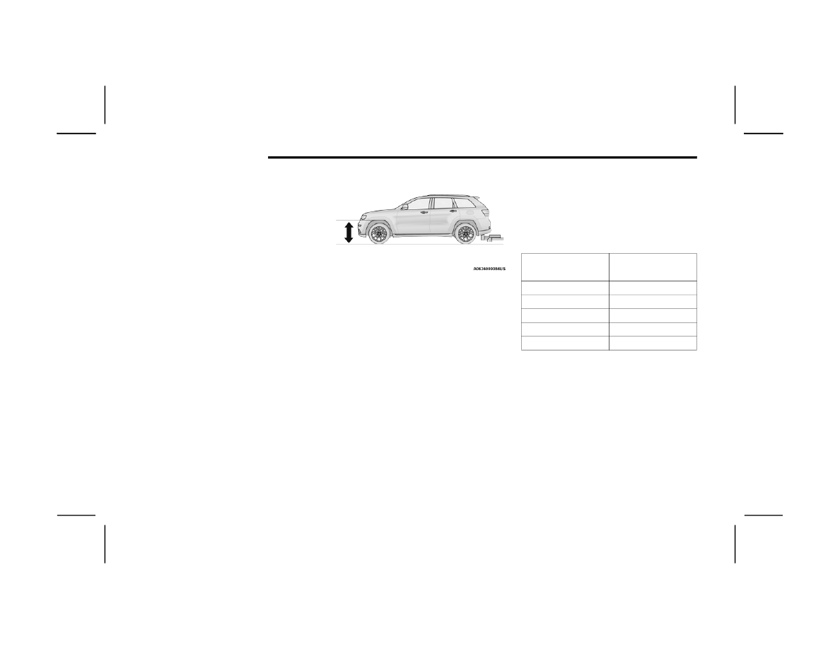
4. Measure the height from the top of the front 

wheel opening on the fender to the ground; 

this is height H1.

Measuring Height (H)

5. Attach the trailer to the vehicle without the 

weight distribution bars connected.

6. Measure the height from the top of the front 

wheel opening on the fender to the ground; 

this is height H2.

7. Install and adjust the tension in the weight 

distributing bars per the manufacturers’ 

recommendations so that the height of the 

front fender is approximately (H2-H1)/2+H1 

(about 1/2 the difference between H2 and H1 

above normal ride height [H1]).

8. Use the touchscreen radio settings and switch 

off tire jack mode. Make sure the truck returns 

to normal ride height. Perform a visual 

inspection of the trailer and weight distributing 

hitch to confirm the manufacturers’ 

recommendations have been met.

9. The vehicle can now be driven.

NOTE:

For all towing conditions, we recommend towing 

with TOW mode engaged (if equipped).

Measurement 

Example

Example Height (mm)

H1

925

H2

946

H2-H1

21

(H2-H1)/2

10.5

(H2-H1)/2 + H1

935.5

STARTING AND OPERATING

139

T

RAILER

 H

ITCH

 C

LASSIFICATION

The following chart provides the industry standard for the maximum trailer weight a given trailer hitch class can tow and should be used to assist you in selecting 

the correct trailer hitch for your intended towing condition.

Trailer Hitch Classification Definitions

Class

Max. Trailer Hitch Industry Standards

Class I - Light Duty

2,000 lb (907 kg)

Class II - Medium Duty

3,500 lb (1,587 kg)

Class III - Heavy Duty

6,000 lb (2,722 kg)

Class IV - Extra Heavy Duty

10,000 lb (4,535 kg)

For the Maximum Gross Trailer Weight (GTW) towable for your given drivetrain see  

Ú

page 140.

All trailer hitches should be professionally installed on your vehicle.

4

140

STARTING AND OPERATING


T

RAILER

 T

OWING

 W

EIGHTS

 (M

AXIMUM

 T

RAILER

 W

EIGHT

 R

ATINGS

)  

The following chart provides the maximum trailer weight ratings towable for your given drivetrain:

NOTE:

The trailer tongue weight must be considered as part of the combined weight of occupants and cargo, and should never exceed the weight referenced on the 

Tire and Loading Information placard  

Ú

page 291. The addition of passengers and cargo may require reducing trailer tongue load and GTW.

Engine

Frontal Area

Maximum GTW

Maximum Trailer TW 

(See Note)

3.6L - 4x2 (Std Cooling)

55 sq ft (5.11 sq m)

3,500 lb (1,587 kg)

350 lb (158 kg)

3.6L - 4x4 (Std Cooling)

55 sq ft (5.11 sq m)

3,500 lb (1,587 kg)

350 lb (158 kg)

3.6L - 4x2 (HD Cooling)

55 sq ft (5.11 sq m)

6,200 lb (2,812 kg)

620 lb (281 kg)

3.6L - 4x4 (HD Cooling)

55 sq ft (5.11 sq m)

6,200 lb (2,812 kg)

620 lb (281 kg)

Refer to local laws for maximum trailer towing speeds.

STARTING AND OPERATING

141

T

RAILER

 H

ITCH

 R

ECEIVER

 C

OVER


R

EMOVAL

 — I

F

 E

QUIPPED

Your vehicle may be equipped with a trailer hitch 

receiver cover, this must be removed to access the 

trailer hitch receiver (if equipped). This hitch 

receiver cover is located at the bottom center of 

the rear fascia.
1. Turn the two locking retainers located at the 

bottom of the hitch receiver cover a quarter 

turn counterclockwise.

NOTE:

Use a suitable tool such as a coin in the slot of the 

locking retainer if needed for added leverage.

Hitch Receiver Cover

2. Pull the bottom of the cover outward (towards 

you), pull downwards to disengage the tabs 

located at the top of the hitch receiver cover.

Hitch Receiver Cover

To reinstall the hitch receiver cover after towing 

repeat the procedure in reverse order.

NOTE:

Be sure to engage all tabs of the hitch receiver 

cover in the bumper fascia prior to installation.

T

RAILER

 A

ND

 T

ONGUE

 W

EIGHT


Never exceed the maximum tongue weight 

stamped on your bumper or trailer hitch.

Weight Distribution

1 — Hitch Receiver Cover
2 — Locking Retainers

CAUTION!

Always load a trailer with 60% of the weight in 

the front of the trailer. This places 10% of the 

GTW on the tow hitch of your vehicle. Loads 

balanced over the wheels or heavier in the rear 

can cause the trailer to sway severely side to 

side which will cause loss of control of the 

vehicle and trailer. Failure to load trailers heavier 

in front is the cause of many trailer collisions.

4

142

STARTING AND OPERATING


(Continued)

(Continued)

Consider the following items when computing the 

weight on the rear axle of the vehicle:

The tongue weight of the trailer.

The weight of any other type of cargo or equip

-

ment put in or on your vehicle.

The weight of the driver and all passengers.

NOTE:

Remember that everything put into or on the trailer 

adds to the load on your vehicle. Also, additional 

factory-installed options or dealer-installed options 

must be considered as part of the total load on 

your vehicle. Refer to the Tire And Loading Infor

-

mation placard for the maximum combined weight 

of occupants and cargo for your vehicle  

Ú

page 296.

T

OWING

 R

EQUIREMENTS


To promote proper break-in of your new vehicle 

drivetrain components, the following guidelines 

are recommended.

Perform the maintenance listed in Scheduled 

Servicing  

Ú

page 257. When towing a trailer, 

never exceed the Gross Axle Weight Rating or 

Gross Combined Weight Rating.

CAUTION!

Do not tow a trailer at all during the first 

500 miles (805 km) the new vehicle is driven. 

The engine, axle or other parts could be 

damaged.

Then, during the first 500 miles (805 km) that 

a trailer is towed, do not drive over 50 mph 

(80 km/h) and do not make starts at full 

throttle. This helps the engine and other parts 

of the vehicle wear in at the heavier loads.

WARNING!

Make certain that the load is secured in the 

trailer and will not shift during travel. When 

trailering cargo that is not fully secured, 

dynamic load shifts can occur that may be 

difficult for the driver to control. You could lose 

control of your vehicle and have a collision.

When hauling cargo or towing a trailer, do not 

overload your vehicle or trailer. Overloading 

can cause a loss of control, poor performance 

or damage to brakes, axle, engine, transmis

-

sion, steering, suspension, chassis structure 

or tires.

CAUTION!

Safety chains must always be used between 

your vehicle and trailer. Always connect the 

chains to the hook retainers of the vehicle 

hitch. Cross the chains under the trailer 

tongue and allow enough slack for turning 

corners.

Vehicles with trailers should not be parked on 

a grade. When parking, apply the parking 

brake on the tow vehicle. Put the tow vehicle 

transmission in PARK. For four-wheel drive 

vehicles, make sure the transfer case is not in 

NEUTRAL. Always, block or "chock" the trailer 

wheels.

GCWR must not be exceeded.

Total weight must be distributed between the 

tow vehicle and the trailer such that the 

following four ratings are not exceeded:

GVWR

GTW

GAWR

Tongue weight rating for the trailer hitch 

utilized.

WARNING!

STARTING AND OPERATING

143

Towing Requirements — Tires

Do not attempt to tow a trailer while using a 

compact spare tire.

Do not drive more than 50 mph (80 km/h) when 

towing while using a full size spare tire.

Proper tire inflation pressures are essential to 

the safe and satisfactory operation of your 

vehicle.

Check the trailer tires for proper tire inflation 

pressures before trailer usage.

Check for signs of tire wear or visible tire 

damage before towing a trailer.

Replacing tires with a higher load carrying 

capacity will not increase the vehicle's GVWR 

and GAWR limits.

For further information  

Ú

page 291.

Towing Requirements — Trailer Brakes

Do not interconnect the hydraulic brake system 

or vacuum system of your vehicle with that of 

the trailer. This could cause inadequate braking 

and possible personal injury.

An electronically actuated trailer brake 

controller is required when towing a trailer with 

electronically actuated brakes. When towing a 

trailer equipped with a hydraulic surge actuated 

brake system, an electronic brake controller is 

not required.

Trailer brakes are recommended for trailers 

over 1,000 lb (453 kg) and required for trailers 

in excess of 2,000 lb (907 kg).

WARNING!

Do not connect trailer brakes to your vehicle's 

hydraulic brake lines. It can overload your 

brake system and cause it to fail. You might 

not have brakes when you need them and 

could have an accident.

Towing any trailer will increase your stopping 

distance. When towing, you should allow for 

additional space between your vehicle and the 

vehicle in front of you. Failure to do so could 

result in an accident.

CAUTION!

If the trailer weighs more than 1,000 lb (453 kg) 

loaded, it should have its own brakes and they 

should be of adequate capacity. Failure to do 

this could lead to accelerated brake lining wear, 

higher brake pedal effort, and longer stopping 

distances.

4

144

STARTING AND OPERATING


Towing Requirements — Trailer Lights And 

Wiring

Whenever you pull a trailer, regardless of the trailer 

size, stop lights and turn signals on the trailer are 

required for motoring safety.
The Trailer Tow Package may include a four- and 

seven-pin wiring harness. Use a factory approved 

trailer harness and connector.

NOTE:

Do not cut or splice wiring into the vehicle’s wiring 

harness.
The electrical connections are all complete to the 

vehicle but you must mate the harness to a trailer 

connector. Refer to the following illustrations.

NOTE:

Disconnect trailer wiring connector from the 

vehicle before launching a boat (or any other 

device plugged into vehicle’s electrical connect) 

into water.

Be sure to reconnect once clear from water 

area.

Four-Pin Connector

Seven-Pin Connector

1 — Ground
2 — Park
3 — Left Stop/Turn
4 — Right Stop/Turn

1 — Backup Lamps
2 — Running Lamps
3 — Left Stop/Turn
4 — Ground
5 — Battery
6 — Right Stop/Turn
7 — Electric Brakes

STARTING AND OPERATING

145

T

OWING

 T

IPS


Before towing, practice turning, stopping, and 

backing up the trailer in an area located away from 

heavy traffic.

Automatic Transmission

Select the DRIVE (D) range when towing. The 

transmission controls include a drive strategy to 

avoid frequent shifting when towing. However, if 

frequent shifting does occur while in DRIVE, select 

TOW mode (if equipped), or use the AutoStick shift 

control to manually select a lower gear.

NOTE:

Using TOW mode (if equipped), or selecting a lower 

gear (using the AutoStick shift control) while oper

-

ating the vehicle under heavy loading conditions, 

will improve performance and extend transmission 

life by reducing excessive shifting and heat 

buildup. This action will also provide better 

engine braking.

AutoStick

When using the AutoStick shift control, select 

the highest gear that allows for adequate perfor

-

mance and avoids frequent downshifts. For 

example, choose “5” if the desired speed can be 

maintained. Choose “4” or “3” if needed to 

maintain the desired speed.

To prevent excess heat generation, avoid 

continuous driving at high RPM. Reduce vehicle 

speed as necessary to avoid extended driving at 

high RPM. Return to a higher gear or vehicle 

speed when grade and road conditions allow.

Cruise Control — If Equipped

Do not use on hilly terrain or with heavy loads.

When using the Cruise Control, if you experience 

speed drops greater than 10 mph (16 km/h), 

disengage until you can get back to cruising 

speed.

Use Cruise Control in flat terrain and with light 

loads to maximize fuel efficiency.

4

146

STARTING AND OPERATING


RECREATIONAL TOWING (BEHIND MOTORHOME) 

T

OWING

 T

HIS

 V

EHICLE

 B

EHIND

 A

NOTHER

 V

EHICLE

NOTE:

When towing your vehicle, always follow applicable state and provincial laws. Contact state and provincial Highway Safety offices for additional details.

A flat tow electric power steering enable kit is available for increased flat tow performance, contact an authorized dealer for further details.

Vehicles equipped with Quadra-Lift must be placed in Transport Mode before tying them down (from the body) on a trailer or flatbed truck  

Ú

page 103. 

If the vehicle cannot be placed in Transport mode (for example, engine will not run), tie-downs should be fastened over the tires using specific straps

(not to the body). Failure to follow these instructions may cause fault codes to be set and/or cause loss of proper tie-down tension.

Towing Condition

Wheels OFF The Ground

Two-Wheel Drive Models

Four-Wheel Drive Models 

Without 4WD Low

Four-Wheel Drive Models 

With 4WD Low

Flat Tow

NONE

NOT ALLOWED

NOT ALLOWED

See Instructions

Transmission in PARK

Transfer case in

N (NEUTRAL)

Tow in forward direction

Dolly Tow

Front

NOT ALLOWED

NOT ALLOWED

NOT ALLOWED

Rear

OK

NOT ALLOWED

NOT ALLOWED

On Trailer

ALL

OK

OK

OK

STARTING AND OPERATING

147

(Continued)

R

ECREATIONAL

 T

OWING

 — T

WO

 W

HEEL


D

RIVE

 M

ODELS

DO NOT flat tow this vehicle. Damage to the 

drivetrain will result.
Recreational towing (for two-wheel drive models) is 

allowed ONLY if the rear wheels are OFF the 

ground. This may be accomplished using a tow 

dolly or vehicle trailer. If using a tow dolly, follow 

this procedure:
1. Properly secure the dolly to the tow vehicle, 

following the dolly manufacturer's 

instructions.

NOTE:

If vehicle is equipped with Quadra-Lift air 

suspension, ensure the vehicle is set to Normal 

Ride Height.
2. Drive the rear wheels onto the tow dolly.
3. Firmly apply the parking brake. Shift the 

transmission into PARK.

4. Turn the ignition OFF.
5. Properly secure the rear wheels to the dolly, 

following the dolly manufacturer’s 

instructions.

6. Install a suitable clamping device, designed for 

towing, to secure the front wheels in the 

straight position.

R

ECREATIONAL

 T

OWING

 — 

Q

UADRA

-T

RAC

 I (S

INGLE

-S

PEED


T

RANSFER

 C

ASE

) F

OUR

-W

HEEL

 D

RIVE


M

ODELS

Recreational towing is not allowed. These models 

do not have a N (NEUTRAL) position in the transfer 

case.

NOTE:

This vehicle may be towed on a flatbed or vehicle 

trailer provided all four wheels are OFF the ground.

R

ECREATIONAL

 T

OWING

 — 

Q

UADRA

–T

RAC

 II/Q

UADRA

–D

RIVE

 II 

F

OUR

-W

HEEL

 D

RIVE

 M

ODELS

The transfer case must be shifted into N 

(NEUTRAL) and the transmission must be in PARK 

(P) for recreational towing. The N (NEUTRAL) 

selection button is adjacent to the transfer case 

selector switch. Shifts into and out of transfer case 

N (NEUTRAL) can take place with the selector 

switch in any mode position.

CAUTION!

Towing with the rear wheels on the ground will 

cause severe transmission damage. Damage 

from improper towing is not covered under the 

New Vehicle Limited Warranty.

CAUTION!

Towing this vehicle in violation of the above 

requirements can cause severe transmission 

and/or transfer case damage. Damage from 

improper towing is not covered under the New 

Vehicle Limited Warranty.

CAUTION!

DO NOT dolly tow any 4WD vehicle. Towing 

with only one set of wheels on the ground 

(front or rear) will cause severe transmission 

and/or transfer case damage. Tow with all 

four wheels either ON the ground, or OFF the 

ground (using a vehicle trailer).

Tow only in a forward direction. Towing this 

vehicle backwards can cause severe damage 

to the transfer case.

The transmission must be in PARK for recre

-

ational towing.

4

148

STARTING AND OPERATING


Shifting Into N (NEUTRAL)

Use the following procedure to prepare your 

vehicle for recreational towing:
1. Bring the vehicle to a complete stop on level 

ground, with the engine running.

2. Press and hold the brake pedal.
3. Shift the transmission into NEUTRAL.
4. If vehicle is equipped with Quadra-Lift air 

suspension, ensure the vehicle is set to 

Normal Ride Height.

NOTE:

Steps 1 through 4 are requirements that 

must be met before pushing the NEUTRAL 

(N) button, and must continue to be met 

until the shift has been completed. If any of 

these requirements are not met before 

pushing the N (NEUTRAL) button or are no 

longer met during the shift, then the N 

(NEUTRAL) indicator light will flash continu

-

ously until all requirements are met or until 

the N (NEUTRAL) button is released.

The ignition must be in the ON/RUN position 

for a shift to take place and for the position 

indicator lights to be operable. If the ignition 

is not in the ON/RUN position, the shift will 

not take place and no position indicator 

lights will be on or flashing.

A flashing N (NEUTRAL) position indicator 

light indicates that shift requirements have 

not been met.

If the vehicle is equipped with Quadra-Lift 

air suspension, the engine should be 

started and left running for a minimum of 

60 seconds (with all the doors closed) at 

least once every 24 hours. This process 

allows the air suspension to adjust the 

vehicle’s ride height to compensate for 

temperature effects.

5. Using a ballpoint pen or similar object, push 

and hold the recessed transfer case N 

(NEUTRAL) button (located by the selector 

switch) for four seconds. The light behind the 

N symbol will blink, indicating shift in progress. 

The light will stop blinking (stay on solid) when 

the shift to N (NEUTRAL) is complete. A “FOUR 

WHEEL DRIVE SYSTEM IN NEUTRAL” message 

will appear in the instrument cluster.

Before recreational towing, perform the proce

-

dure outlined under “Shifting into N 

(NEUTRAL)” to be certain that the transfer 

case is fully in N (NEUTRAL). Otherwise, 

internal damage will result.

Towing this vehicle in violation of the above 

requirements can cause severe transmission 

and/or transfer case damage. Damage from 

improper towing is not covered under the

New Vehicle Limited Warranty.

Do not use a bumper-mounted clamp-on tow 

bar on your vehicle. The bumper face bar will 

be damaged.

WARNING!

You or others could be injured or killed if you 

leave the vehicle unattended with the transfer 

case in the N (NEUTRAL) position without first 

fully engaging the parking brake. The transfer 

case N (NEUTRAL) position disengages both the 

front and rear driveshafts from the powertrain 

and will allow the vehicle to roll, even if the 

transmission is in PARK. The parking brake 

should always be applied when the driver is not 

in the vehicle.

CAUTION!

CAUTION!

It is necessary to follow these steps to be certain 

that the transfer case is fully in N (NEUTRAL) 

before recreational towing to prevent damage to 

internal parts.

STARTING AND OPERATING

149

N (NEUTRAL) Button

6. After the shift is completed and the N 

(NEUTRAL) light stays on, release the N 

(NEUTRAL) button.

7. Shift the transmission into REVERSE or DRIVE.
8. Release the brake pedal for five seconds and 

ensure that there is no vehicle movement.

9. Press and hold the brake pedal. Shift the 

transmission back into NEUTRAL.

10. Firmly apply the parking brake.
11. With the transmission and transfer case in 

NEUTRAL, push and hold the ENGINE START/

STOP button until the engine turns off.

12. Place the transmission gear selector in PARK. 

Release the brake pedal.

13. Push the ENGINE START/STOP button twice 

(without pressing the brake pedal), to turn the 

ignition to the off position.

14. Attach the vehicle to the tow vehicle using a 

suitable tow bar.

15. Release the parking brake.

Shifting Out Of N (NEUTRAL)

Use the following procedure to prepare your 

vehicle for normal usage:
1. Bring the vehicle to a complete stop, leaving 

it connected to the tow vehicle.

2. Firmly apply the parking brake.
3. Start the engine.

NOTE:

Steps 1 through 5 are requirements that 

must be met before pushing the N 

(NEUTRAL) button, and must continue to be 

met until the shift has been completed. If 

any of these requirements are not met 

before pushing the N (NEUTRAL) button or 

are no longer met during the shift, the N 

(NEUTRAL) indicator light will flash continu

-

ously until all requirements are met or until 

the N (NEUTRAL) button is released.

The ignition must be in the ON/RUN position 

for a shift to take place and for the position 

indicator lights to be operable. If the ignition 

is not in the ON/RUN position, the shift will 

not take place and no position indicator 

lights will be on or flashing.

A flashing N (NEUTRAL) position indicator 

light indicates that shift requirements have 

not been met.

4. Press and hold the brake pedal.
5. Shift the transmission into NEUTRAL.
6. Using a ballpoint pen or similar object, push 

and hold the recessed transfer case N 

(NEUTRAL) button (located by the selector 

switch) for one second.

N (NEUTRAL) Button

7. When the N (NEUTRAL) indicator light turns off, 

release the N (NEUTRAL) button. After the N 

(NEUTRAL) button has been released, the 

transfer case will shift to the position indicated 

by the selector switch.

8. Shift the transmission into PARK. Turn the 

engine off.

9. Release the brake pedal.

4

150

STARTING AND OPERATING


10. Disconnect vehicle from the tow vehicle.
11. Start the engine.
12. Press and hold the brake pedal.
13. Release the parking brake.
14. Shift the transmission into REVERSE or DRIVE, 

release the brake pedal, and check that the 

vehicle operates normally.

DRIVING TIPS

O

N

-R

OAD

 D

RIVING

 T

IPS

Utility vehicles have higher ground clearance and a 

narrower track to make them capable of 

performing in a wide variety of off-road 

applications. Specific design characteristics give 

them a higher center of gravity than conventional 

passenger cars.
An advantage of the higher ground clearance is a 

better view of the road, allowing you to anticipate 

problems. They are not designed for cornering at 

the same speeds as conventional passenger cars 

any more than low-slung sports cars are designed 

to perform satisfactorily in off-road conditions. 

Avoid sharp turns or abrupt maneuvers. As with 

other vehicles of this type, failure to operate this 

vehicle correctly may result in loss of control or 

vehicle rollover.

O

FF

-R

OAD

 D

RIVING

 T

IPS

NOTE:

Prior to off-road driving with non-Summit models 

that are also equipped with an Off-Road Package, 

remove the lower fascia to prevent damage. The 

lower fascia is attached to the lower part of the 

front fascia with seven quarter turn fasteners and 

can be removed by hand. The front license plate 

bracket must be removed first (if equipped).

Front Air Dam

NOTE:

On Summit models the lower front fascia is not 

removable.

Lower Front Fascia Removal:
1. Remove the seven quarter turn fasteners.
2. Starting on one side of the vehicle, disengage 

lower fascia from the upper fascia. Grab the 

portion inside the wheel well. Pulling it 

downwards and toward you, separate the tabs 

from the slots in the upper fascia.

3. Continue working your way across the vehicle, 

separating the remaining tabs from the slots in 

the upper fascia.

NOTE:

Do not allow the lower fascia to freely hang from 

the tabs in the opposite corner as damage to lower 

and upper fascia may result.
4. Store the lower fascia in a safe location.

NOTE:

It is recommend to also remove the radar sensor 

on vehicles equipped with Adaptive Cruise Control 

(ACC). This radar sensor is specifically calibrated to 

your vehicle and is not interchangeable with other 

radar sensors.
Radar Sensor Removal Procedure (If Equipped 

With Adaptive Cruise Control [ACC]):
1. With the lower fascia removed, which 

provides access to the sensor and bracket, 

disconnect the wiring harness from the 

sensor.

1 — Front Bumper
2 — Front Air Dam Fasteners

STARTING AND OPERATING

151

2. Using a suitable tool, disconnect the wire clip 

from the bracket.

NOTE:

Before the next step, it is recommended to scribe 

location to assist in reinstallation.
3. Using a suitable tool, remove the two fasteners 

that hold the sensor bracket to the bumper 

beam.

4. Locate the protective connector on the rear of 

the bumper beam.

Bumper Beam

NOTE:

Only models with the Off-Road Package are 

equipped with a protective connector.
5. Remove the plug from the protective 

connector and install on the sensor.

6. Insert the wiring harness connector into the 

protective connector.

7. Store sensor and bracket in a safe place.

NOTE:

All Speed Control functions will be disabled when 

the radar sensor is disconnected.

Radar Sensor Installation Procedure (If Equipped 

With Adaptive Cruise Control [ACC]):
1. Disconnect the wiring harness connector 

from the protective connector on the bumper 

beam.

2. Remove plug from radar sensor and install in 

protective connector.

3. Using the previously scribed marks, reinstall 

the radar sensor and bracket using the two 

fasteners.

NOTE:

Some alignment may be required upon fascia 

installation to align sensor with fascia.

4. Install the wiring harness connector into the 

radar sensor.

NOTE:

If you receive a fault, see an authorized dealer. 

They may need to perform a sensor alignment.

Lower Front Fascia Installation

NOTE:

This will only work if you have a helper.
1. Starting at the center of the vehicle, engage a 

sufficient number of tabs to support the 

weight of the lower fascia (typically one or

two tabs) into the upper fascia.

2. Working your way outward, engage the tabs 

into the slots on one side of the vehicle.

3. Return to the center of the vehicle and repeat 

Step 2 to the opposite side of the vehicle.

NOTE:

It may be necessary to apply additional 

force to individual tabs to make sure they 

are fully engaged.

Do not use any tools to apply additional 

force to the tabs as damage to the upper 

and lower fascias may result.

4. Reinstall the seven quarter turn fasteners.

1 — Inside Bumper Beam
2 — Protective Connector Location
3 — Sensor Bracket Fasteners
4 — Sensor Bracket

4

152

STARTING AND OPERATING


Quadra-Lift — If Equipped

When off-roading, it is recommended that the 

lowest useable vehicle height that will clear the 

current obstacle or terrain be selected. The vehicle 

height should then be raised as required by the 

changes in terrain.
The Selec-Terrain system will automatically change 

the vehicle to the optimized height based on the 

Selec-Terrain switch position. The vehicle height 

can be changed from the default height for each 

Selec-Terrain mode by normal use of the air 

suspension switches  

Ú

page 101.

When To Use 4WD LOW Range —

If Equipped

When off-road driving, shift to 4WD LOW for 

additional traction. This range should be limited to 

extreme situations such as deep snow, mud, or 

sand where additional low speed pulling power is 

needed. Vehicle speeds in excess of 25 mph 

(40 km/h) should be avoided when in 4WD LOW 

range.

Driving Through Water

Although your vehicle is capable of driving through 

water, there are a number of precautions that 

must be considered before entering the water.

NOTE:

Your vehicle is capable of water fording in up to 

20 inches (51 cm) of water, while crossing small 

rivers or streams. To maintain optimal perfor

-

mance of your vehicle's heating and ventilation 

system it is recommended to switch the system 

into recirculation mode during water fording.

Driving through water more than a few inches/

centimeters deep will require extra caution to 

ensure safety and prevent damage to your vehicle. 

If you must drive through water, try to determine 

the depth and the bottom condition (and location 

of any obstacles) prior to entering. Proceed with 

caution and maintain a steady controlled speed 

less than 5 mph (8 km/h) in deep water to 

minimize wave effects.
Flowing Water
If the water is swift flowing and rising (as in storm 

run-off), avoid crossing until the water level 

recedes and/or the flow rate is reduced. If you 

must cross flowing water avoid depths in excess of 

9 inches (23 cm). The flowing water can erode the 

streambed, causing your vehicle to sink into 

deeper water. Determine exit point(s) that are 

downstream of your entry point to allow for drifting.
Standing Water
Avoid driving in standing water deeper than 

20 inches (51 cm), and reduce speed 

appropriately to minimize wave effects. Maximum 

speed is 5 mph (8 km/h).

WARNING!

Do not drive in 4WD LOW on dry pavement; 

driveline damage may result. 4WD-LOW locks 

front and rear drivelines together and does not 

allow for differential action between the front to 

rear driveshafts. Driving in 4WD LOW on 

pavement will cause driveline binding; use only 

on wet or slippery surfaces.

CAUTION!

When driving through water, do not exceed 

5 mph (8 km/h). Always check water depth 

before entering as a precaution, and check all 

fluids afterward. Driving through water may 

cause damage that may not be covered by the 

New Vehicle Limited Warranty.

STARTING AND OPERATING

153

Maintenance
After driving through deep water, inspect your 

vehicle fluids and lubricants (engine oil, 

transmission oil, axle, transfer case) to ensure the 

fluids have not been contaminated. Contaminated 

fluid (milky, foamy in appearance) should be 

flushed/changed as soon as possible to prevent 

component damage.

Driving In Snow, Mud And Sand

In heavy snow, when pulling a load, or for 

additional control at slower speeds, shift the 

transmission to a low gear and shift the transfer 

case to 4WD LOW if necessary  

Ú

page 101. Only 

shift into a lower gear to maintain forward motion. 

Over-revving the engine can spin the wheels and 

traction will be lost.
Avoid abrupt downshifts on icy or slippery roads, 

because engine braking may cause skidding and 

loss of control.

Hill Climbing

NOTE:

Before attempting to climb a hill, determine the 

conditions at the crest and/or on the other side.
Before climbing a steep hill, shift the transmission 

to a lower gear and shift the transfer case to 

4WD LOW. Use first gear and 4WD LOW for very 

steep hills.
If you stall or begin to lose forward motion while 

climbing a steep hill, allow your vehicle to come to 

a stop and immediately apply the brakes. Restart 

the engine, and shift into REVERSE (R). Back slowly 

down the hill, allowing the compression braking of 

the engine to help regulate your speed. If the 

brakes are required to control vehicle speed, apply 

them lightly and avoid locking or skidding the tires.

Remember, never drive diagonally across a hill. 

Always drive straight up or down.
If the wheels start to slip as you approach the crest 

of a hill, ease off the accelerator and maintain 

forward motion by turning the front wheels slowly. 

This may provide a fresh “bite” into the surface and 

will usually provide traction to complete the climb.

Traction Downhill

When descending mountains or hills, use Hill 

Descent Control or Selec-Speed Control to avoid 

repeated heavy braking.
If not equipped with Hill Descent Control or 

Selec-Speed Control use the following procedure:
Shift the transmission into a low gear, and the 

transfer case into 4WD LOW range. Let the vehicle 

go slowly down the hill with all four wheels turning 

against engine compression drag. This will permit 

you to control the vehicle speed and direction.
When descending mountains or hills, repeated 

braking can cause brake fade with loss of braking 

control. Avoid repeated heavy braking by 

downshifting the transmission whenever possible.

WARNING!

If the engine stalls, you lose forward motion, or 

cannot make it to the top of a steep hill or grade, 

never attempt to turn around. To do so may 

result in tipping and rolling the vehicle. Always 

back carefully straight down a hill in REVERSE 

gear. Never back down a hill in NEUTRAL using 

only the brake.

4


Content      ..     7      8      9      10     ..