Jeep Grand Cherokee WK (2022 year). Manual in english - page 4
 

  Index      Manuals     Jeep Grand Cherokee WK (2022 year). Manual in english


Search            copyright infringement  


Content      ..     2      3      4      5     ..


Jeep Grand Cherokee WK (2022 year). Manual in english - page 4


58

GETTING TO KNOW YOUR VEHICLE


Once the audio device is connected and 

synchronized to the vehicle’s USB control system 

(an external USB device may take a few minutes to 

connect), the audio device starts charging and is 

ready for use.

NOTE:

If the audio device battery is completely 

discharged, it may not communicate with the USB 

control system until a minimum charge is attained. 

Leaving the audio device connected to the USB 

control system can charge it to the required level.

Using This Feature

By using an external USB device to connect to the 

USB port: 

The audio device can be played on the vehicle’s 

sound system, providing metadata (artist, track 

title, album, etc.) information on the radio 

display.

NOTE:

Depending on track configuration, track infor

-

mation may not be present on the radio display.

The audio device can be controlled using the 

radio buttons to Play, Browse, and List the 

contents.

The audio device battery charges when plugged 

into the USB connector (if supported by the 

specific audio device).

NOTE:

For further information, refer to the Uconnect 

Owner’s Manual Supplement.

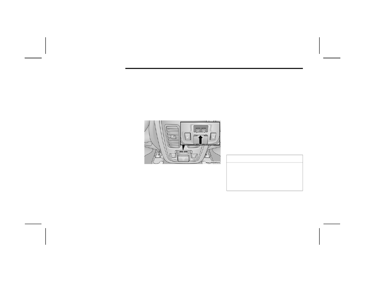
Second Row USB Charging Port

Second row USB connector ports can be used for 

charging purposes only. Use the connection cable 

to connect an external USB device to the charging 

ports which are located on the rear of the center 

console.

Rear Center Console USB Ports

NOTE:

Charge unsupported devices with the Charge Only 

USB ports. If an unsupported device is plugged into 

a Media USB port, a message will display on the 

touchscreen that the device is not supported by 

the system.

P

OWER

 O

UTLETS


Your vehicle is equipped with 12 Volt (15 Amp) 

power outlets that can be used to power cellular 

phones, small electronics and other low powered 

electrical accessories. The power outlets are 

labeled with either a “key” or a “battery” symbol to 

indicate how the outlet is powered. Power outlets 

labeled with a key symbol are powered when the 

ignition is in the ON or ACC position, while the 

outlets labeled with a battery symbol are 

connected directly to the battery and powered at 

all times.

NOTE:

All accessories connected to the battery powered 

outlets should be removed or turned off when the 

vehicle is not in use to protect the battery against 

discharge.

CAUTION!

Power outlets are designed for accessory plugs 

only. Do not insert any other object in the power 

outlets as this will damage the outlet and blow 

the fuse. Improper use of the power outlet can 

cause damage not covered by your New Vehicle 

Limited Warranty.

GETTING TO KNOW YOUR VEHICLE

59

The front power outlet is located inside the storage 

area on the center stack of the instrument panel. 

Push inward on the storage lid to open the 

compartment and gain access to this power outlet.

Front Power Outlet

In addition to the front power outlet, there is also a 

power outlet located in the storage area of the 

center console.

Center Console Outlet

The rear power outlet is located in the right rear 

cargo area.

Rear Cargo Power Outlet

NOTE:

The rear power outlet can be switched from 

ignition only to battery powered all the time. See 

your local authorized dealer for details.

Power Outlet Right Rear Quarter Panel Fuse

2

60

GETTING TO KNOW YOUR VEHICLE


(Continued)

Power Outlet Fuse Locations

P

OWER

 I

NVERTER

 — I

F

 E

QUIPPED

There is a 115 Volt, 150 Watt inverter outlet 

located on the back of the center console to 

convert DC current to AC current. This outlet can 

power cellular phones, electronics and other low 

power devices requiring power up to 150 Watts.

NOTE:

Certain video game consoles, new computers and 

power tools will exceed this power limit.

Power Inverter

The power inverter is designed with built-in 

overload protection. If the power rating of 150 

Watts is exceeded, the power inverter will 

automatically shut down. Once the electrical 

device has been removed from the outlet, the 

inverter should automatically reset. To avoid 

overloading the circuit, check the power ratings on 

electrical devices prior to using the inverter.

1 — F104 Fuse 20 Amp Yellow Power Outlet

Console Bin
2 — F90–F91 Fuse 20 Amp Yellow Power Outlet 

Right Rear Quarter Panel
3 — F93 Fuse 20 Amp Yellow Cigar Lighter

Instrument Panel

WARNING!

To avoid serious injury or death:

Only devices designed for use in this type of 

outlet should be inserted into any 12 Volt 

outlet.

Do not touch with wet hands.

Close the lid when not in use and while driving 

the vehicle.

If this outlet is mishandled, it may cause an 

electric shock and failure.

CAUTION!

Many accessories that can be plugged in draw 

power from the vehicle's battery, even when 

not in use (i.e., cellular phones, etc.). Eventu

-

ally, if plugged in long enough, the vehicle's 

battery will discharge sufficiently to degrade 

battery life and/or prevent the engine from 

starting.

Accessories that draw higher power (i.e., 

coolers, vacuum cleaners, lights, etc.) will 

degrade the battery even more quickly. Only 

use these intermittently and with greater 

caution.

After the use of high power draw accessories, 

or long periods of the vehicle not being started 

(with accessories still plugged in), the vehicle 

must be driven a sufficient length of time to 

allow the generator to recharge the vehicle's 

battery.

WARNING!

GETTING TO KNOW YOUR VEHICLE

61

WINDOWS

P

OWER

 W

INDOW

 C

ONTROLS

The window controls on the driver's door control all 

the door windows.

Power Window Switches

The passenger door windows can also be operated 

by using the single window controls on the 

passenger door trim panel. The window controls 

will operate only when the ignition is in the ACC or 

ON/RUN position.
To open the window part way (manually), push the 

window switch down briefly and release.
If equipped, the key fob may also be used to raise 

or lower vehicle windows while the ignition is in the 

OFF position.

NOTE:

The power window switches will remain active for 

up to 10 minutes after the ignition is placed in the 

OFF position. Opening either front door will cancel 

this feature. The time is programmable within 

Uconnect Settings  

Ú

page 155.

A

UTOMATIC

 W

INDOW

 F

EATURES


Auto-Down Feature
The driver and front passenger door power window 

switches have an Auto-Down feature. Push the 

window switch down for a short period of time, 

then release, and the window will go down 

automatically.
To stop the window from going all the way down 

during the Auto-Down operation, pull up or push 

down on the switch briefly.
Auto-Up Feature With Anti-Pinch Protection
Lift the window switch up for a short period of time 

and release; the window will go up automatically.
To stop the window from going all the way up 

during the Auto-Up operation, push down on the 

switch briefly.
To close the window part way, lift the window 

switch briefly and release it when you want the 

window to stop.
If the window runs into any obstacle during 

auto-closure, it will reverse direction and then go 

back down. Remove the obstacle and use the 

window switch again to close the window.

NOTE:

Any impact due to rough road conditions may 

trigger the auto-reverse function unexpectedly 

during auto-closure. If this happens, pull the switch 

lightly and hold to close the window manually.

WARNING!

To avoid serious injury or death:

Do not insert any objects into the receptacles.

Do not touch with wet hands.

Close the lid when not in use.

If this outlet is mishandled, it may cause an 

electric shock and failure.

WARNING!

Never leave children unattended in a vehicle, 

and do not let children play with power windows. 

Do not leave the key fob in or near the vehicle, or 

in a location accessible to children, and do not 

leave the Keyless Enter ‘n Go™ Ignition in the 

ACC or ON/RUN position. Occupants, particularly 

unattended children, can become entrapped by 

the windows while operating the power window 

switches. Such entrapment may result in serious 

injury or death.

2

62

GETTING TO KNOW YOUR VEHICLE


(Continued)

R

ESET

 A

UTO

-U

P

Should the Auto-Up feature stop working, the 

window probably needs to be reset. To reset 

Auto-Up:
1. Pull the window switch up to close the window 

completely and continue to hold the switch up 

for an additional two seconds after the 

window is closed.

2. Push the window switch down firmly to open 

the window completely and continue to hold 

the switch down for an additional two seconds 

after the window is fully open.

W

INDOW

 L

OCKOUT

 S

WITCH

The window lockout switch on the driver's door trim 

panel allows you to disable the window controls on 

the rear passenger doors. To disable the window 

controls, push and release the window lockout 

button. To enable the window controls, push and 

release the window lockout button again.

Window Lockout Switch

W

IND

 B

UFFETING


Wind buffeting can be described as the perception 

of pressure on the ears or a helicopter-type sound in 

the ears. Your vehicle may exhibit wind buffeting 

with the windows down, or the sunroof (if equipped) 

in certain open or partially open positions. This is a 

normal occurrence and can be minimized. If the 

buffeting occurs with the rear windows open, open 

the front and rear windows together to minimize the 

buffeting. If the buffeting occurs with the sunroof 

open, adjust the sunroof opening to minimize the 

buffeting or open any window.

POWER SUNROOF — IF EQUIPPED

The power sunroof switch is located between the 

sun visors on the overhead console.

Power Sunroof Switch

WARNING!

There is no anti-pinch protection when the 

window is almost closed. To avoid personal 

injury be sure to clear your arms, hands, fingers 

and all objects from the window path before 

closing.

WARNING!

Never leave children unattended in a vehicle, 

or with access to an unlocked vehicle. Never 

leave the key fob in or near the vehicle, or in a 

location accessible to children. Do not leave 

the Keyless Enter ‘n Go™ Ignition in the ACC or 

ON/RUN position. Occupants, particularly 

unattended children, can become entrapped 

by the power sunroof while operating the 

power sunroof switch. Such entrapment may 

result in serious injury or death.

GETTING TO KNOW YOUR VEHICLE

63

O

PENING

 A

ND

 C

LOSING

 T

HE

 S

UNROOF

Express Open/Close
Push the switch rearward and release it within 

one-half second and the sunroof will open 

automatically from any position. The sunroof will 

open fully and stop automatically.
Push the switch forward and release it within 

one-half second and the sunroof will close 

automatically from any position. The sunroof will 

close fully and stop automatically.
During Express Open or Express Close operation, 

any other movement of the sunroof switch will stop 

the sunroof.

Manual Open/Close
To open the sunroof, push and hold the switch 

rearward to full open.
To close the sunroof, push and hold the switch in 

the forward position.
Any release of the switch during open or close 

operation will stop the sunroof movement. The 

sunroof will remain in a partially opened position 

until the switch is operated and held again.
Venting The Sunroof
Push and release the Vent button within one-half 

second and the sunroof will open to the vent 

position. This is called Express Vent and it will 

occur regardless of sunroof position. During 

Express Vent operation, any movement of the 

switch will stop the sunroof.

P

INCH

 P

ROTECT

 F

EATURE

This feature will detect an obstruction in the 

closing of the sunroof during the Express Close 

operation. If an obstruction in the path of the 

sunroof is detected, the sunroof will automatically 

retract. Remove the obstruction if this occurs.

NOTE:

If three consecutive sunroof close attempts result 

in Pinch Protect reversals, Pinch Protect will 

disable and the sunroof must be closed in Manual 

Mode.

S

UNSHADE

 O

PERATION

The sunshade can be opened manually. However, 

the sunshade will open automatically as the 

sunroof opens.

NOTE:

The sunshade cannot be closed if the sunroof is 

open.

S

UNROOF

 M

AINTENANCE

Use only a non-abrasive cleaner and a soft cloth to 

clean the glass panel. Periodically check for and 

clear out any debris that may have collected in the 

tracks.

In a collision, there is a greater risk of being 

thrown from a vehicle with an open sunroof. 

You could also be seriously injured or killed. 

Always fasten your seat belt properly and 

make sure all passengers are also properly 

secured.

Do not allow small children to operate the 

sunroof. Never allow your fingers, other body 

parts, or any object, to project through the 

sunroof opening. Injury may result.

WARNING!

2

64

GETTING TO KNOW YOUR VEHICLE


COMMANDVIEW SUNROOF WITH POWER 

SHADE — IF EQUIPPED  

The CommandView sunroof switch is located to the 

left between the sun visors on the overhead 

console.
The power shade switch is located to the right 

between the sun visors on the overhead console.

CommandView Sunroof And Power Shade Switches

O

PENING

 A

ND

 C

LOSING

 T

HE

 S

UNROOF

The sunroof has two programmed automatic stops 

for the sunroof open position: a comfort stop 

position and a full open position. The comfort stop 

position has been optimized to minimize wind 

buffeting.

Express Open/Close
Push the switch rearward and release it within 

one-half second and the sunroof will open 

automatically from any position. The sunroof will 

open fully and stop automatically.
Push the switch forward and release it within 

one-half second and the sunroof will close 

automatically from any position. The sunroof will 

close fully and stop automatically.
During Express Open or Express Close operation, 

any other movement of the sunroof switch will stop 

the sunroof.
Manual Open/Close
To open the sunroof, push and hold the switch 

rearward to full open.
To close the sunroof, push and hold the switch in 

the forward position.
Any release of the switch during open or close 

operation will stop the sunroof movement. The 

sunroof will remain in a partially opened position 

until the switch is operated and held again.

NOTE:

If the sunshade is in the closed position when 

Express or Manual Open operation is initiated the 

sunshade will automatically open to the half open 

position prior to the sunroof opening.

1 — Sunroof Switch
2 — Power Shade Switch

WARNING!

Never leave children unattended in a vehicle, 

or with access to an unlocked vehicle. Never 

leave the key fob in or near the vehicle, or in a 

location accessible to children. Do not leave 

the Keyless Enter ‘n Go™ Ignition in the ACC or 

ON/RUN position. Occupants, particularly 

unattended children, can become entrapped 

by the power sunroof while operating the 

power sunroof switch. Such entrapment may 

result in serious injury or death.

In a collision, there is a greater risk of being 

thrown from a vehicle with an open sunroof. 

You could also be seriously injured or killed. 

Always fasten your seat belt properly and 

make sure all passengers are also properly 

secured.

Do not allow small children to operate the 

sunroof. Never allow your fingers, other body 

parts, or any object, to project through the 

sunroof opening. Injury may result.

GETTING TO KNOW YOUR VEHICLE

65

Venting The Sunroof
Push and release the Vent button within one-half 

second and the sunroof will open to the vent 

position. This is called Express Vent, and it will 

occur regardless of sunroof position. During 

Express Vent operation, any movement of the 

switch will stop the sunroof.

NOTE:

If the sunshade is in the closed position when the 

vent switch is pushed, the sunshade will automati

-

cally cycle to the halfway open position prior to the 

sunroof opening to the Vent position.

O

PENING

 A

ND

 C

LOSING

 T

HE

 P

OWER


S

UNSHADE

The sunshade has two programmed positions: half 

open and full open positions. When operating the 

sunshade from the closed position, the sunshade 

will always stop at the half open position 

regardless of express or manual open operation. 

The switch must be actuated again to continue on 

to full open position.
If the sunroof is open or vented, the sunshade 

cannot be closed beyond the half open position. 

Pushing the sunshade close switch when the 

sunroof is open/vented and the sunshade is at half 

open position will first automatically close the 

sunroof prior to the sunshade closing.

Express Open/Close
Push the sunshade switch rearward and release it 

within one-half second, the sunshade will open to 

the half open position and stop automatically. 

Push and release the switch again from the half 

open position and the sunshade will open to the 

full open position and stop automatically.
Push the sunshade switch forward and release it 

within one-half second and the sunshade will close 

automatically.
During Express Open or Express Close operation, 

any other actuation of the sunroof switches will 

stop the sunshade in a partially open position.
Manual Open/Close
Push and hold the sunshade switch rearward, the 

sunshade will open to the half open position and 

stop automatically. Push and hold the sunshade 

switch again and the sunshade will open to the full 

open position.
Push and hold the switch forward and the 

sunshade will close and stop at full closed position.
Releasing the switch while the sunshade is in 

motion will stop the sunshade in a partially open 

position.

P

INCH

 P

ROTECT

 F

EATURE

This feature will detect an obstruction in the 

opening of the sunroof during Express Close 

operation. If an obstruction in the path of the 

sunroof is detected, the sunroof will automatically 

retract. Remove the obstruction if this occurs.

NOTE:

If three consecutive sunroof close attempts result 

in Pinch Protect reversals, Pinch Protect will 

disable and the sunroof must be closed in Manual 

Mode.

S

UNROOF

 M

AINTENANCE

Use only a non-abrasive cleaner and a soft cloth to 

clean the glass panel. Periodically check for and 

clear out any debris that may have collected in the 

tracks.

2

66

GETTING TO KNOW YOUR VEHICLE


HOOD    

T

O

 O

PEN

 T

HE

 H

OOD

To open the hood, two latches must be released.
1. Pull the release lever located at the bottom of 

the driver’s side of the instrument panel.

Hood Release

2. Reach under the hood, move safety latch to 

the left and lift the hood.

Safety Latch Location

T

O

 C

LOSE

 T

HE

 H

OOD

In one continuous motion, pull down on the front 

edge ofthe hood with moderate force until the 

angle is below the pointwhere the gas props are no 

longer resisting. Then let the hood continue tofall 

into the closed position on its own.

LIFTGATE

T

O

 U

NLOCK

/O

PEN

 T

HE

 L

IFTGATE

The liftgate may be released in several ways:

Key fob

Outside handle

Button on overhead console

The liftgate passive entry unlock feature is built 

into the electronic liftgate release handle. With a 

valid Passive Entry key fob within 5 ft (1.5 m) of the 

liftgate, push the electronic liftgate release handle 

to open. Push the button on the key fob twice 

within five seconds to release the liftgate.

NOTE:

When you push the button on the liftgate, either 

only the liftgate will unlock or all doors and the 

liftgate will unlock, depending on the selected 

setting in the Uconnect system  

Ú

page 155.

WARNING!

Be sure the hood is fully latched before driving 

your vehicle. If the hood is not fully latched, it 

could open when the vehicle is in motion and 

block your vision. Failure to follow this warning 

could result in serious injury or death.

GETTING TO KNOW YOUR VEHICLE

67

Passive Entry/Lock Button Location

NOTE:

Use the power door lock switch on either front door 

trim panel or the key fob to lock and unlock the 

liftgate. The manual door locks on the doors and 

the driver's door lock cylinder will not lock and 

unlock the liftgate.

T

O

 L

OCK

/C

LOSE

 T

HE

 L

IFTGATE

To manually close the liftgate, grab the liftgate 

closing handle and pull in a downward motion to 

close the liftgate.
With a valid Passive Entry key fob within 5 ft 

(1.5 m) of the liftgate, pushing the Passive Entry 

lock button, located next to the electronic release 

handle, will lock the vehicle.
The power liftgate may be closed by pushing the 

button, located in the upper left trim in the liftgate 

opening. This button cannot be used to open the 

liftgate.

NOTE:

The liftgate unlock feature is built into the elec

-

tronic liftgate release handle.

P

OWER

 L

IFTGATE

 — I

F

 E

QUIPPED


The power liftgate may be opened by 

pushing the electronic liftgate release 

handle  

Ú

page 23, or by pushing the 

liftgate button on the key fob. Push the 

liftgate button on the key fob twice within five 

seconds to open or close the power liftgate.

NOTE:

When using the liftgate button on the key fob to 

open the liftgate while the vehicle is locked, only 

the liftgate will unlock leaving the other doors to 

remain locked. Closing the liftgate will not relock 

the liftgate. The lock button on the key fob, or 

the Passive Entry lock button must be pushed to 

relock.

If the electronic release handle is used to unlock 

and open the liftgate and all the doors unlock, 

the liftgate and vehicle doors must be locked 

again. Use the key fob, Passive Entry lock 

button, or the power door lock switches on the 

front door panels.

The power liftgate may also be opened or closed by 

pushing the liftgate button located on the front 

overhead console. If the liftgate is fully open, the 

liftgate can be closed by pushing the liftgate button 

located on the left rear trim panel. If the liftgate is 

in motion, pushing the button again will reverse the 

liftgate.
When the liftgate button on the key fob is pushed 

two times, the turn signals will flash to signal that 

the liftgate is opening or closing (if Flash Lamps 

with Lock is enabled in the Uconnect Settings), and 

the liftgate chime will be audible. The chime can be 

turned on or off through the Uconnect Settings  

Ú

page 155.

1 — Electronic Liftgate Release
2 — Passive Entry Lock Button Location

WARNING!

Driving with the liftgate open can allow 

poisonous exhaust gases into your vehicle. You 

and your passengers could be injured by these 

fumes. Keep the liftgate closed when you are 

operating the vehicle.

2

68

GETTING TO KNOW YOUR VEHICLE


NOTE:

In the event of a power malfunction to the lift

-

gate, an emergency liftgate latch release can be 

used to open the liftgate. The emergency liftgate 

latch release can be accessed through a snap-in 

cover located on the liftgate trim panel.

If the liftgate is left open for an extended period 

of time, the liftgate may need to be closed 

manually to reset power liftgate functionality.

NOTE:

The power liftgate will not operate in tempera

-

tures below −22°F (−30°C) or temperatures 

above 150°F (65°C). Be sure to remove any 

buildup of snow or ice from the liftgate before 

pushing any of the power liftgate switches.

If anything obstructs the power liftgate while it is 

closing or opening, the liftgate will automatically 

reverse to the closed or open position. After 

multiple obstructions in the same cycle, the lift

-

gate will automatically stop and must be opened 

or closed manually.

There are pinch sensors attached to the side of 

the liftgate. Light pressure anywhere along 

these strips will cause the liftgate to return to 

the open position.

If the liftgate is only partially open, push the lift

-

gate button on the key fob twice to operate the 

liftgate.

If the electronic liftgate release handle is 

pushed while the power liftgate is opening, the 

liftgate motor will disengage to allow manual 

operation.

C

ARGO

 A

REA

 F

EATURES


Cargo Storage Bins — If Equipped 

There are up to four removable storage bins 

located in the rear cargo area. There are two 

storage bins located on either side of the cargo 

area.

NOTE:

If your vehicle is equipped with a rear subwoofer, 

the storage bin on that side will not be available.

Rear Storage Bin

WARNING!

During power operation, personal injury or cargo 

damage may occur. Ensure the liftgate travel 

path is clear. Make sure the liftgate is closed 

and latched before driving away.

WARNING!

Driving with the liftgate open can allow 

poisonous exhaust gases into your vehicle. 

You and your passengers could be injured by 

these fumes. Keep the liftgate closed when 

you are operating the vehicle.

If you are required to drive with the liftgate 

open, make sure that all windows are closed, 

and the climate control blower switch is set at 

high speed. Do not use the recirculation 

mode.

GETTING TO KNOW YOUR VEHICLE

69

Two additional storage bins may be located under 

the load floor. To access the lower storage bins, 

raise the load floor and if equipped, attach the 

tether strap (attached to the bottom of the load 

floor) to the liftgate opening.

Tether Strap

Rear Lower Storage Bins (If Equipped)

Retractable Cargo Area Cover —

If Equipped 

The purpose of this cover is for privacy, not to 

secure loads. It will not prevent cargo from shifting 

or protect passengers from loose cargo.
To cover the cargo area:
1. Grab the cover at the center handle and pull 

over the cargo area.

2. Insert the pins on the ends of the cover into the 

slots in the pillar trim cover.

3. The liftgate may be opened with the cargo 

cover in place.

Rear Cargo Cover

WARNING!

In a collision, a loose cargo cover in the vehicle 

could cause injury. It could fly around in a 

sudden stop and strike someone in the vehicle. 

Do not store the cargo cover on the cargo floor 

or in the passenger compartment. Remove the 

cover from the vehicle when taken from its 

mounting. Do not store it in the vehicle.

2

70

GETTING TO KNOW YOUR VEHICLE


(Continued)

(Continued)

Rear Cargo Tie-Downs 

The rear cargo tie-downs, located on the cargo 

area floor, should be used to safely secure loads 

when the vehicle is moving.

Rear Cargo Tie-Downs

ROOF LUGGAGE RACK — IF EQUIPPED 

The crossbars and siderails are designed to carry 

loads on vehicles equipped with a luggage rack. 

The load must not exceed 150 lb (68 kg), and 

should be uniformly distributed over the luggage 

rack crossbars.

NOTE:

If not equipped with crossbars, an authorized 

dealer can order and install Mopar® crossbars 

built specifically for this roof rack system.

WARNING!

To help protect against personal injury, 

passengers should not be seated in the rear 

cargo area. The rear cargo space is intended 

for load carrying purposes only, not for 

passengers, who should sit in seats and use 

seat belts.

Cargo tie-down hooks are not safe anchors for 

a child seat tether strap. In a sudden stop or 

accident, a hook could pull loose and allow the 

child seat to come loose. A child could be 

badly injured. Use only the anchors provided 

for child seat tethers.

The weight and position of cargo and 

passengers can change the vehicle center of 

gravity and vehicle handling. To avoid loss of 

control resulting in personal injury, follow these 

guidelines for loading your vehicle:

Do not carry loads which exceed the load 

limits described on the label attached to the 

left door or left door center pillar.

Always place cargo evenly on the cargo floor. 

Put heavier objects as low and as far forward 

as possible.

WARNING!

Place as much cargo as possible in front of the 

rear axle. Too much weight or improperly 

placed weight over or behind the rear axle can 

cause the rear of the vehicle to sway.

Do not pile luggage or cargo higher than the 

top of the seatback. This could impair visibility 

or become a dangerous projectile in a sudden 

stop or accident.

WARNING!

GETTING TO KNOW YOUR VEHICLE

71

(Continued)

Distribute cargo weight evenly on the roof rack 

crossbars. The roof rack does not increase the 

total load carrying capacity of the vehicle. Be sure 

the total load of cargo inside the vehicle plus that 

on the external rack does not exceed the maximum 

vehicle load capacity.
To move the crossbars, loosen the attachments, 

located at the upper edge of each crossbar, 

approximately eight turns using the anti-theft 

wrench provided with the Mopar® crossbars. 

Then, move the crossbar to the desired position, 

keeping the crossbars parallel to the rack frame. 

Once the crossbar is in the desired position, 

retighten with the wrench to lock the crossbar into 

position.

NOTE:

To help control wind noise when the crossbars 

are not in use, place the front and rear cross

-

bars approximately 24 inches (61 cm) apart. 

Optimal noise reduction can then be achieved 

by adjusting the front crossbar forward or rear

-

ward using increments of 1 inch (2.5 cm).

If any cargo (or any metallic object) is placed 

over the satellite radio antenna (if equipped), 

you may experience interruption of satellite 

radio reception. For improved satellite radio 

reception, avoid placing the rear crossbar over 

the satellite radio antenna.

WARNING!

Cargo must be securely tied down before driving 

your vehicle. Improperly secured loads can fly off 

the vehicle, particularly at high speeds, resulting 

in personal injury or property damage. Follow 

the roof rack cautions when carrying cargo on 

your roof rack.

CAUTION!

To prevent damage to the roof of your vehicle, 

do not carry any loads on the roof rack without 

the crossbars installed. The load should be 

secured and placed on top of the crossbars, 

not directly on the roof. If it is necessary to 

place the load on the roof, place a blanket or 

some other protection between the load and 

the roof surface.

To avoid damage to the roof rack and vehicle, 

do not exceed the maximum roof rack load 

capacity of 150 lb (68 kg). Always distribute 

heavy loads as evenly as possible and secure 

the load appropriately.

Long loads which extend over the windshield, 

such as wood panels or surfboards, or loads 

with large frontal area should be secured to 

both the front and rear of the vehicle.

Place a blanket or other protection between 

the surface of the roof and the load.

Travel at reduced speeds and turn corners 

carefully when carrying large or heavy loads 

on the roof rack. Wind forces, due to natural 

causes or nearby truck traffic, can add sudden 

upward lift to a load. This is especially true on 

large flat loads and may result in damage to 

the cargo or your vehicle.

The use of Sport Mode is not recommended 

when using the Roof Luggage Rack to carry a 

load.

CAUTION!

2

72  

GETTING TO KNOW YOUR INSTRUMENT PANEL

INSTRUMENT CLUSTER — GASOLINE

GETTING TO KNOW YOUR INSTRUMENT PANEL

73

I

NSTRUMENT

 C

LUSTER

 D

ESCRIPTIONS

1. Tachometer

Indicates the engine speed in revolutions 

per minute (RPM x 1000).

2. Speedometer

Indicates vehicle speed.

3. Temperature Gauge

The temperature gauge shows engine 

coolant temperature. Any reading within the 

normal range indicates that the engine 

cooling system is operating satisfactorily.

The pointer will likely indicate a higher 

temperature when driving in hot weather or 

up mountain grades. It should not be 

allowed to exceed the upper limits of the 

normal operating range.

4. Instrument Cluster Display

The instrument cluster display features a 

driver interactive display  

Ú

page 74.

5. Fuel Gauge

The pointer shows the level of fuel in the 

fuel tank when the ignition is in the ON/RUN 

position.

 The fuel pump symbol points to 

the side of the vehicle where the 

fuel door is located  

Ú

page 134.

NOTE:

The hard telltales will illuminate for a bulb check 

when the ignition is first cycled.

INSTRUMENT CLUSTER DISPLAY

Your vehicle is equipped with an instrument cluster 

display, which offers useful information to the 

driver. With the ignition in the OFF mode, opening/

closing of a door will activate the display for 

viewing, and display the total miles or kilometers in 

the odometer. The steering wheel mounted 

controls allow you to scroll through the main 

menus and submenus. You can access the specific 

information you want and make selections and 

adjustments

WARNING!

A hot engine cooling system is dangerous. You or 

others could be badly burned by steam or boiling 

coolant. You may want to call an authorized 

dealer for service if your vehicle overheats  

Ú

page 273.

CAUTION!

Driving with a hot engine cooling system could 

damage your vehicle. If the temperature gauge 

reads “H” pull over and stop the vehicle. Idle the 

vehicle with the air conditioner turned off until 

the pointer drops back into the normal range. If 

the pointer remains on the “H”, turn the engine 

off immediately and call an authorized dealer for 

service.

3


Content      ..     2      3      4      5     ..