Jeep Grand Cherokee (2022 year). Manual in english - page 6
 

  Index      Manuals     Jeep Grand Cherokee (2022 year). Manual in english


Search            copyright infringement  


Content      ..     4      5      6      7     ..


Jeep Grand Cherokee (2022 year). Manual in english - page 6


92

GETTING TO KNOW YOUR VEHICLE


(Continued)

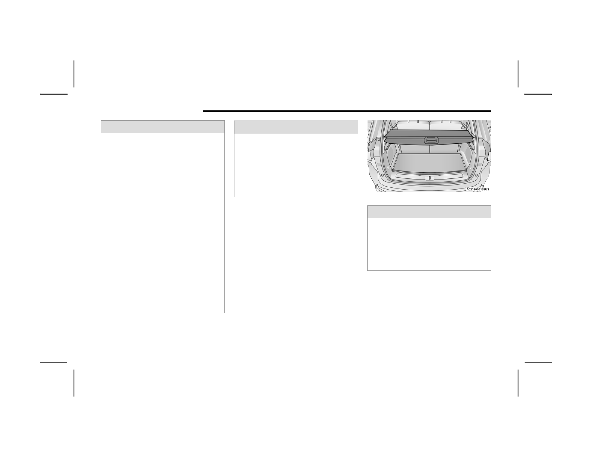
Retractable Cargo Area Cover — 

If Equipped

The purpose of this cover is for privacy, not to 

secure loads. It will not prevent cargo from shifting 

or protect passengers from loose cargo.
To cover the cargo area:
1. Grab the cover at the center handle and pull 

over the cargo area.

2. Insert the pins on the ends of the cover into the 

slots in the pillar trim cover.

3. The liftgate may be opened with the cargo 

cover in place.

Rear Cargo Cover

WARNING!

Cargo tie-downs are not safe anchors for a 

child seat tether strap. In a sudden stop or 

accident, a tie-down could pull loose and allow 

the child seat to come loose. A child could be 

badly injured. Use only the anchors provided 

for child seat tethers.

To help protect against personal injury, 

passengers should not be seated in the rear 

cargo area. The rear cargo space is intended 

for load carrying purposes only, not for 

passengers, who should sit in seats and use 

seat belts.

The weight and position of cargo and 

passengers can change the vehicle center of 

gravity and vehicle handling. To avoid loss of 

control resulting in personal injury, follow these 

guidelines for loading your vehicle:

Do not carry loads that exceed the load limits 

described on the label attached to the left 

door or left door center pillar.

Always place cargo evenly on the cargo floor. 

Put heavier objects as low and as far forward 

as possible.

Place as much cargo as possible in front of the 

rear axle. Too much weight or improperly 

placed weight over or behind the rear axle can 

cause the vehicle to sway.

Do not pile luggage or cargo higher than the 

top of the seatback. This could impair visibility 

or become a dangerous projectile in a sudden 

stop or accident.

WARNING!

WARNING!

In a collision, a loose cargo cover in the vehicle 

could cause injury. It could fly around in a 

sudden stop and strike someone in the vehicle. 

Do not store the cargo cover on the cargo floor 

or in the passenger compartment. Remove the 

cover from the vehicle when taken from its 

mounting. Do not store it in the vehicle.

GETTING TO KNOW YOUR VEHICLE

93

Foldable Cargo Area Cover — If Equipped

The purpose of this cover is for privacy, not to 

secure loads. It will not prevent cargo from shifting 

or protect passengers from loose cargo.

Foldable Cargo Area Cover

To cover the cargo area:
1. Remove the folded cover from the storage 

pouch, and unfold using a twisting motion.

2. Insert the pins on the ends of the cover into the 

slots on each side of the pillar trim.

Step 2

3. Hook the straps to the outside post of the rear 

head restraint on each side.

Step 3

NOTE:

The liftgate may be opened with the cargo cover in 

place.

To store the foldable cargo area cover, reverse the 

installation steps and replace the cover into its 

storage pouch.

Folding The Cargo Cover

1 — Remove Cover From Vehicle
2 — Twist Cover
3 — Push Twisted Cover Inward
4 — Place Folded Cover In Pouch

WARNING!

In a collision, a loose cargo cover in the vehicle 

could cause injury. It could fly around in a 

sudden stop and strike someone in the vehicle. 

Do not store the cargo cover on the cargo floor 

or in the passenger compartment. Remove the 

cover from the vehicle when taken from its 

mounting. Do not store it in the vehicle.

2

94

GETTING TO KNOW YOUR VEHICLE


(Continued)

ROOF LUGGAGE RACK — IF EQUIPPED 

The crossbars and siderails are designed to carry 

loads on vehicles equipped with a luggage rack. 

The load must not exceed 150 lb (68 kg), and 

should be uniformly distributed over the luggage 

rack crossbars.

NOTE:

See an authorized dealer to order and install 

Mopar® crossbars built specifically for this roof 

rack system.
Distribute cargo weight evenly on the roof rack 

crossbars. The roof rack does not increase the 

total load carrying capacity of the vehicle. Be sure 

the total load of cargo inside the vehicle plus that 

on the external rack does not exceed the maximum 

vehicle load capacity. Place one crossbar in the 

forward position. Place the rear crossbar in one of 

the two rear optional positions based on the load 

being secured.
To move the crossbars, loosen the attachments, 

located at the upper edge of each crossbar, 

approximately eight turns using the anti-theft 

wrench provided with the Mopar® crossbars. 

Then, move the crossbar to the desired position, 

keeping the crossbars parallel to the rack frame. 

Once the crossbar is in the desired position, 

retighten with the wrench to lock the crossbar into 

position.

NOTE:

If any cargo (or any metallic object) is placed over 

the satellite radio antenna (if equipped), you may 

experience interruption of satellite radio reception. 

For improved satellite radio reception, place the 

rear crossbar in the forward of the two rear 

crossbar positions.

WARNING!

Cargo must be securely tied down before driving 

your vehicle. Improperly secured loads can fly off 

the vehicle, particularly at high speeds, resulting 

in personal injury or property damage. Follow 

the roof rack cautions when carrying cargo on 

your roof rack.

CAUTION!

To prevent damage to the roof of your vehicle, 

do not carry any loads on the roof rack without 

the crossbars installed. The load should be 

secured and placed on top of the crossbars, 

not directly on the roof. If it is necessary to 

place the load on the roof, place a blanket or 

some other protection between the load and 

the roof surface.

To avoid damage to the roof rack and vehicle, 

do not exceed the maximum roof rack load 

capacity of 150 lb (68 kg). Always distribute 

heavy loads as evenly as possible and secure 

the load appropriately.

Long loads which extend over the windshield, 

such as wood panels or surfboards, or loads 

with large frontal area should be secured to 

both the front and rear of the vehicle.

Travel at reduced speeds and turn corners 

carefully when carrying large or heavy loads 

on the roof rack. Wind forces, due to natural 

causes or nearby truck traffic, can add sudden 

upward lift to a load. This is especially true on 

large flat loads and may result in damage to 

the cargo or your vehicle.

The use of vehicle systems that would adjust 

the ride heights (such as Selec-Terrain modes 

Rock or Mud) is not recommended when using 

the Roof Luggage Rack to carry a load.

CAUTION!

95

GETTING TO KNOW YOUR INSTRUMENT PANEL

INSTRUMENT CLUSTER

Holding the OK button on the Instrument Cluster Display controls located on the steering wheel will allow you to change your display from Digital to Analog.

3

96

GETTING TO KNOW YOUR INSTRUMENT PANEL


I

NSTRUMENT

 C

LUSTER

 D

ESCRIPTIONS

1. Speedometer

Indicates vehicle speed.

2. Temperature Gauge

The temperature gauge shows engine 

coolant temperature. Any reading within the 

normal range indicates that the engine 

cooling system is operating satisfactorily.

The pointer will likely indicate a higher 

temperature when driving in hot weather, 

up mountain grades, or when towing a 

trailer. It should not be allowed to exceed 

the upper limits of the normal operating 

range.

3. Tachometer

Indicates the engine speed in revolutions 

per minute (RPM x 1000).

4. Fuel Gauge

The pointer shows the level of fuel in the 

fuel tank when the Keyless Push Button 

Ignition is in the ON/RUN position.

 The fuel pump symbol points to 

the side of the vehicle where the 

fuel door is located.

NOTE:

The Instrument Cluster Warning Indicators will illu

-

minate briefly for a bulb check when the ignition is 

first cycled.

WARNING!

A hot engine cooling system is dangerous. You or 

others could be badly burned by steam or boiling 

coolant. It is recommended to call an authorized 

dealer for service if your vehicle overheats  

Ú

page 353.

CAUTION!

Driving with a hot engine cooling system could 

damage your vehicle. If the temperature gauge 

reads “H” pull over and stop the vehicle. Idle the 

vehicle with the air conditioner turned off until 

the pointer drops back into the normal range. If 

the pointer remains on the “H”, turn the engine 

off immediately and call an authorized dealer for 

service.

GETTING TO KNOW YOUR INSTRUMENT PANEL

97

INSTRUMENT CLUSTER

Holding the OK button on the Instrument Cluster Display controls located on the steering wheel will allow you to change your display from Analog to Digital.

3

98

GETTING TO KNOW YOUR INSTRUMENT PANEL


I

NSTRUMENT

 C

LUSTER

 D

ESCRIPTIONS

1. Tachometer

Indicates the engine speed in revolutions 

per minute (RPM x 1000).

2. Speedometer

Indicates vehicle speed.

3. Temperature Gauge

The temperature gauge shows engine 

coolant temperature. Any reading within the 

normal range indicates that the engine 

cooling system is operating satisfactorily.

The pointer will likely indicate a higher 

temperature when driving in hot weather, 

up mountain grades, or when towing a 

trailer. It should not be allowed to exceed 

the upper limits of the normal operating 

range.

4. Fuel Gauge

The pointer shows the level of fuel in the 

fuel tank when the Keyless Push Button 

Ignition is in the ON/RUN position.

 The fuel pump symbol points to 

the side of the vehicle where the 

fuel door is located.

NOTE:

The Instrument Cluster Warning Indicators will illu

-

minate briefly for a bulb check when the ignition is 

first cycled.

WARNING!

A hot engine cooling system is dangerous. You or 

others could be badly burned by steam or boiling 

coolant. It is recommended to call an authorized 

dealer for service if your vehicle overheats  

Ú

page 353.

CAUTION!

Driving with a hot engine cooling system could 

damage your vehicle. If the temperature gauge 

reads “H” pull over and stop the vehicle. Idle the 

vehicle with the air conditioner turned off until 

the pointer drops back into the normal range. If 

the pointer remains on the “H”, turn the engine 

off immediately and call an authorized dealer for 

service.

GETTING TO KNOW YOUR INSTRUMENT PANEL

99

INSTRUMENT CLUSTER DISPLAY

Your vehicle will be equipped with an instrument 

cluster display, which offers useful information to 

the driver. With the ignition in the OFF mode, 

opening/closing of a door will activate the display 

for viewing, and display the total miles, or 

kilometers, in the odometer. Your instrument 

cluster display is designed to display important 

information about your vehicle’s systems and 

features. Using a driver interactive display located 

on the instrument panel, your instrument cluster 

display can show you how systems are working and 

give you warnings when they are not. The steering 

wheel mounted controls allow you to scroll through 

the main menus and submenus. You can access 

the specific information you want and make 

selections and adjustments.

L

OCATION

 A

ND

 C

ONTROLS

Instrument Cluster Display/Controls Location

The system allows the driver to select information 

by pushing the following buttons mounted on the 

steering wheel:

Instrument Cluster Display Control Buttons

1 — Instrument Cluster Display Screen
2 — Instrument Cluster Display Controls

1 — Up Arrow Button
2 — OK Button
3 — Menu Button
4 — Left Arrow Button
5 — Down Arrow Button
6 — Right Arrow Button

3

100

GETTING TO KNOW YOUR INSTRUMENT PANEL


1. Up Arrow Button

Push and release the up   arrow button to 

scroll upward through the main menu.

2. OK Button

Push the OK button to access/select the infor

-

mation screens or submenu screens of a main 

menu item. Push and hold the OK button for 

one second to reset displayed/selected fea

-

tures that can be reset.

3. MENU Button

Push the MENU button to access/select the in

-

formation screens or submenu screens of the 

Home Screen display. Push and hold the OK 

button to enter edit mode.

4. Left Arrow Button

Push the left   arrow button to return to the 

main menu from an info screen or submenu 

item.

5. Down Arrow Button

Push and release the down   arrow button to 

scroll downward through the main menu.

6. Right Arrow Button

Push and release the right   arrow button to 

access the information screens or submenu 

screens of a main menu item.

Display Options
Holding OK will also allow you to change your 

display to Digital or Analog.

Digital theme will be the default theme

Menu screen times out after 10 seconds. Press 

OK to reactivate

Speedometer must always be present

Relevant warning notifications and other pop-up 

info will still be displayed in the main screen 

area (In this case the speed moves to the top)

Custom Tile Configuration
To customize the instrument cluster further, you 

are able to select up to five tiles to display 

information based on your needs.

Press the MENU button for the Home Screen 

display

Menu Button

Navigate Left or Right to highlight desired Tile

Press OK to select the tile and navigate to the 

selected submenu and press OK again to add 

your selection to your tile view

The main menu options are Main Menu, Vehicle 

Info, Navigation, Audio, and Off Road

The instrument cluster display is located in the 

center portion of the cluster and consist of multiple 

sections:

Main Screen — The inner ring of the display will 

illuminate in black under normal conditions, 

yellow for non critical warnings and red for crit

-

ical warnings

Submenu Dots — Whenever there are 

submenus available, the position within the 

submenus is shown here

GETTING TO KNOW YOUR INSTRUMENT PANEL

101

Reconfigurable Telltales/Information

Gear Selector Status (PRND)

Driver Interactive Display (Compass, Temp, 

Range to Empty, Trip A, Trip B, Average Fuel 

Economy, Current Fuel Economy and Time)

Air Suspension Status — If Equipped

Four Wheel Drive (4WD) Status — If Equipped

The instrument cluster display will normally display 

the main menu or the screens of a selected feature 

of the main menu. The main display area also 

displays pop-up messages that consist of 

approximately 60 possible warning or information 

messages. These pop-up messages fall into 

several categories:

Five Second Stored Messages 
When the appropriate conditions occur, this 

type of message takes control of the main 

display area for five seconds and then returns to 

the previous screen. Most of the messages of 

this type are then stored (as long as the condi

-

tion that activated it remains active) and can be 

reviewed from the “Messages” main menu item. 

Examples of this message type are “Right Front 

Turn Signal Lamp Out” and “Low Tire Pressure.”

Unstored Messages 
This message type is displayed indefinitely or 

until the condition that activated the message is 

cleared. Examples of this message type are 

“Turn Signal On” (if a turn signal is left on) and 

“Lights On” (if driver leaves the vehicle with the 

lights on).

Unstored Messages Until RUN 
These messages deal primarily with the Remote 

Start feature. This message type is displayed 

until the ignition is in the RUN state. Examples of 

this message type are “Remote Start Canceled - 

Door Ajar” and “Press Brake Pedal and Push 

Button to Start.”

Five Second Unstored Messages 
When the appropriate conditions occur, this 

type of message takes control of the main 

display area for five seconds and then returns to 

the previous screen. An example of this 

message type is “Automatic High Beams On.”

E

NGINE

 O

IL

 L

IFE

 R

ESET


Oil Change Required
Your vehicle is equipped with an engine oil change 

indicator system. The “Oil Change Required” 

message will display in the instrument cluster 

display for five seconds after a single chime has 

sounded, to indicate the next scheduled oil change 

interval. The engine oil change indicator system is 

duty cycle based, which means the engine oil 

change interval may fluctuate, dependent upon 

your personal driving style.
Unless reset, this message will continue to display 

each time the ignition is placed in the ON/RUN 

position. To turn off the message temporarily, push 

and release the OK or arrow buttons. To reset the 

oil change indicator system (after performing the 

scheduled maintenance), refer to the following 

procedure.

3

102

GETTING TO KNOW YOUR INSTRUMENT PANEL


Vehicles Equipped With Keyless Enter ‘n Go™ 

Ignition
Use the steering wheel instrument cluster display 

controls for the following procedure(s):
1. Without pressing the brake pedal, push the 

ENGINE START/STOP button and place the 

ignition in the ON/RUN position (do not start 

the engine).

2. Push and release the down   arrow button to 

scroll downward through the main menu to 

“Vehicle Info.”

3. Push and release the right   arrow button to 

access the “Oil Life” screen.

4. Push and hold the OK button to reset oil life. If 

conditions are met, the gauge and numeric 

display will update to show 100%. If conditions 

are not met a pop-up message of “To reset oil 

life engine must be off with ignition in run” will 

be displayed (for five seconds), and the user 

will remain at the Oil Life screen.

5. Push and release the up   or down   arrow 

button to exit the submenu screen.

NOTE:

If the indicator message illuminates when you start 

the vehicle, the oil change indicator system did not 

reset. If necessary, repeat this procedure.

Secondary Method Of Resetting Engine Oil Life
1. Without pressing the brake pedal, push the 

ENGINE START/STOP button and place the 

ignition to the ON/RUN position (do not start 

the engine).

2. Fully press the accelerator pedal, slowly, three 

times within 10 seconds.

3. Without pushing the brake pedal, push the 

ENGINE START/STOP button once to return the 

ignition to the OFF position.

NOTE:

If the indicator message illuminates when you start 

the vehicle, the oil change indicator system did not 

reset. If necessary, repeat this procedure.

GETTING TO KNOW YOUR INSTRUMENT PANEL

103

D

ISPLAY

 A

ND

 M

ESSAGES

Includes the following, but not limited to:

The Reconfigurable Telltales section is divided into the white or yellow telltales area on the left, and the green or red telltales area on the right.

Vehicle Speed is Too High to Shift to R

Front Seat Belts Unbuckled

Driver Seat Belt Unbuckled

Doors Open

Passenger Seat Belt Unbuckled

Traction Control Off

Vehicle Speed Too High To Shift to D

Washer Fluid Low

Oil Pressure Low

Hood Open

Oil Change Due

Fuel Low

Shift Not Allowed

Service Anti-lock Brake System

Service Electronic Throttle Control

Service Shifter

Service Power Steering

Cruise Off

Vehicle Speed is Too High to Shift to P

Cruise Ready

ACC Override

Service Transmission

Cruise Set To XXX mph or km/h

Cruise Set To XXX km/h

Liftgate Open

Tire Pressure Screen With Low Tire(s)

Service Tire Pressure System

Door Open

Park Brake Engaged

Brake Fluid Low

Service Air Bag Warning Light

Lights On

Engine Temperature Hot

Remote Start Disabled Start To Reset

Right Front Turn Signal Light Out

Right Rear Turn Signal Light Out

Service Air Bag System

Left Front Turn Signal Light Out

Left Rear Turn Signal Light Out

Remote Start Canceled Liftgate Open

Ignition or Accessory On

Vehicle Not In Park

Remote Start Canceled Time Expired

Remote Start Active Push Start Button

Remote Start Canceled Fuel Low

Remote Start Canceled Hood Open

Remote Start Canceled Door Open

Close Fuel Door

Check The Rear Seat

3

104

GETTING TO KNOW YOUR INSTRUMENT PANEL


I

NSTRUMENT

 C

LUSTER

 D

ISPLAY

 M

ENU


I

TEMS


The instrument cluster display can be used to view 

the main menu items for several features. Use the 
up   and down   arrow buttons to scroll through 

the driver interactive display menu options until 

the desired menu is reached.

NOTE:

Depending on the vehicle’s options, feature 

settings may vary.

Home Screen

Press the Menu button to display the Home 

Screen.
Push and release the left   or right   arrow 

button to highlight the desired selection. Push and 
release the OK button to select. Press the up   or 
down   arrow button to select a different screen 

within the selected category. If the Menu button is 

pressed in this view, the instrument cluster will 

return to the previously displayed screen.
Home Screen Options

Main Menu

Speedometer

Driver Assist — If Equipped

Night Vision — If Equipped

Vehicle Info

Fuel Economy

Gauge Summary

Oil Life

Tire Pressure

Stop/Start — If Equipped

Trip

Trip A

Trip B

Navigation

Map Display

Off Road

Terrain Status — If Equipped

Vehicle Dynamics

Pitch & Roll

Stored Messages

Messages

Settings

Screen Setup

Head Up Display — If Equipped

MAIN MENU

Push and release the up   or down   arrow 

button until the Drive menu title is displayed in the 

instrument cluster display.
Speedometer
Push and release the up   or down   arrow 

button until the Speedometer menu title is 

displayed in the instrument cluster display. Push 

and release the OK button to toggle units (mph or 

km/h) of the speedometer. Hold the OK button to 

toggle between Analog and Digital speedometer.
Night Vision — If Equipped

While viewing the Speedometer menu 
title, push and release the left   or 
right   arrow button until the Night 

Vision menu title is displayed in the instrument 

cluster display. Pedestrian/Animal icons will be 

displayed in the top left location  

Ú

page 180.

GETTING TO KNOW YOUR INSTRUMENT PANEL

105

Driver Assist — If Equipped
While viewing the Speedometer menu title, push 
and release the left  or right  arrow button 

until the Driver Assist menu title is displayed in the 

instrument cluster display. The Driver Assist 

screen indicates the current status of ACC, Active 

Lane Management and Active Driving Assist/

Assist+/Pilot. Push and release the OK button 

again to change between Zoomed In and Zoomed 

Out view (“Press OK to Zoom In” will display when 

in Zoomed Out view/“Press OK to Zoom Out” will 

display when in Zoomed In view).

VEHICLE INFO

Push and release the up   or down   arrow 

button until the Vehicle Info title is highlighted in 
the instrument cluster display. Push the left  or 
right  arrow button to scroll through the 

information submenus.
Fuel Economy 

Average Fuel Economy

Current Fuel Economy

Range To Empty

Press the OK button to reset the average fuel 

economy

NOTE:

The Range feature is not able to be reset through 

the instrument cluster display controls.
Gauge Summary

Coolant Temperature — If Equipped
Displays the current temperature of the coolant.

Transmission Temperature
Displays the actual transmission temperature.

Oil Temperature
Displays the actual oil temperature.

Oil Pressure
Displays the actual oil pressure.

Battery Voltage
Displays the current voltage level of the battery.

Oil Life

Displays the current oil life of the vehicle.

Tire Pressure Monitor System

If tire pressure is OK for all tires a vehicle icon is 

displayed with tire pressure values in each 

corner of the icon.

If one or more tires have low pressure, “Inflate 

Tire To XX” is displayed with the vehicle icon and 

the tire pressure values in each corner of the 

icon with the pressure value of the low tire are 

displayed in a different color than the other tire 

pressure value.

If the Tire Pressure system requires service, 

“Service Tire Pressure System” is displayed.

Tire Pressure is an information only function, and 

cannot be reset  

Ú

page 264.

Stop/Start Status — If Equipped

Display current status of Stop/Start system.

TRIP

Push and release the up   or down   arrow 

button until the Trip menu title is displayed in the 
instrument cluster display. Toggle the left   or 
right   arrow button to select Trip A or Trip B. The 

Trip information will display the following:

Distance – Shows the total distance (mi or km) 

traveled for Trip A or Trip B since the last reset.

Average Fuel Economy – Shows the average 

fuel economy (MPG or L/100 km or km/L) of 

Trip A or Trip B since the last reset.

Elapsed Time – Shows the total elapsed time of 

travel since Trip A or Trip B has been reset.

Hold the OK button to reset feature information.

3

106

GETTING TO KNOW YOUR INSTRUMENT PANEL


NAVIGATION — IF EQUIPPED

Push and release the up   or down   arrow 

button until the Navigation display title is 

highlighted in the instrument cluster display.

OFF ROAD

Push and release the up   or down   arrow 

button until the Off Road Menu title is highlighted. 
Push the left  or right   arrow button to scroll 

the submenus.

Terrain Status — If Equipped

Selec-Terrain Status

Air Suspension Status

Vehicle Dynamics

Wheel Articulation

Transfer Case Status — If Equipped

Steering Angle

Sway Bar Status — If Equipped

Axle Lock Status — If Equipped

Pitch And Roll

Vehicle Pitch

Vehicle Roll

AUDIO

Push and release the up   or down   arrow 

button until the Audio Menu title is highlighted in 

the instrument cluster display. This menu will 

display the audio source information, including the 

Song name, Artist name, and audio source with an 

accompanying graphic.

STORED MESSAGES

Push and release the up   or down   arrow 

button until the Messages Menu item is 

highlighted. This feature shows the number of 
stored warning messages. Pushing the left   or 
right   arrow button will allow you to see what the 

stored messages are.

SETTINGS

NOTE:

The Head Up Display (HUD) – If Equipped feature 

Settings are available at any vehicle speed  

Ú

page 107.

Screen Setup
Push and release the up   or down   arrow 

button until the Settings Menu title is highlighted in 

the instrument cluster display. Push and release 

the OK button to enter the submenus and follow 

the prompts on the screen as needed. The Settings 

feature allows you to change what information is 

displayed in the instrument cluster as well as the 

location that information is displayed.

Upper Left

None

Fuel Economy 

Current

Time

Outside Temp Trip B Distance Fuel Economy 

Average

Range To 

Empty (RTE)

Compass

Trip A Distance

Upper Right

None

Fuel Economy 

Current

Time

Outside Temp Trip B Distance Fuel Economy 

Average

Range To 

Empty (RTE)

Compass

Trip A Distance

GETTING TO KNOW YOUR INSTRUMENT PANEL

107

Current Gear

On

Off

Tachometer — Digital Theme Only

Show with Digital Theme

Hide with Digital Theme

Odometer

Show

Hide

NOTE:

Menus with (show/hide) can push the OK button to 

choose whether to show or hide this menu on the 

instrument cluster display.
Defaults (Restores All Settings To Default Settings)

Restore

Cancel

H

EAD

 U

P

 D

ISPLAY

 (HUD) — 

I

F

 E

QUIPPED


NOTE:

The HUD feature Settings are available at any 

vehicle speed.
Push and release the up   or down   arrow 

button until the Settings Menu icon/title is 

highlighted in the instrument cluster display. Push 
and release the left   or right   arrow button 

until the HUD Menu icon/title is highlighted in the 

instrument cluster display. Push and release the 
OK button to enter HUD. Use the up   or 
down   arrow button to select a setting, then 

push and release the OK button to adjust the 

setting.

ON/OFF

HUD ON/OFF

When “Display On” is selected, the HUD will 

display on the windshield. When it is not 

selected, it will not display on the windshield.

Content and Layout

Simple: Speed, Speed Limit

Standard: Speed, Speed Limit, Navigation

Favorite Menus

Main Menu

Trip

(Show/Hide)

Off Road 

(Show/Hide)

Vehicle Info

Navigation 

(Show/Hide)

Messages

Audio

(Show/Hide)

Settings

3


Content      ..     4      5      6      7     ..