Jeep Gladiator (2022 year). Manual in english - page 8


  Index      Manuals     Jeep Gladiator (2022 year). Manual in english


Search            copyright infringement  


Content      ..     6      7      8      9     ..


Jeep Gladiator (2022 year). Manual in english - page 8


GETTING TO KNOW YOUR INSTRUMENT PANEL

123

3
124

GETTING TO KNOW YOUR INSTRUMENT PANEL


I

NSTRUMENT

 C

LUSTER

 D

ESCRIPTIONS

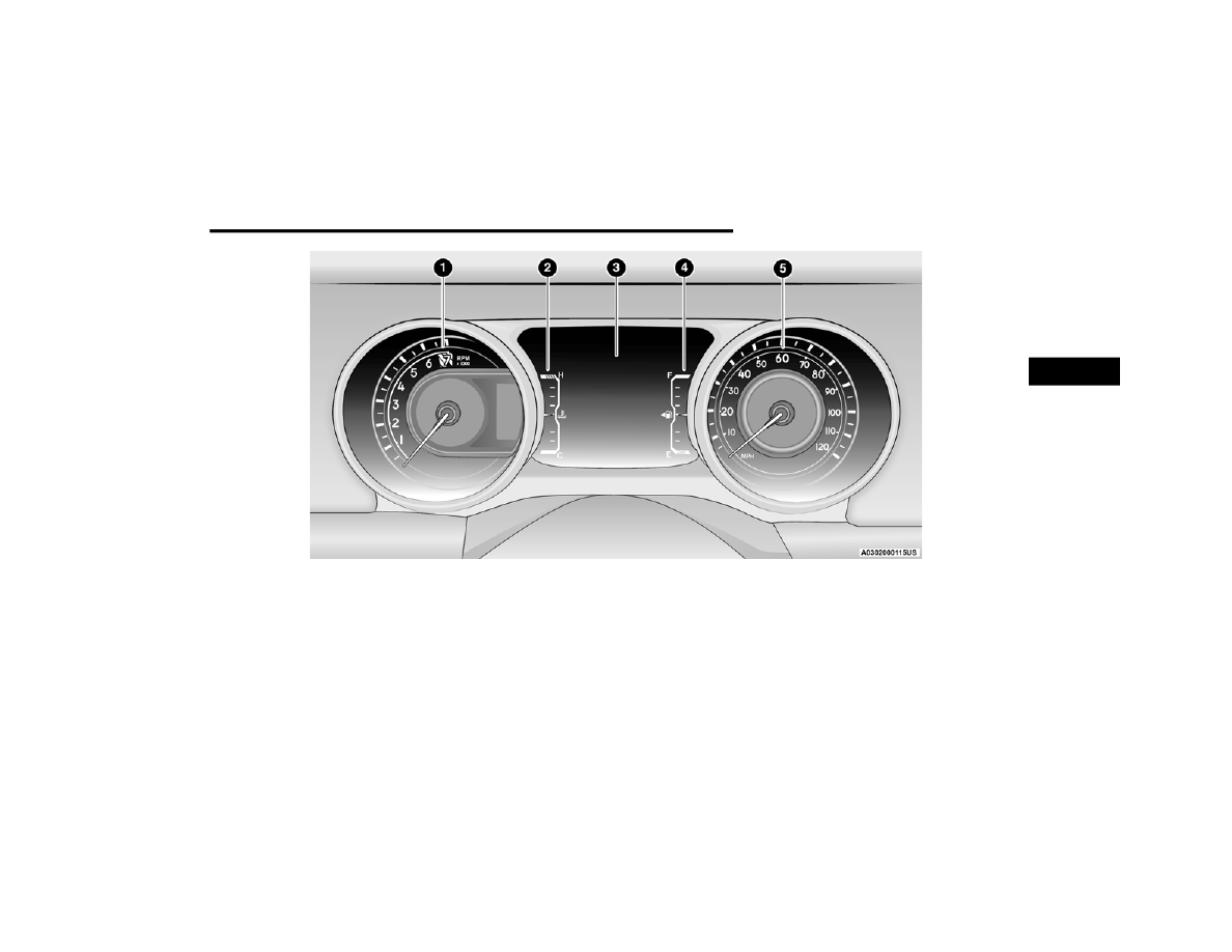
1. Tachometer

Indicates the engine speed in revolutions 

per minute (RPM x 1000).

2. Temperature Gauge

The temperature gauge shows engine 

coolant temperature. Any reading within the 

normal range indicates that the engine 

cooling system is operating satisfactorily.

The gauge pointer will likely indicate a 

higher temperature when driving in hot 

weather, up mountain grades, or when 

towing a trailer. It should not be allowed to 

exceed the upper limits of the normal oper

-

ating range.

3. Instrument Cluster Display

The instrument cluster display features a 

driver interactive display  

Ú

page 128.

4. Fuel Gauge

The pointer shows the level of fuel in the 

fuel tank when the ignition switch is in the 

ON/RUN position.

 The fuel pump symbol points to 

the side of the vehicle where the 

fuel filler door is located  

Ú

page 201.

5. Speedometer

Indicates vehicle speed.

CAUTION!

Do not operate the engine with the tachometer 

pointer in the red area. Engine damage will 

occur.

WARNING!

A hot engine cooling system is dangerous. You or 

others could be badly burned by steam or boiling 

coolant. It is recommended that you call an 

authorized dealer for service if your vehicle 

overheats.

CAUTION!

Driving with a hot engine cooling system could 

damage your vehicle. If the temperature gauge 

reads “H” pull over and stop the vehicle. Idle the 

vehicle with the air conditioner turned off until 

the pointer drops back into the normal range. If 

the pointer remains on the “H”, turn the engine 

off immediately and call an authorized dealer for 

service.

GETTING TO KNOW YOUR INSTRUMENT PANEL

125

DIESEL INSTRUMENT CLUSTERS

3

126

GETTING TO KNOW YOUR INSTRUMENT PANEL


GETTING TO KNOW YOUR INSTRUMENT PANEL

127

I

NSTRUMENT

 C

LUSTER

 D

ESCRIPTIONS

1. Tachometer

Indicates the engine speed in revolutions 

per minute (RPM x 1000).

2. Temperature Gauge

The temperature gauge shows engine 

coolant temperature. Any reading within the 

normal range indicates that the engine 

cooling system is operating satisfactorily.

The gauge pointer will likely indicate a 

higher temperature when driving in hot 

weather, up mountain grades, or when 

towing a trailer. It should not be allowed to 

exceed the upper limits of the normal oper

-

ating range.

3. Instrument Cluster Display

The instrument cluster display features a 

driver interactive display  

Ú

page 128.

4. Fuel Gauge

The pointer shows the level of fuel in the 

fuel tank when the ignition switch is in the 

ON/RUN position.

 The fuel pump symbol points to 

the side of the vehicle where the 

fuel filler door is located  

Ú

page 201.

5. Speedometer

Indicates vehicle speed.

CAUTION!

Do not operate the engine with the tachometer 

pointer in the red area. Engine damage will 

occur.

WARNING!

A hot engine cooling system is dangerous. You or 

others could be badly burned by steam or boiling 

coolant. It is recommended that you call an 

authorized dealer for service if your vehicle 

overheats.

CAUTION!

Driving with a hot engine cooling system could 

damage your vehicle. If the temperature gauge 

reads “H” pull over and stop the vehicle. Idle the 

vehicle with the air conditioner turned off until 

the pointer drops back into the normal range. If 

the pointer remains on the “H”, turn the engine 

off immediately and call an authorized dealer for 

service.

3

128

GETTING TO KNOW YOUR INSTRUMENT PANEL


INSTRUMENT CLUSTER DISPLAY

Your vehicle will be equipped with an instrument 

cluster display, which offers useful information to 

the driver. With the ignition in the OFF mode, 

opening/closing of a door will activate the display 

for viewing, and display the total miles (kilometers) 

in the odometer. Your instrument cluster display is 

designed to display important information about 

your vehicle’s systems and features. The driver 

interactive display, located in the instrument 

panel, indicates how systems are operating and 

gives you warnings when a system, or systems, 

needs your attention. The steering wheel mounted 

controls allow you to scroll through and enter the 

main menus and submenus. You can access the 

specific information you want to make selections 

and adjustments.

I

NSTRUMENT

 C

LUSTER

 D

ISPLAY


L

OCATION

 A

ND

 C

ONTROLS

The Instrument Cluster Display is located in the 

center of the instrument cluster. The display 

contains different areas of vehicle information.

Instrument Cluster Display Location

The top line where Reconfigurable Telltales, 

Compass Direction, Outside Temperature, Time, 

Range, Audio Info, MPG or Trip are displayed. 

This also displays the Speedometer which is an 

option for the upper center reconfigurable, but 

is not the default. Default setting is Menu Title.

The main display area where the menus and 

pop up messages are displayed.

The lower line where telltales, menu name and 

menu page are displayed.

The system allows the driver to select information 

by pushing the following buttons mounted on the 

steering wheel:

Instrument Cluster Display Control Buttons

Up   And Down   Arrow Buttons:
Using the up   or down   arrow button allow you 

to cycle through the Main Menu Items.
They allow you to change the Main Screen area 

and Menu Title area.

1 — Instrument Cluster Display Screen
2 — Instrument Cluster Display Controls

1 — Left Arrow Button
2 — Up Arrow Button
3 — Right Arrow Button
4 — Down Arrow Button
5 — OK Button

GETTING TO KNOW YOUR INSTRUMENT PANEL

129

Left   And Right   Arrow Buttons:
Using the left   or right   arrow button allow you 

to cycle through the submenu screens of the Main 

menu item.
OK Button
Push the OK button to access/select the 

information screens or submenu screens of a main 

menu item. To reset displayed/selected features 

push and hold the OK button for two seconds.

O

IL

 L

IFE

 R

ESET

 — I

F

 E

QUIPPED


Your vehicle may be equipped with an engine oil 

change indicator system. The “Oil Change 

Required” message will display in the instrument 

cluster display for five seconds after a single chime 

has sounded to indicate the next scheduled oil 

change interval. The engine oil change indicator 

system is duty cycle based, which means the 

engine oil change interval may fluctuate, 

dependent upon your personal driving style.
Unless reset, this message will continue to display 

each time you place the ignition in the ON/RUN 

position. To turn off the message temporarily, push 

and release the OK button. To reset the oil change 

indicator system (after performing the scheduled 

maintenance), refer to the following procedure.

Oil Life Reset
1. Without pushing the brake pedal, place the 

ignition in the ON/RUN mode (do not start the 

engine).

2. Navigate to "Oil Life" submenu in "Vehicle Info" 

in the instrument cluster display.

3. Push and hold the OK button until the gauge 

resets to 100%.

Secondary Method For Oil Change Reset 

Procedure
1. Without pushing the brake pedal, place the 

ignition in the ON/RUN position (do not start 

the engine).

2. Fully press the accelerator pedal, slowly, three 

times within ten seconds.

3. Without pushing the brake pedal, place the 

ignition in the OFF position.

NOTE:

If the indicator message illuminates when you start 

the vehicle, the oil change indicator system did not 

reset. If necessary, repeat this procedure.

O

FF

 R

OAD

+ D

ISPLAY

 — I

F

 E

QUIPPED

When the Off Road+ button is pushed in the switch 

bank, the Instrument Cluster Display will begin to 

show messages related to the feature. Depending 

on the Four Wheel Drive mode in use, the 

messages will differ, and after five seconds, all 

messages will clear from the display. The 

messages are as follows:

2H: Off Road+ Unavailable, Shift to 4WD

4H: 4WD High Off Road+ Active

4L: 4WD Low Off Road+ Active

Adaptive Cruise Control (ACC) and Cruise Control 

are not available when using Off Road+. If either 

option is selected, a dedicated message will 

display indicating that the features are not usable 

concurrently. Messages are as follows:

4H: Cruise Control — Cruise Control Unavailable 

in Off Road+

4H: Adaptive Cruise Control — Adaptive Cruise 

Control (ACC) Unavailable in Off Road+

4L: Cruise Control — Cruise Control Unavailable 

in 4WD Low

4L: Adaptive Cruise Control — Adaptive Cruise 

Control (ACC) Unavailable in 4WD Low

3

130

GETTING TO KNOW YOUR INSTRUMENT PANEL


NOTE:

The behavior of Electronic Stability Control while in 

Off Road+ varies depending on the 4WD status. If 

the vehicle is in 4WD High, Traction Control is auto

-

matically turned off. Also, holding the ESC OFF 

button for five seconds will turn off ESC. In 4WD 

Low, Electronic Stability Control automatically 

shuts off regardless of the Off Road Status.

I

NSTRUMENT

 C

LUSTER

 D

ISPLAY


S

ELECTABLE

 I

TEMS

The instrument cluster display can be used to view 

the following main menu items:

NOTE:

Depending on the vehicles options, feature 

settings may vary.

I

NSTRUMENT

 C

LUSTER

 D

ISPLAY

 M

ENU


I

TEMS

NOTE:

Depending on the vehicle’s options, feature 

settings may vary.

Speedometer

Push and release the up   or down   arrow 

button until the speedometer menu icon is 

displayed in the instrument cluster display. Push 

and release the OK button to toggle between mph 

and km/h.

Vehicle Info

Push and release the up   or down   arrow 

button until the Vehicle Info menu icon is displayed 

in the instrument cluster display. Push and release 
the left   or right   arrow button to scroll 

through the information submenus and push and 

release the OK button to select or reset the 

resettable submenus.

Off Road — If Equipped

Push and release the up   or down   arrow 

button until the Off Road menu icon is displayed in 

the instrument cluster display. Push and release 
the left   or right   arrow button to scroll 

through the information submenus.
Drivetrain

Front Wheel Angle: displays the graphical and 

numerical value of calculated average front 

wheel angle from the steering wheel orientation.

Transfer Case Lock Status: displays “Lock” 

graphic only during 4WD High, 4WD High Part 

Time or 4WD Low status.

Axle Lock And Sway Bar Status (if equipped): 

displays front and rear or rear only axle locker 

graphic, and sway bar connection graphic with 

text message (connected or disconnected).

• Speedometer • Driver Assist 

— If Equipped

• Messages

• Vehicle Info

• Trip Info

• Screen Setup

• Fuel Economy • Stop/Start
• Off Road — If 

Equipped

• Audio

Tire Pressure

Coolant Tempera

-

ture

Transmission 

Temperature — Auto

-

matic Transmission 

Only

Oil Pressure

Oil Temperature

Oil Life

Battery Voltage

Diesel Exhaust Fluid 

Level — If Equipped

GETTING TO KNOW YOUR INSTRUMENT PANEL

131

Pitch And Roll
Displays the pitch and roll of the vehicle in the 

graphic with the angle number on the screen.

NOTE:

When vehicle speed becomes too high to display 

the pitch and roll, “- -” will display in place of the 

numbers, and the graphic will be grayed out. A 

message indicating the necessary speed for the 

feature to become available will also display.

Driver Assist — If Equipped

The Driver Assist menu displays the status of the 

ACC system.
Push and release the up   or down   arrow 

button until the Driver Assist menu is displayed in 

the instrument cluster display.
Adaptive Cruise Control (ACC) Feature — 

If Equipped
The instrument cluster display displays the current 

ACC system settings. The information displayed 

depends on ACC system status.
Push the ACC ON/OFF button (located on the 

steering wheel) until one of the following displays 

in the instrument cluster display:
Adaptive Cruise Control Off
When ACC is deactivated, the display will read 

“Adaptive Cruise Control Off.”

Adaptive Cruise Control Ready
When ACC is activated but the vehicle speed 

setting has not been selected, the display will read 

“Adaptive Cruise Control Ready.”
Push the SET + or the SET - button (located on the 

steering wheel), and the following will display in the 

instrument cluster display.
ACC SET
When ACC is set, the set speed will display in the 

instrument cluster.
The ACC screen may display once again if any ACC 

activity occurs, which may include any of the 

following:

System Cancel

Driver Override

System Off

ACC Proximity Warning

ACC Unavailable Warning

NOTE:

The instrument cluster display will return to the last 

display selected after five seconds of no ACC 

display activity  

Ú

page 184.

Fuel Economy

Push and release the up   or down   arrow 

button until the Fuel Economy icon is highlighted in 

the instrument cluster display. Push and hold the 

OK button to reset average fuel economy feature.

Toggle left   or right   to select a display with or 

without Current Fuel Economy Information.

Range – The display shows the estimated 

distance (mi or km) that can be traveled with the 

fuel remaining in the tank. When the Range 

value is less than 10 miles (16 km), the Range 

display will change to a “LOW” message. Adding 

a significant amount of fuel to the vehicle will 

turn off the “LOW” message and a new Range 

value will display. Range cannot be reset 

through the OK button.

NOTE:

Significant changes in driving style or vehicle 

loading will greatly affect the actual drivable 

distance of the vehicle, regardless of the Range 

displayed value.

Average – The display shows the average fuel 

economy (MPG, L/100km, or km/L) since the 

last reset.

Current – The display shows the current fuel 

economy (MPG, L/100km, or km/L) while 

driving.

Trip

Push and release the up   or down   arrow 

button until the Trip icon/title is highlighted in the 

instrument cluster display, then push and release 
the left   or right   arrow button to select Trip A 

or Trip B.

3

132

GETTING TO KNOW YOUR INSTRUMENT PANEL


The Trip A and Trip B information will display the 

following:

Distance

Average Fuel Economy

Elapsed Time

Hold the OK button to reset all the information.

Stop/Start — If Equipped

Push and release the up   or down   arrow 

button until the Stop/Start icon/title is highlighted 

in the instrument cluster display. The screen will 

display the Stop/Start status.

Audio

Push and release the up   or down   arrow 

button until the Stop/Start icon/title is highlighted 

in the instrument cluster display. The screen will 

display the Stop/Start status.
Phone Call Status
When a call is incoming, a Phone Call Status 

pop-up will display on the screen. The pop-up will 

remain until the phone is answered or ignored.

NOTE:

The call status will temporarily replace the 

previous media source information displayed on 

the screen. When the pop-up is no longer 

displayed, the display will return to the last used 

screen.

Stored Messages

Push and release the up   or down   arrow 

button until the Messages Menu item is 

highlighted. This feature shows the number of 

stored warning messages. Pushing the 
right   arrow button will allow you to see what the 

stored messages are.
When no messages are present, main menu icon 

will be a closed envelope, and “No Stored 

Messages” will display.

Screen Setup

NOTE:

The Screen Setup feature can only be used while 

the vehicle is not in motion.
Push and release the up   or down   arrow 

button until the Screen Setup Menu Icon/Title is 

highlighted in the instrument cluster display. Push 

and release the OK button to enter the submenus 

and follow the prompts on the screen as needed. 

The Screen Setup feature allows you to change 

what information is displayed in the instrument 

cluster as well as the location in which that 

information is displayed.

Screen Setup Driver Selectable Items

Upper Left

None

Time

Current Econ

Compass

Range to 

Empty

Trip A Distance

Outside Temp Average Econ

Trip B Distance

Upper Right

None

Time

Current Econ

Compass

Range to 

Empty

Trip A Distance

Outside Temp Average Econ

Trip B Distance

Upper Center

None

Time

Current Econ

Compass

Range to 

Empty

Trip A Distance

Audio

Average Econ

Trip B Distance

Outside Temp Menu Title

Speedometer

GETTING TO KNOW YOUR INSTRUMENT PANEL

133

Gear Display — If Equipped

Full

Single

Current Gear

Off

On

Odometer

Show

Hide

Defaults

Cancel

Restore

B

ATTERY

 S

AVER

 O

N

, B

ATTERY


S

AVER

 M

ODE

 M

ESSAGE

, A

ND


E

LECTRICAL

 L

OAD

 R

EDUCTION

 A

CTIONS


(I

F

 E

QUIPPED

)

This vehicle is equipped with an Intelligent Battery 

Sensor (IBS) to perform additional monitoring of 

the electrical system and status of the vehicle 

battery.
In cases when the IBS detects charging system 

failure, or the vehicle battery conditions are 

deteriorating, electrical load reduction actions will 

take place to extend the driving time and distance 

of the vehicle. This is done by reducing power to or 

turning off non-essential electrical loads.
Load reduction is only active when the engine is 

running. It will display a message if there is a risk 

of battery depletion to the point where the vehicle 

may stall due to lack of electrical supply, or will not 

restart after the current drive cycle.
When load reduction is activated, the message 

“Battery Saver On Some Systems May Have 

Reduced Power” will appear in the instrument 

cluster.

These messages indicate the vehicle battery has a 

low state of charge and continues to lose electrical 

charge at a rate that the charging system cannot 

sustain.

NOTE:

The charging system is independent from load 

reduction. The charging system performs a diag

-

nostic on the charging system continuously.

If the Battery Charge Warning Light is on it may 

indicate a problem with the charging system  

Ú

page 139.

The electrical loads that may be switched off 

(if equipped), and vehicle functions which can be 

affected by load reduction:

Heated Seat/Vented Seats/Heated Wheel

Rear Defroster And Heated Mirrors

HVAC System

115 Volt AC Power Inverter System

Audio and Telematics System

Favorite Menus

Speedometer

Vehicle Info

Off Road — If 

Equipped 

(show/hide)

Driver Assist — 

If Equipped 

(show/hide)

Fuel Economy 

(show/hide)

Trip Info 

(show/hide)

Stop / Start — 

If Equipped

Audio (show/

hide)

Messages

Screen Setup

Vehicle 

Settings — If 

Equipped

3

134

GETTING TO KNOW YOUR INSTRUMENT PANEL


Loss of battery charge may indicate one or more of 

the following conditions:

The charging system cannot deliver enough 

electrical power to the vehicle system because 

the electrical loads are larger than the capability 

of the charging system. The charging system is 

still functioning properly.

Turning on all possible vehicle electrical loads 

(e.g. HVAC to max settings, exterior and interior 

lights, overloaded power outlets +12 Volt, 

115 Volt AC, USB ports) during certain driving 

conditions (city driving, towing, frequent stop

-

ping).

Installing options like additional lights, upfitter 

electrical accessories, audio systems, alarms 

and similar devices.

Unusual driving cycles (short trips separated by 

long parking periods).

The vehicle was parked for an extended period 

of time (weeks, months).

The battery was recently replaced and was not 

charged completely.

The battery was discharged by an electrical load 

left on when the vehicle was parked.

The battery was used for an extended period 

with the engine not running to supply radio, 

lights, chargers, +12 Volt portable appliances 

like vacuum cleaners, game consoles and 

similar devices.

What to do when an electrical load reduction 

action message is present (“Battery Saver On” or 

“Battery Saver Mode”)
During a trip:

Reduce power to unnecessary loads if possible:

Turn off redundant lights 

(interior or exterior)

Check what may be plugged in to power 

outlets +12 Volt, 115 Volts AC, USB ports

Check HVAC settings (blower, temperature)

Check the audio settings (volume)

After a trip:

Check if any aftermarket equipment was 

installed (additional lights, upfitter electrical 

accessories, audio systems, alarms) and review 

specifications if any (load and ignition off draw 

currents).

Evaluate the latest driving cycles (distance, 

driving time and parking time).

The vehicle should have service performed if 

the message is still present during consecutive 

trips and the evaluation of the vehicle and 

driving pattern did not help to identify the cause.

D

IESEL

 D

ISPLAYS

When the appropriate conditions exist, the 

following messages display in the instrument 

cluster display:

Exhaust Filter Nearing Full Safely Drive at 

Consistent Speeds to Clear

Exhaust Filter Full – Power Reduced See Dealer

Exhaust System Service Required – See Dealer

Exhaust System – Filter XX% Full Service 

Required See Dealer

Exhaust System Regeneration in Process 

Continue Driving

Exhaust System – Regeneration Completed

D

IESEL

 P

ARTICULATE

 F

ILTER

 (DPF) 

M

ESSAGES

This engine meets all required diesel engine 

emissions standards. To achieve these emissions 

standards, your vehicle is equipped with a 

state-of-the-art engine and exhaust system. These 

systems are seamlessly integrated into your 

vehicle and managed by the Powertrain Control 

Module (PCM). The PCM manages engine 

combustion to allow the exhaust system’s catalyst 

to trap and burn Particulate Matter (PM) 

pollutants, with no input or interaction on your part.

GETTING TO KNOW YOUR INSTRUMENT PANEL

135

Your vehicle has the ability to alert you to 

additional maintenance required on your vehicle or 

engine. Refer to the following messages that may 

be displayed on your instrument cluster display:

Exhaust Filter Nearing Full Safely Drive at 

Consistent Speeds to Clear — This message will 

be displayed if the exhaust particulate filter 

reaches 80% of its maximum storage capacity. 

Under conditions of exclusive short duration 

and low speed driving cycles, your diesel engine 

and exhaust after-treatment system may never 

reach the conditions required to cleanse the 

filter to remove the trapped PM. If this occurs, 

the “Exhaust Filter XX% Full Safely Drive at 

Highway Speeds to Remedy” message will be 

displayed. If this message is displayed, you will 

hear one chime to assist in alerting you of this 

condition. By simply driving your vehicle at 

highway speeds for up to 20 minutes, you can 

remedy the condition in the particulate filter 

system and allow your diesel engine and 

exhaust after-treatment system to cleanse the 

filter to remove the trapped PM and restore the 

system to normal operating condition.

Exhaust System Regeneration in Process 

Continue Driving — This message indicates that 

the DPF is self-cleaning. Maintain your current 

driving condition until regeneration is 

completed.

Exhaust System — Regeneration Completed — 

This message indicates that the DPF 

self-cleaning is completed. If this message is 

displayed, you will hear one chime to assist in 

alerting you of this condition.

Exhaust System Service Required — See Dealer 

— This message indicates regeneration has 

been disabled due to a system malfunction. At 

this point the engine Powertrain Control Module 

(PCM) will register a fault code, the instrument 

panel will display a Malfunction Indicator Light 

(MIL) light.

Exhaust Filter Full — Power Reduced 

See Dealer — This message indicates the PCM 

has derated the engine to limit the likelihood of 

permanent damage to the after-treatment 

system. If this condition is not corrected and a 

dealer service is not performed, extensive 

exhaust after-treatment damage can occur. To 

correct this condition it will be necessary to have 

your vehicle serviced by an authorized dealer.

WARNING!

A hot exhaust system can start a fire if you park 

over materials that can burn, such as grass or 

leaves, and those items coming into contact with 

your exhaust system. Do not park or operate 

your vehicle in areas where your exhaust system 

can contact anything that can burn.

CAUTION!

The engine may be switched off even if the 

warning light is on: repeated interruptions of the 

regeneration process could cause an early 

deterioration of engine oil. For this reason it is 

always advisable to wait for the symbol to go off 

before turning off the engine, following the 

instructions above. Do not complete the DPF 

regeneration process when the vehicle is 

stopped.

CAUTION!

See an authorized dealer, as damage to the 

exhaust system could occur soon with continued 

operation.

3

136

GETTING TO KNOW YOUR INSTRUMENT PANEL


NOTE:

Failing to follow the oil change indicator, changing 

your oil and resetting the oil change indicator by 

0 miles (0 kilometers) remaining will prevent the 

diesel exhaust filter from performing its cleaning 

routine. This will shortly result in a Malfunction 

Indicator Light (MIL) and reduced engine power. 

Only an authorized dealer will be able to correct 

this condition.

F

UEL

 S

YSTEM

 M

ESSAGES

The following chart contains a list of different 

messages that may appear in the instrument 

cluster, depending on different system or fuel 

conditions. Use the descriptions to interpret what 

the message means and determine the best action 

to take.

CAUTION!

See an authorized dealer, as damage to the 

exhaust system could occur soon with continued 

operation.

MESSAGE

DESCRIPTION

Diesel Emissions Additive AdBlue® (UREA) Warning Messages:

Low Diesel Emissions Additive 

AdBlue® (UREA) Level Warning

The first low level warning will be given at around a 1,490 miles (2,400 km) range, and is determined according to the 

current consumption rate. The “UREA Low Level” warning light and message will display on the instrument panel. The 

UREA low level warning light will remain lit until the AdBlue® (UREA) tank is topped up with at least 1.32 gallons 

(5 Liters) of UREA.
If the level is not resolved, an additional warning appears whenever a certain threshold is reached until it will no 

longer be possible to start the engine.
When 125 miles (200 km) are remaining before the AdBlue® (UREA) tank is empty, a message will appear on the 

instrument panel, accompanied by a buzzer sound. When the range is at 0, the display will show a dedicated message 

(if equipped). In this case, the engine will not restart.
It will be possible to restart the engine again as soon as AdBlue® (UREA) is added; the minimum amount required is 

1.32 gallons (5 Liters). Fill the AdBlue® (UREA) tank as soon as possible with at least 1.32 gallons (5 Liters) of UREA. 

If filling is completed with autonomy tank AdBlue® (UREA) to zero, it could be possible to wait 2 minutes before 

starting the vehicle.

NOTE:

When the AdBlue® (UREA) tank is empty, and the vehicle is stopped, it is no longer possible to restart the vehicle until 

a minimum of 1.32 gallons (5 Liters) of AdBlue® (UREA) is added to the AdBlue® (UREA) tank.

GETTING TO KNOW YOUR INSTRUMENT PANEL

137

Diesel Emissions Additive AdBlue® (UREA) Fault Warning Messages:

Engine Will Not Restart Service 

AdBlue® System See Dealer

This message will display if the AdBlue® (UREA) system issue detected is not serviced during the allowed period. Your 

engine will not restart unless your vehicle is serviced by an authorized dealer. If the level is not resolved, an additional 

warning appears whenever a certain threshold is reached until it will no longer be possible to start the engine. When 

125 miles (200 km) are remaining before the AdBlue® tank is empty, a message will appear on the instrument panel, 

accompanied by a buzzer sound.

Engine Will Not Start Service 

AdBlue® System See Dealer

NOTE:

The display may take up to five seconds to update after adding 2 gallons (7.5 Liters) or more of AdBlue® (UREA) to 

the AdBlue® (UREA) tank. If you have a fault related to the AdBlue® (UREA) system, the display may not update to 

the new level. See an authorized dealer for service.

AdBlue® freezes at temperatures lower than 12°F (-11°C). If the car stands for a long time at this temperature, 

refilling could be difficult. For this reason, it is advised to park the vehicle in a garage and/or heated environment, 

and wait for the AdBlue® (UREA) to return to liquid state before topping up.

Gasoline Particulate Filter (GPF) System Messages — If Equipped:

Exhaust System Service Required

The engine control unit has detected an issue with the gasoline particulate filter system. See an authorized dealer.

Exhaust System Regeneration in 

Process Continue Driving

The regeneration procedure is controlled automatically by the engine control unit according to the filter conditions and 

car use conditions. The following may occur during regeneration: increased levels of Noise Vibration and Harshness 

(NVH) and reduced engine performance. The driver should continue driving normally. This message will continue to 

appear until regeneration is complete.

Exhaust System Regeneration 

Complete

The exhaust gas filter regeneration has been completed. This message will briefly appear.

MESSAGE

DESCRIPTION

3

138

GETTING TO KNOW YOUR INSTRUMENT PANEL


WARNING LIGHTS AND MESSAGES

The warning/indicator lights will illuminate in the 

instrument panel together with a dedicated 

message and/or acoustic signal when applicable. 

These indications are indicative and precautionary 

and as such must not be considered as exhaustive 

and/or alternative to the information contained in 

the Owner’s Manual, which you are advised to read 

carefully in all cases. Always refer to the 

information in this chapter in the event of a failure 

indication. All active telltales will display first if 

applicable. The system check menu may appear 

different based upon equipment options and 

current vehicle status. Some telltales are optional 

and may not appear.

R

ED

 W

ARNING

 L

IGHTS

Air Bag Warning Light

This warning light will illuminate to 

indicate a fault with the air bag, and will 

turn on for four to eight seconds as a bulb 

check when the ignition is placed in the 

ON/RUN or ACC/ON/RUN position. This light will 

illuminate with a single chime when a fault with the 

air bag has been detected, it will stay on until the 

fault is cleared. If the light is not on during startup, 

stay on, or turns on while driving, have the system 

inspected at an authorized dealer as soon as 

possible.

Brake Warning Light

This warning light monitors various brake 

functions, including brake fluid level and 

parking brake application. If the brake 

light turns on it may indicate that the 

parking brake is applied, that the brake fluid level 

is low, or that there is a problem with the Anti-Lock 

Brake System reservoir.
If the light remains on when the parking brake has 

been disengaged, and the fluid level is at the full 

mark on the master cylinder reservoir, it indicates 

a possible brake hydraulic system malfunction or 

that a problem with the Brake Booster has been 

detected by the Anti-Lock Brake System (ABS) / 

Electronic Stability Control (ESC) system. In this 

case, the light will remain on until the condition has 

been corrected. If the problem is related to the 

brake booster, the ABS pump will run when 

applying the brake, and a brake pedal pulsation 

may be felt during each stop.
The dual brake system provides a reserve braking 

capacity in the event of a failure to a portion of the 

hydraulic system. A leak in either half of the dual 

brake system is indicated by the Brake Warning 

Light, which will turn on when the brake fluid level 

in the master cylinder has dropped below a 

specified level.
The light will remain on until the cause is corrected.

NOTE:

The light may flash momentarily during sharp 

cornering maneuvers, which change fluid level 

conditions. The vehicle should have service 

performed, and the brake fluid level checked.
If brake failure is indicated, immediate repair is 

necessary.

Vehicles equipped with the Anti-Lock Brake System 

(ABS) are also equipped with Electronic Brake 

Force Distribution (EBD). In the event of an EBD 

failure, the Brake Warning Light will turn on along 

with the ABS Light. Immediate repair to the ABS 

system is required.
Operation of the Brake Warning Light can be 

checked by turning the ignition switch from the OFF 

position to the ON/RUN position. The light should 

illuminate for approximately two seconds. The light 

should then turn off unless the parking brake is 

applied or a brake fault is detected. If the light does 

not illuminate, have the light inspected by an 

authorized dealer.

WARNING!

Driving a vehicle with the red brake light on is 

dangerous. Part of the brake system may have 

failed. It will take longer to stop the vehicle. You 

could have a collision. Have the vehicle checked 

immediately.


Content      ..     6      7      8      9     ..