Jeep Gladiator (2022 year). Manual in english - page 7
 

  Index      Manuals     Jeep Gladiator (2022 year). Manual in english


Search            copyright infringement  


Content      ..     5      6      7      8     ..


Jeep Gladiator (2022 year). Manual in english - page 7


GETTING TO KNOW YOUR VEHICLE

107

5. Repeat steps 3 and 4 on the other side of the 

vehicle.

NOTE:

The recommended torque specification for the 

front and rear door rail attachment bolts is 8.8 ft-lb 

(12 N·m).
6. Attach the rear clamp at the rear center of the 

Sunrider® top using the two provided rear 

clamp attachment bolts. Tighten with #40 Torx 

head driver until snug.

Rear Clamp Location

NOTE:

The recommended torque specification for the rear 

clamp attachment bolts is 3.7 ft-lb (5 N·m).
7. From inside the vehicle, lift and pull the 

Sunrider® top forward using the integrated 

handle on the front header of the top. 

Manually guide the top into the closed 

position.

Push Sunrider® Top Forward

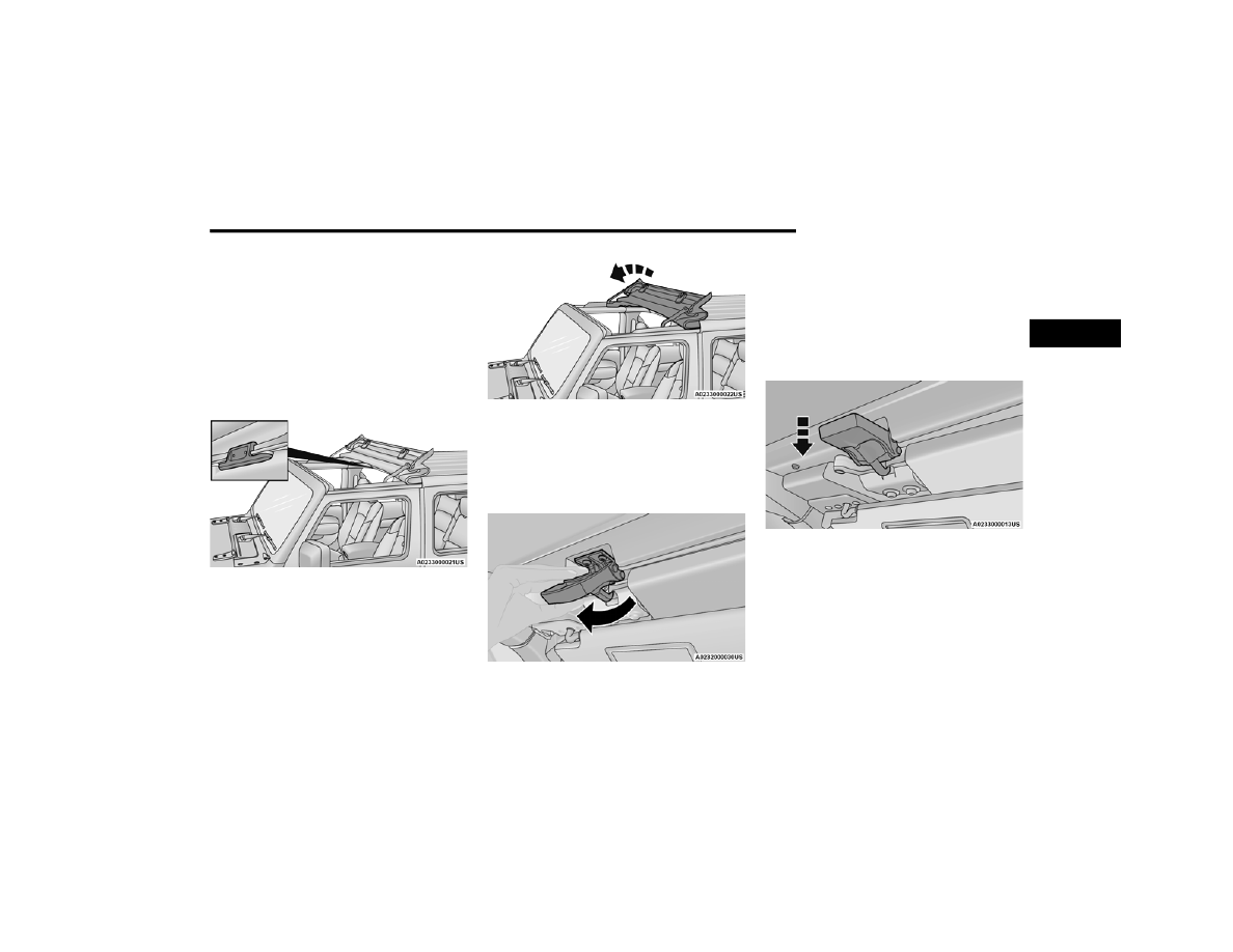
8. From inside the vehicle, pull the handle on the 

header latch downward to engage the hook 

into its receiver. Pull the handle back upward 

while squeezing the hook, locking the latch 

into place. Repeat on the other side.

Engage Both Header Latches

To Open The Sunrider® Top
To open the Sunrider® top, proceed as follows:
1. Fold both sun visors forward against the 

windshield.

2. Release the header latches from the crossbar 

by pulling the handle downward. Make sure 

the hook is disengaged from its receiver.

Release Both Header Latches

2

108

GETTING TO KNOW YOUR VEHICLE


3. From the front of the Sunrider® top, lift and 

push the top rearward to the Sunrider® 

position.

Sunrider® Position

4. Secure the top by using the two hook-and-loop 

fasteners provided with the Sunrider® kit, and 

wrap one around the side rails on each side of 

the Sunrider® top to hold it in place.

Hook-And-Loop Fastener Placement

DOOR FRAME — IF EQUIPPED WITH A 

SOFT TOP 

WARNING!

Do not drive your vehicle on public roads with 

the door frame(s) removed as you will lose the 

protection that they can provide. This proce

-

dure is furnished for use during off-road oper

-

ation only.

Do not drive your vehicle on public roads with 

the doors removed as you will lose the protec

-

tion that they can provide. This procedure is 

furnished for use during off-road operation 

only.

CAUTION!

Failure to follow these cautions may cause 

interior water damage, stains or mildew:

Opening a door or lowering a window while the 

top is wet may allow water to drip into the 

vehicle's interior.

Careless handling and storage of the remov

-

able door frame(s) may damage the seals, 

causing water to leak into the vehicle's inte

-

rior.

The door frame(s) must be positioned properly 

to ensure sealing. Improper installation can 

cause water to leak into the vehicle's interior.

GETTING TO KNOW YOUR VEHICLE

109

D

OOR

 F

RAME

 R

EMOVAL

NOTE:

The rear door frames must be removed first, 

followed by the front door frames.
1. Using the provided #T40 Torx head driver and 

ratchet, loosen the Torx head fasteners 

located on the underside of each door hinge 

(two per door), and remove the fasteners by 

pulling downward.

Step One

NOTE:

The fasteners will not fall out once completely 

loose, as they are held in place by design.

Step One

2. Lift the frame upward, removing it from the 

vehicle.

Step Two

3. Store the fasteners in a secure location.
4. Repeat the procedure on the front door frame.

D

OOR

 F

RAME

 I

NSTALLATION

1. Install the front door frame first.
2. Ensure the windshield is in the “up” position. 

Carefully place the front door frame in the 

rubber seal at the top of the windshield, and 

line up the holes for the Torx head fasteners 

(two for each door).

WARNING!

Do not drive your vehicle on public roads with 

the door and/or door frame(s) removed as you 

will lose the protection that they can provide. 

This procedure is furnished for use during 

off-road operation only.

2

110

GETTING TO KNOW YOUR VEHICLE


3. Swing the frame bracket around the side of the 

door frame, and insert the fasteners from 

underneath. Tighten with the #T40 Torx head 

driver until they are snug, being careful not to 

cross-thread the fasteners or overtighten. 

Refer to the following table for the appropriate 

torque specifications for the door frame 

fasteners.

Tighten Fasteners

4. Set the rear door frame pin into the hole on top 

of the body side, just behind the rear door 

opening.

5. Carefully position the top of the door frame 

onto the rear belt rail and the rear of the front 

door frame, making sure the rubber seals lay 

flat. Ensure the seals are installed correctly to 

avoid water leaks.

Step Five

Step Five

6. Insert the fasteners from underneath. Tighten 

with the #T40 Torx head driver until they are 

snug, being careful not to cross-thread the 

fasteners or overtighten. Refer to the previous 

table for the appropriate torque specifications 

for the door frame fasteners.

FOLDING WINDSHIELD 

The fold-down windshield on your vehicle is a 

structural element that can provide protection in 

some accidents. The windshield also provides 

protection against weather, road debris and 

intrusion of small branches and other objects.

Target Torque 

Specification 

For Torx 

Fasteners

Maximum

Minimum

44.2 in-lb 

(5 N·m)

53.1 in-lb 

(6 N·m)

35.4 in-lb 

(4 N·m)

CAUTION!

Do not overtighten Torx fasteners. You can strip 

the fasteners if they are overtightened.

GETTING TO KNOW YOUR VEHICLE

111

(Continued)

Do not drive your vehicle on-road with the 

windshield down, as you lose the protection this 

structural element provides.
If required for certain off-road uses, the windshield 

can be folded down. However, the protection 

afforded by the windshield is then lost. If you fold 

down the windshield, drive slowly and cautiously. It 

is recommended that the speed of the vehicle be 

limited to 10 mph (16 km/h), with low range 

operation preferred if you are driving off-road with 

the windshield folded down.
Raise the windshield as soon as the task that 

required its removal is completed and before you 

return to on-road driving. Both you and your 

passengers should wear seat belts at all times, 

on-road and off-road, regardless of whether the 

windshield is raised or folded down.

L

OWERING

 T

HE

 W

INDSHIELD

1. Before completing the steps below:

If your vehicle is equipped with a soft top, 

the top MUST be lowered  

Ú

page 87, and 

the door frames must be removed  

Ú

page 108 prior to lowering the wind

-

shield.

If your vehicle is equipped with a hard top, 

the Freedom Panels MUST be removed 

prior to lowering the windshield  

Ú

page 100.

2. Manually remove the protective caps over the 

windshield wiper hex bolts.

Step Two

3. Using the provided 15 mm socket, remove the 

two hex bolts and remove the wiper arms.

4. Move to the inside of the vehicle and lower 

both sun visors.

WARNING!

Carefully follow these warnings to help protect 

against personal injury:

Do not drive your vehicle on-road with the 

windshield down.

Do not drive your vehicle unless the wind

-

shield is securely fastened, either up or down.

Eye protection, such as goggles, should be 

worn at all times when the windshield is down.

Be sure that you carefully follow the instruc

-

tions for raising the windshield. Make sure 

that the folding windshield, windshield wipers, 

side bars, and all associated hardware and 

fasteners are correctly and tightly assembled 

before driving your vehicle. Failure to follow 

these instructions may prevent your vehicle 

from providing you and your passengers’ 

protection in some accidents.

If you remove the doors, store them outside 

the vehicle. In the event of an accident, a 

loose door may cause personal injury.

WARNING!

CAUTION!

Failure to follow this step will cause damage to 

the vehicle’s header seal.

1 — Hex Bolt Cover Installed
2 — Hex Bolt Cover Removed

2

112

GETTING TO KNOW YOUR VEHICLE


5. Using the provided #T40 Torx head driver, 

remove the four Torx head fasteners located 

along the interior of the windshield (two on 

each side of the header trim).

Step Five

NOTE:

Store all of the mounting bolts in their original 

threaded holes and tighten for safekeeping, or in 

the fastener bin located below the rear seat.
6. Lower the windshield gently until it contacts 

the tie-down bumpers (if equipped).

Step Six

7. Secure the windshield by passing a cinch strap 

through the tie-down bumper on either side of 

the hood and on the windshield frame. Tighten 

the strap to secure the windshield in place.

Adaptive Cruise Control (ACC)/Forward 

Collision Warning (FCW) Sensor Protective 

Cover — If Equipped

Your vehicle may be equipped with a protective 

cover that is to be used whenever the windshield is 

folded down in order to protect the ACC/FCW 

sensor. To install the cover, follow the instructions 

below:
1. Secure the top part of the cover so that it 

hinges to the header.

2. Swing the cover down and push on it so that it 

covers the opening.

1 — Outer Torx Fasteners
2 — Center Torx Fasteners

1 — Washer Nozzle
2 — Bumper
3 — Tie-Down

CAUTION!

Do Not Overtighten! Damage to the windshield 

could result.

GETTING TO KNOW YOUR VEHICLE

113

3. Check to make sure the cover is secured 

properly.

Protective Cover Installed

NOTE:

Be sure to remove the cover before returning the 

windshield to the normal position. Store the cover 

in the cargo area.
Cleaning Instructions
During windshield down applications, dust/dirt can 

accumulate in the cover and block the camera 

lens. Use a microfiber cloth to clean the camera 

lens, module, and inside cover, being careful not to 

damage or scratch the module.

R

AISING

 T

HE

 W

INDSHIELD

1. Release the strap that secured the windshield 

in the lowered position.

2. Raise the windshield.
3. Using the provided #T40 Torx head driver, 

reinstall the four Torx head fasteners located 

along the interior of the windshield (two on 

each side of the header trim). Secure them 

until they are snug, being careful not to 

cross-thread the fasteners or overtighten.

Step Three

4. Reinstall the windshield wiper arms using the 

provided 15 mm socket. First, align the tips of 

the blade to the “T” mark in the glass. Then, 

while holding the arm in that position, reinstall 

the hex nut and tighten until snug. Be careful 

not to overtighten. Repeat for the other arm.

5. Reinstall the protective caps over the wiper 

arm hex bolts and push gently until they snap 

into place.

Step Five

NOTE:

Make sure the windshield is raised prior to 

installing the tops.

1 — Outer Torx Fasteners
2 — Center Torx Fasteners

1 — Hex Bolt Cover Installed
2 — Hex Bolt Cover Removed

2

114

GETTING TO KNOW YOUR VEHICLE


HOOD    

O

PENING

 T

HE

 H

OOD

Release both of the outside hood latches.
Raise the hood slightly, and place a hand 

palm-side down in the center of the hood opening. 

Locate the safety latch in the middle, and push the 

latch to the right to open.

Place Hand In Hood Opening

Hood Latch Locations

Remove the support rod from the hood, and insert 

it into the radiator crossmember.

NOTE:

You may have to push down slightly on the hood 

before pushing the safety latch.

C

LOSING

 T

HE

 H

OOD

To close the hood, remove the support rod from the 

radiator crossmember, and install into the clip on 

the hood. Lower the hood slowly. Secure both of 

the hood latches.

WARNING!

Be sure the hood is fully latched before driving 

your vehicle. If the hood is not fully latched, it 

could open when the vehicle is in motion and 

block your vision. Failure to follow this warning 

could result in serious injury or death.

GETTING TO KNOW YOUR VEHICLE

115

TAILGATE

O

PENING

Tailgate Release Handle

To open the tailgate, pull the release handle 

located on the center of the tailgate and guide it to 

the lowered position.
The tailgate is dampened to provide a slower, more 

controlled lowering.

T

HREE

-P

OSITION

 T

AILGATE

The vehicle’s tailgate can be set to three positions: 

open, mid, or closed. The mid position can be used 

to provide a loading surface for transporting sheet 

goods.
To use the mid position, open the tailgate and 

lower it to near mid position.

Tailgate In Mid Position

Secure the tailgate in this position by looping the 

tailgate straps behind the circular retainer on both 

sides.

Loop Tailgate Strap Behind Circular Retainer

Ensure the tailgate strap is properly seated behind 

the circular retainer against the sides of the sheet 

metal.

Correctly Seated Tailgate Strap

2

116

GETTING TO KNOW YOUR VEHICLE


Incorrectly Seated Tailgate Strap

When hauling cargo using the mid position and 

the tailgate, you must support the load at two 

forward locations:

At the top of the rear wheelhouse (1)

Between the wheelhouse and the

tailgate (2)

Chamfered Boards In Pickup Box

NOTE:

Failure to support the load at these two forward 

locations could result in damage.

Three 2x4 boards are needed to provide support 

at locations (1) and (2). Each board will need to 

be cut to fit inside the pickup box.

The support at location (1) should be seated in 

the dedicated formation on top of the wheel

-

houses.

The support at location (2) should use the 

remaining two 2x4s. Stack the boards and place 

them into the formation in the side wall of the 

pickup box. The corners of the bottom board will 

need to be chamfered to fit.

NOTE:

All cargo transported in the pickup box must 

be secured.

The maximum payload for the mid position 

is 300 lb (136 kg).

C

LOSING

To close the tailgate, lift upward until both sides 

latch into place.

NOTE:

If the Tonneau Cover is installed, make sure the 

Tonneau Cover is fully closed before closing the 

tailgate.

Due to the presence of the Center 

High-Mounted Stop Lamp, removal of the tail

-

gate is not recommended.

1 — Support Location 1
2 — Support Location 2

CAUTION!

After closing, pull back on the tailgate firmly to 

ensure it is securely latched. Failure to securely 

latch the tailgate could result in damage to the 

vehicle or cargo.

GETTING TO KNOW YOUR VEHICLE

117

BED RAIL TIE DOWN SYSTEM — 

IF EQUIPPED 

The Bed Rail Tie Down system allows you to 

properly secure cargo in the truck bed.

Bed Rail Tie Down Locations

There are two adjustable utility rail cleats on each 

side of the bed that can be used to assist in 

securing cargo.

Adjustable Cleat Assembly

Each utility rail cleat must be tightened down in 

one of the detents along either utility rail in order to 

keep cargo properly secured.
To move the utility rail cleat to any position on the 

utility rail, turn the cleat retainer nut 

counterclockwise several times. Then, pull out on 

the utility rail cleat and slide it to the detent 

nearest the desired location. Make sure the utility 

rail cleat is seated in the detent, and tighten the 

nut.

To remove the utility rail cleats from the side utility 

rails, slide the cleat to the rectangular cutout 

located at the end of the rail toward the front of the 

vehicle.
To remove the utility rail cleat from the front utility 

rail, slide the cleat to the rectangular cutout 

located on the left side of the rail.

TONNEAU COVER — IF EQUIPPED

The Tonneau Cover can be installed on the truck 

bed to keep cargo out of view, and protect from 

inclement weather.
The Tonneau Cover consists of the following 

features:

Easy roll up cover

Tonneau fore/aft locator

Crossbar inside bed locator

Rear latches

Stowage straps

NOTE:

The Tonneau Cover can be rolled up and secured 

at the front of the truck bed without removing it 

completely.

CAUTION!

The maximum load per cleat should not exceed 

250 lb (113 kg) and the angle of the load on 

each cleat should not exceed 45 degrees above 

horizontal, or damage to the cleat or cleat rail 

may occur.

1 — Utility Rail Detent
2 — Cleat Retainer Nut
3 — Utility Rail Cleat

2

118

GETTING TO KNOW YOUR VEHICLE


T

ONNEAU

 C

OVER

 I

NSTALLATION

To install the Tonneau Cover, proceed as follows:
1. Position the rolled up Tonneau Cover on the 

truck bed and align it to the two fastener 

locations at the front of the bed.

Fastener Locations

2. Using a #T50 Torx head driver, secure the 

fasteners to the bed.

3. Lower the tailgate to the fully open position 

before unrolling the Tonneau Cover.

4. Release the stowage straps used to secure the 

Tonneau Cover in the rolled up position.

Release Stowage Strap

5. Roll the Tonneau Cover rearward toward the 

back of the truck bed.

Roll Tonneau Cover Rearward

6. Position both Tonneau Cover latches over the 

locking mechanisms (one on each side of the 

truck bed), making sure the plastic retainer is 

correctly seated in the forward part of the 

latch.

Correctly Seated Retainer

Incorrectly Seated Retainer

GETTING TO KNOW YOUR VEHICLE

119

7. Once the rear Tonneau Cover bar is positioned 

over the locking mechanism, grab the back of 

the Tonneau Cover and push downward on the 

center to engage the locking mechanisms. 

Make sure an audible “click” from both sides 

of the Tonneau Cover are heard to confirm that 

the latch is completely engaged.

Push Downward To Lock

NOTE:

If desired, the Tonneau Cover can be left in this 

position (rear panel folded forward) while the 

tailgate is closed, or the tailgate can be raised to 

the mid-position  

Ú

page 115

Tonneau Cover With Tailgate In Mid-Position

8. Fold the rear panel down; the tailgate can now 

be raised and secured in place.

NOTE:

If not leaving the tailgate in the mid-position, the 

Tonneau Cover must be closed completely prior to 

fully closing the tailgate.

T

ONNEAU

 C

OVER

 R

EMOVAL

To remove the Tonneau Cover, proceed as follows:
1. Open the tailgate.
2. Fold the rear panel of the Tonneau Cover 

forward to reveal the red release straps.

Release Strap Location

3. Pull one of the red release straps to release 

the Tonneau Cover latch.

NOTE:

Pulling either strap will release the latches to roll 

the Tonneau Cover up; there is no need to pull both 

at the same time.

CAUTION!

Do not sit on the Tonneau Cover; damage to the 

cover and/or cargo will occur.

2

120

GETTING TO KNOW YOUR VEHICLE


4. Roll the Tonneau Cover forward, starting with 

the rear bar and continue to roll toward the 

front of the truck bed.

Roll Tonneau Cover Forward

5. Using the stowage straps, secure the Tonneau 

Cover in the rolled up position.

Secured Tonneau Cover

6. Using a #T50 Torx head driver, remove the two 

fasteners securing the Tonneau Cover to the 

front of the truck bed.

Fastener Locations

7. Utilizing two people, lift the Tonneau Cover up 

and away from the truck bed.

NOTE:

Be sure the Tonneau Cover has been completely 

rolled up, and straps are secure, before removing.
8. Store in a safe location.

GETTING TO KNOW YOUR VEHICLE

121

(Continued)

ROOF LUGGAGE RACK — IF EQUIPPED  

NOTE:

Roof rack applications are for Hard Top models 

ONLY.
The Roof Luggage Rack is designed to allow for 

carrying an additional cargo load on a Hard Top 

Vehicle. The load carried on the roof, when 

equipped with a luggage rack, must not exceed 

100 lb (45 kg), this includes the weight of the 

crossbars, and it should be uniformly distributed 

over the cargo area.
Crossbars should always be used whenever cargo 

is placed on the roof rack. Check the straps 

frequently to be sure that the load remains 

securely attached.

NOTE:

Crossbars can be purchased at an authorized 

dealer through Mopar® parts.
External racks do not increase the total load 

carrying capacity of the vehicle. Be sure that the 

total occupant and luggage load inside the vehicle, 

plus the load on the luggage rack, do not exceed 

the maximum vehicle load capacity.

WARNING!

Cargo must be securely tied down before driving 

your vehicle. Improperly secured loads can fly off 

the vehicle, particularly at high speeds, resulting 

in personal injury or property damage. Follow 

the roof rack cautions when carrying cargo on 

your roof rack.

CAUTION!

To avoid damage to the roof rack and vehicle, 

do not exceed the maximum roof rack load 

capacity. Always distribute heavy loads as 

evenly as possible and secure the load appro

-

priately.

Long loads, which extend over the windshield, 

should be secured to both the front and rear of 

the vehicle.

Place a blanket or other protection between 

the surface of the roof and the load.

Travel at reduced speeds and turn corners 

carefully when carrying large or heavy loads 

on the roof rack. Wind forces, due to natural 

causes or nearby truck traffic, can add sudden 

upward lift. It is recommended to not carry 

large flat loads, such as wood panels or surf

-

boards, which may result in damage to the 

cargo or your vehicle.

Load should always be secured to crossbars 

first, with tie down loops used as additional 

securing points if needed. Tie loops are 

intended as supplementary tie down points 

only. Do not use ratcheting mechanisms with 

the tie loops. Check the straps frequently to be 

sure that the load remains securely attached.

CAUTION!

2

122  

GETTING TO KNOW YOUR INSTRUMENT PANEL

GASOLINE INSTRUMENT CLUSTERS


Content      ..     5      6      7      8     ..