Jeep Cherokee (2022 year). Manual in english - page 2
 

  Index      Manuals     Jeep Cherokee (2022 year). Manual in english


Search            copyright infringement  


Content      ..      1      2      3      ..


Jeep Cherokee (2022 year). Manual in english - page 2


GETTING TO KNOW YOUR VEHICLE

25

NOTE:

The vehicle will only unlock the doors when a valid 

Passive Entry key fob is detected inside the 

vehicle. The vehicle will not unlock the doors when 

any of the following conditions are true: 

The doors are manually locked using the door 

lock knobs.

If a paired key fob is found outside of the 

vehicle, FOBIK-Safe will not activate.

Three attempts are made to lock the doors 

using the door panel switch and then the doors 

are closed.

If the liftgate is opened and then all four doors 

are locked, the key fob will become locked in the 

vehicle if the liftgate is closed and will not alert 

the owner.

To Unlock/Enter The Liftgate
With a valid Passive Entry key fob within 5 ft 

(1.5 m) of the liftgate, grab the liftgate release 

handle to open the liftgate.
To Lock The Liftgate
With a valid Passive Entry key fob within 5 ft 

(1.5 m) of the liftgate, push the Passive Entry 

button located to the left of the liftgate release 

handle.

NOTE:

The liftgate Passive Entry lock button will lock all 

doors and the liftgate.

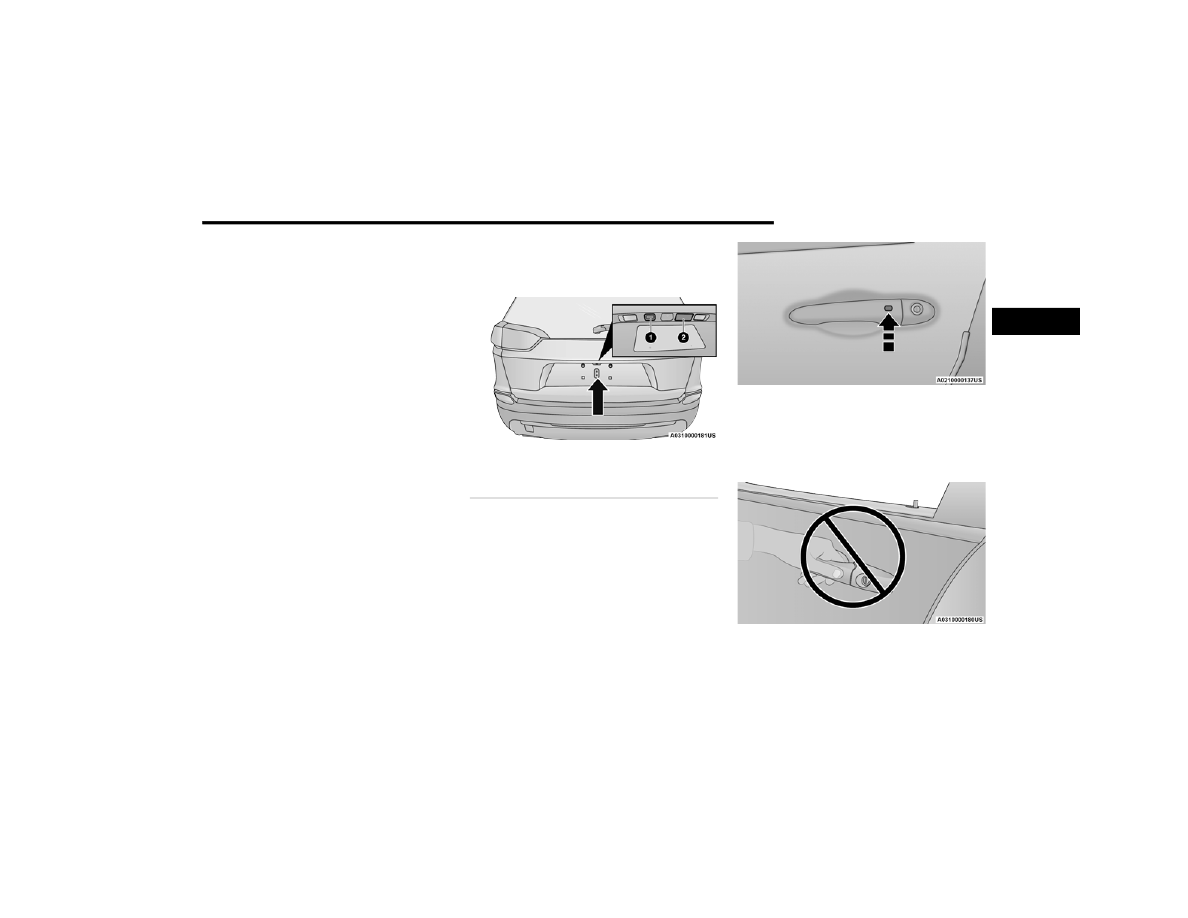
Liftgate Passive Entry / Release Handle Location

To Lock The Vehicle’s Doors And Liftgate
With one of the vehicle’s Passive Entry key fobs 

within 5 ft (1.5 m) of either front door handle, push 

the Passive Entry lock button located on the 

outside door handle.

Push The Door Handle Button To Lock

NOTE:

DO NOT grab the door handle when pushing the 

door handle lock button. This could unlock the 

door(s).

DO NOT Grab The Door Handle When Locking

1 — Passive Entry Button
2 — Liftgate Release Handle

2

26

GETTING TO KNOW YOUR VEHICLE


NOTE:

After pushing the door handle button, you must 

wait two seconds before you can lock or unlock 

the doors, using either Passive Entry door 

handle. This is done to allow you to check if the 

vehicle is locked by pulling the door handle 

without the vehicle unlocking.

If Passive Entry is disabled using the Uconnect 

Settings, the key protection described in 

"Frequency Operated Button Integrated Key 

(FOBIK-Safe)" remains active/functional.

The Passive Entry system will not operate if the 

key fob battery is depleted  

Ú

page 308.

A

UTOMATIC

 U

NLOCK

 D

OORS

 O

N

 E

XIT


The doors will unlock automatically on vehicles 

with power door locks if:
1. The Automatic Unlock Doors On Exit feature is 

enabled within Uconnect Settings  

Ú

page 150.

2. All doors are closed.
3. The gear selector was not in PARK, then is 

placed in PARK.

4. Any door is opened.

A

UTOMATIC

 D

OOR

 L

OCKS

 — 

I

F

 E

QUIPPED


The auto door lock feature default condition is 

enabled. When enabled, the door locks will lock 

automatically when the vehicle's speed exceeds 

15 mph (24 km/h). The auto door lock feature is 

enabled/disabled in the Uconnect Settings.

C

HILD

-P

ROTECTION

 D

OOR

 L

OCK


S

YSTEM

 — R

EAR

 D

OORS


To provide a safer environment for small children 

riding in the rear seats, the rear doors are 

equipped with a Child-Protection Door Lock 

system.
To use the system, open each rear door, use a flat 

blade screwdriver (or emergency key) and rotate 

the dial to the lock or unlock position. When the 

system on a door is engaged, that door can only be 

opened by using the outside door handle even if 

the inside door lock is in the unlocked position.

Child-Protection Door Lock Function

NOTE:

When the Child-Protection Door Lock system is 

engaged, the door can be opened only by using 

the outside door handle even though the inside 

door lock is in the unlocked position.

After engaging the Child-Protection Door Lock 

system, always test the door from the inside to 

make certain it is in the locked position.

For emergency exit with the system engaged, 

rotate the door lock button until the lock indi

-

cator is hidden (unlocked position), roll down 

the window, and open the door with the outside 

door handle.

GETTING TO KNOW YOUR VEHICLE

27

NOTE:

Always use this device when carrying children. 

After engaging the child lock on both rear doors, 

check for effective engagement by trying to open a 

door with the internal handle. Once the 

Child-Protection Door Lock system is engaged, it is 

impossible to open the doors from inside the 

vehicle. Before getting out of the vehicle, be sure to 

check that there is no one left inside.

STEERING WHEEL

T

ILT

/T

ELESCOPING

 S

TEERING

 C

OLUMN

This feature allows you to tilt the steering column 

upward or downward. It also allows you to lengthen 

or shorten the steering column. The tilt/

telescoping lever is located below the steering 

wheel at the end of the steering column.

Tilt/Telescoping Lever

To unlock the steering column, push the control 

handle downward (toward the floor). To tilt the 

steering column, move the steering wheel upward 

or downward as desired. To lengthen or shorten 

the steering column, pull the steering wheel 

outward or push it inward as desired. To lock the 

steering column in position, push the control 

handle upward until fully engaged.

H

EATED

 S

TEERING

 W

HEEL

 — 

I

F

 E

QUIPPED


The steering wheel contains a heating 

element that helps warm your hands in 

cold weather. The heated steering wheel 

has only one temperature setting. Once 

the heated steering wheel has been turned on, a 

sensor will monitor the temperature of the steering 

wheel and adjust the power level to maintain an 

optimum heat level.
The heated steering wheel control button is 

located within the Uconnect system. You can gain 

access to the control button through the climate 

screen or the controls screen.

Press the heated steering wheel button once to 

turn the heating element on.

Press the heated steering wheel button a 

second time to turn the heating element off.

NOTE:

The engine must be running for the heated 

steering wheel to operate.
For information on use with the Remote Start 

system, see  

Ú

page 21.

WARNING!

Avoid trapping anyone in a vehicle in a collision. 

Remember that the rear doors can only be 

opened from the outside when the Child-Protec

-

tion Door Lock system is engaged (locked).

WARNING!

Do not adjust the steering column while driving. 

Adjusting the steering column while driving or 

driving with the steering column unlocked, could 

cause the driver to lose control of the vehicle. 

Failure to follow this warning may result in 

serious injury or death.

2

28

GETTING TO KNOW YOUR VEHICLE


UCONNECT VOICE RECOGNITION  

I

NTRODUCING

 V

OICE

 R

ECOGNITION

Start using Uconnect Voice Recognition with these 

helpful quick tips. This section provides Voice 

Commands and tips you need to know to control 

your vehicle’s Voice Recognition (VR) system.

Uconnect 4C NAV With 8.4-inch Display

B

ASIC

 V

OICE

 C

OMMANDS

The basic Voice Commands below can be given at 

any point while using your Uconnect system.
Push the VR button  . After the beep, say:

“Cancel” to stop a current voice session.

“Help” to hear a list of suggested Voice 

Commands.

“Repeat” to listen to the system prompts again.

Notice the visual cues that inform you of your Voice 

Recognition system’s status.

G

ET

 S

TARTED

The   VR button is used to activate/deactivate 

your Voice Recognition system.

Helpful hints for using Voice Recognition:

Reduce background noise. Wind noise and 

passenger conversations are examples of noise 

that may impact recognition.

Speak clearly at a normal pace and volume 

while facing straight ahead.

Each time you give a Voice Command, first push 

the VR button, wait until after the beep, then say 

your Voice Command.

You can interrupt the help message or system 

prompts by pushing the VR button and saying a 

Voice Command from the current category.

Uconnect Voice Command Buttons

WARNING!

Persons who are unable to feel pain to the 

skin because of advanced age, chronic illness, 

diabetes, spinal cord injury, medication, 

alcohol use, exhaustion, or other physical 

conditions must exercise care when using the 

heated steering wheel. It may cause burns 

even at low temperatures, especially if used 

for long periods.

Do not place anything on the steering wheel 

that insulates against heat, such as a blanket 

or steering wheel covers of any type and mate

-

rial. This may cause the heated steering wheel 

to overheat.

1 — Push To Start Or Answer A Phone Call And 

Send Or Receive A Text
2 — Push The Voice Recognition Button To Begin 

Radio, Media, And Climate Functions

GETTING TO KNOW YOUR VEHICLE

29

A

DDITIONAL

 I

NFORMATION

Uconnect are registered trademarks and Mopar 

Owner Connect is a trademark of FCA US LLC. 

Android™ is a trademark of Google Inc. SiriusXM® 

and all related marks and logos are trademarks of 

SiriusXM® Radio Inc.  

Ú

page 308.

For Uconnect system support, call 

1-877-855-8400 (24 hours a day 7 days a week) 

or visit DriveUconnect.com (US) or 

DriveUconnect.ca (Canada).

DRIVER MEMORY SETTINGS — IF EQUIPPED 

This feature allows the driver to save up to two 

different memory profiles for easy recall through a 

memory switch. Each memory profile saves 

desired position settings for the following features:

Driver seat

Easy Entry/Exit seat (if equipped)

Side mirrors

A set of desired radio station presets

NOTE:

Your vehicle is equipped with two key fobs, each 

can be linked to either memory position 1 or 2.

Be sure to program the radio presets prior to 

programming the memory settings.

The memory settings switch is located on the 

driver’s door trim panel. The switch consists of 

three buttons:

The set (S) button, which is used to activate the 

memory save function.

The (1) and (2) buttons which are used to recall 

either of two saved memory profiles.

Driver Memory Switch

P

ROGRAMMING

 T

HE

 M

EMORY

 F

EATURE

To create a new memory profile, perform the 

following:

NOTE:

Saving a new memory profile will erase the 

selected profile from memory.
1. Place the vehicle’s ignition in the ON/RUN 

position.

2. Adjust all memory profile settings to desired 

preferences (i.e., seat, side mirror and radio 

station presets).

3. Push the set (S) button on the memory switch, 

and then push the desired memory button (1 

or 2) within five seconds. The instrument 

cluster display will display which memory 

position is being set.

NOTE:

Memory profiles can be set without the vehicle in 

PARK, but the vehicle must be in PARK to recall a 

memory profile.

L

INKING

 A

ND

 U

NLINKING

 T

HE

 K

EY

 F

OB


T

O

 M

EMORY

Your remote keyless entry key fob can be 

programmed to recall one of two saved memory 

profiles.

NOTE:

Before programming your key fob you must select 

the “Personal Settings Linked to Key Fob” feature 

through the Uconnect system  

Ú

page 150.

To program your key fob, perform the following:
1. Place the vehicle’s ignition in the OFF 

position.

2. Select the desired memory profile 1 or 2.

2

30

GETTING TO KNOW YOUR VEHICLE


(Continued)

3. Push and release the set (S) button on the 

memory switch, then within five seconds push 

and release the button (1) or (2) accordingly. 

“Memory Profile Set” (1 or 2) will display in the 

instrument cluster display.

4. Push and release the lock button on the key 

fob within 10 seconds.

NOTE:

Your key fob can be unlinked from your memory 

settings by pushing the set (S) button, followed by 

pushing the unlock button on the key fob within 10 

seconds.

M

EMORY

 P

OSITION

 R

ECALL

NOTE:

If a recall is attempted when the vehicle is not in 

PARK, a message will display in the instrument 

cluster display.
To recall the memory settings for driver one or two, 

push the desired memory button number (1 or 2) 

or the unlock button on the key fob linked to the 

desired memory position.
A recall can be canceled by pushing any of the 

memory buttons (S, 1, or 2) during a recall. When 

a recall is canceled, the driver seat will stop 

moving. A delay of one second will occur before 

another recall can be selected.

SEATS    

Seats are a part of the Occupant Restraint system 

of the vehicle.

M

ANUAL

 A

DJUSTMENT

 (F

RONT


S

EATS

) — I

F

 E

QUIPPED

Some models may be equipped with front driver 

and passenger side manual seats. The forward/

rearward adjustment bar is located at the front of 

the seat, near the floor. Height and recline levers 

are located on the outboard side of the seat.

Manual Seat Adjustments

NOTE:

Do not place objects beneath the adjustable seat 

or impede proper seat adjustment.

WARNING!

It is dangerous to ride in a cargo area, inside 

or outside of a vehicle. In a collision, people 

riding in these areas are more likely to be seri

-

ously injured or killed.

Do not allow people to ride in any area of your 

vehicle that is not equipped with seats and 

seat belts. In a collision, people riding in these 

areas are more likely to be seriously injured or 

killed.

Be sure everyone in your vehicle is in a seat 

and using a seat belt properly.

1 — Forward/Rearward Adjustment Bar
2 — Height Adjustment Lever
3 — Recline Lever

WARNING!

Adjusting a seat while the vehicle is moving is 

dangerous. The sudden movement of the seat 

could cause you to lose control. The seat belt 

might not be adjusted properly and you could 

be injured. Adjust the seat only while the 

vehicle is parked.

GETTING TO KNOW YOUR VEHICLE

31

(Continued)

Manual Front Seat Forward/Rearward 

Adjustment

On models equipped with manual seats, the 

adjustment bar is located at the front of the seats, 

near the floor.
While sitting in the seat, lift up on the bar and move 

the seat forward or rearward. Release the bar once 

you have reached the desired position. Then, using 

body pressure, move forward and rearward on the 

seat to be sure that the seat adjusters have 

latched.

Manual Seat Height Adjustment

The driver’s and passenger’s seat height can be 

raised or lowered by using a lever, located on the 

outboard side of the seat. Pull upward on the lever 

to raise the seat height or push downward on the 

lever to lower the seat height.

Manual Front Seat Recline Adjustment

To adjust the seatback, lift the lever located on the 

outboard side of the seat, lean back to the desired 

position and release the lever. To return the 

seatback, lift the lever, lean forward and release 

the lever.

M

ANUAL

 A

DJUSTMENT

 (R

EAR

 S

EATS

)

Rear Seat Forward/Rearward 

Adjustment — If Equipped

Lift up on the adjusting bar located at the front of 

the seat near the floor and release it when the seat 

is at the desired position. Then, using body 

pressure, move forward and rearward on the seat 

to be sure that the seat adjusters have latched.

Rear Seat Adjustment Bar

Do not ride with the seatback reclined so that 

the shoulder belt is no longer resting against 

your chest. In a collision you could slide under 

the seat belt and be seriously or even fatally 

injured. Use the recliner only when the vehicle 

is parked.

WARNING!

Adjusting a seat while driving may be 

dangerous. Moving a seat while driving could 

result in loss of control which could cause a 

collision and serious injury or death.

WARNING!

Seats should be adjusted before fastening the 

seat belts and while the vehicle is parked. 

Serious injury or death could result from a 

poorly adjusted seat belt.

WARNING!

Do not ride with the seatback reclined so that 

the shoulder belt is no longer resting against 

your chest. In a collision you could slide under 

the seat belt, which could result in serious injury 

or death.

WARNING!

WARNING!

Do not pile luggage or cargo higher than the top 

of the seatback. This could impair visibility or 

become a dangerous projectile in a sudden stop 

or collision.

2

32

GETTING TO KNOW YOUR VEHICLE


Rear Seat Recline Adjustment

The rear seatback also reclines for additional 

passenger comfort. On vehicles equipped with a 

sliding rear seat, pull on the pull strap while sitting 

in the rear seat to recline the seatback.

Rear Sliding Seat Recliner Pull Straps

On vehicles equipped with a fixed rear seat, pull on 

the handle located on the upper outboard side of 

the seatback.

Rear Fixed Seat Recline Lever

60/40 Split Folding Rear Seat With 

Fold-Flat Feature 

To provide additional storage area, each rear seat 

can be folded flat. This allows for extended cargo 

space and still maintains some rear seating room.

NOTE:

Prior to folding the rear seat, it may be necessary 

to position the front seat to its mid-track position. 

Also, be sure that the front seats are fully upright 

and positioned forward. This will allow the rear seat 

to fold down easily.

WARNING!

Do not ride with the seatback reclined so that 

the shoulder belt is no longer resting against 

your chest. In a collision you could slide under 

the seat belt, which could result in serious injury 

or death.

WARNING!

It is extremely dangerous to ride in a cargo 

area, inside or outside of a vehicle. In a colli

-

sion, people riding in these areas are more 

likely to be seriously injured or killed.

Do not allow people to ride in any area of your 

vehicle that is not equipped with seats and 

seat belts.

Be sure everyone in your vehicle is in a seat 

and using a seat belt properly.

GETTING TO KNOW YOUR VEHICLE

33

TO LOWER THE REAR SEAT

1. Lift the seatback release lever located on the 

upper outer edge of the seat. If your vehicle is 

equipped with a sliding rear seat, you can also 

pull the pull strap located on the middle outer 

edge of the seat.

Rear Sliding Seat Release Lever And Pull Strap

Rear Fixed Seat Release Lever

2. Fold the rear seatback completely forward.

NOTE:

You may experience deformation in the seat 

cushion from the seat belt buckles if the seats are 

left folded for an extended period of time. This is 

normal and by simply placing the seats to the open 

position, over time the seat cushion will return to 

its normal shape.

TO RAISE THE REAR SEAT

NOTE:

If interference from the cargo area prevents the 

seatback from fully locking, you will have difficulty 

returning the seat to its proper position.
Raise the seatback and lock it into place.

P

OWER

 A

DJUSTMENT

 (F

RONT

 S

EATS

) — 

I

F

 E

QUIPPED

Some models may be equipped with a power 

driver's seat and/or power passenger seat. The 

power seat switches are located on the outboard 

side of the seat near the floor, and control the 

movement of the seat cushion and seatback.

Power Seat Switches

NOTE:

Do not place objects beneath the adjustable seat 

or impede proper seat adjustment.

WARNING!

Be certain that the seatback is securely locked 

into position. If the seatback is not securely 

locked into position the seat will not provide the 

proper stability for child seats and/or 

passengers. An improperly latched seat could 

cause serious injury.

1 — Seat Switch
2 — Seatback Switch

2

34

GETTING TO KNOW YOUR VEHICLE


Adjusting The Seat Forward Or Rearward

The seat can be adjusted both forward and 

rearward by pushing the seat switch in the desired 

direction. Release the switch when the desired 

position has been reached.

Adjusting The Seat Up Or Down 

The height of the seats can be adjusted up or 

down. Pull upward or push downward on the seat 

switch, the seat will move in the direction of the 

switch. Release the switch when the desired 

position is reached.

Tilting The Seat Up Or Down

The angle of the seat cushion can be adjusted in 

two directions. Pull upward or push downward on 

the front of the seat switch, the front of the seat 

cushion will move in the direction of the switch. 

Release the switch when the desired position has 

been reached.

Reclining The Seatback Forward Or 

Rearward

The seatback can be reclined both forward and 

rearward by using the seatback recline switch. The 

seatback will move in the direction of the switch. 

Release the switch when the desired position has 

been reached.

Power Lumbar — If Equipped

Vehicles equipped with power driver or passenger 

seats may be equipped with power lumbar. The 

power lumbar switch is located on the outboard 

side of the power seat. Push the switch forward or 

rearward to increase or decrease the lumbar 

support.

Power Lumbar Switch

Easy Entry/Exit Seat — If Equipped 

This feature provides automatic driver seat 

positioning to enhance driver mobility when 

entering and exiting the vehicle.
The distance the driver seat moves depends on 

where you have the driver seat positioned when 

you place the vehicle’s ignition in the OFF position.

When you place the vehicle’s ignition in the OFF 

position, the driver seat will move about 

2.4 inches (60 mm) rearward if the driver seat 

position is greater than or equal to 2.7 inches 

(67.7 mm) forward of the rear stop. The seat will 

return to its previously set position when you 

place the vehicle’s ignition in the ACC or RUN 

position.

The Easy Entry/Exit feature is not available 

when the driver seat position is less than 

0.9 inches (22.7 mm) forward of the rear stop. 

At this position, there is no benefit to the driver 

by moving the seat for Easy Exit or Easy Entry.

When enabled in Uconnect Settings, Easy Entry 

and Easy Exit positions are stored in each memory 

setting profile  

Ú

page 29.

NOTE:

The Easy Entry/Exit feature is enabled or disabled 

through the programmable features in the 

Uconnect system  

Ú

page 150.

WARNING!

Do not ride with the seatback reclined so that 

the shoulder belt is no longer resting against 

your chest. In a collision you could slide under 

the seat belt, which could result in serious injury 

or death.

GETTING TO KNOW YOUR VEHICLE

35

H

EATED

 S

EATS

 — I

F

 E

QUIPPED


Front Heated Seats — If Equipped 

The front heated seats control buttons 

are located within the Uconnect system. 

You can gain access to the control 

buttons through the climate screen and 

the controls screen.
You can choose from HI, LO, or OFF heat settings. 

The indicator arrows in the touchscreen buttons 

indicate the level of heat in use. Two indicator 

arrows will illuminate for HI, and one for LO. 

Turning the heating elements off will return the 

user to the radio screen.

Press the heated seat button once to turn the HI 

setting on.

Press the heated seat button a second time to 

turn the LO setting on.

Press the heated seat button a third time to turn 

the heating elements off.

NOTE:

Once a heat setting is selected, heat will be felt 

within two to five minutes.

The engine must be running for the heated 

seats to operate.

The level of heat selected will stay on until the 

operator changes it.

For information on use with the Remote Start 

system, see  

Ú

page 21.

Rear Heated Seats — If Equipped

On some models, the two outboard rear 

seats are equipped with heated seats. The 

heated seat switches for these seats are 

located on the rear of the center console.

There are two heated seat switches that allow the 

rear passengers to operate the seats 

independently. Indicator lights in each switch 

indicate the level of heat in use. Two indicator 

lights will illuminate for HI, one for LO and none for 

off.

Push the heated seat button once to turn the HI 

setting on.

Push the heated seat button a second time to 

turn the LO setting on.

Push the heated seat button a third time to turn 

the heating elements off.

NOTE:

The level of heat selected will stay on until the 

operator changes it.

V

ENTILATED

 S

EATS

 — I

F

 E

QUIPPED

Located in the seat cushion and seatback are fans 

that draw the air from the passenger compartment 

and move air through fine perforations in the seat 

cover to help keep the occupant cooler in higher 

ambient temperatures.

Front Ventilated Seats — If Equipped

The front ventilated seat controls are 

located within the climate and control 

screen in the Uconnect system. The fans 

operate at two speeds, HI and LO.

Press the ventilated seat button once to choose 

HI.

Press the ventilated seat button a second time 

to choose LO.

Press the ventilated seat button a third time to 

turn the ventilated seat off.

WARNING!

Persons who are unable to feel pain to the 

skin because of advanced age, chronic illness, 

diabetes, spinal cord injury, medication, 

alcohol use, exhaustion or other physical 

condition must exercise care when using the 

seat heater. It may cause burns even at low 

temperatures, especially if used for long 

periods of time.

Do not place anything on the seat or seatback 

that insulates against heat, such as a blanket 

or cushion. This may cause the seat heater to 

overheat. Sitting in a seat that has been over

-

heated could cause serious burns due to the 

increased surface temperature of the seat.

2

36

GETTING TO KNOW YOUR VEHICLE


(Continued)

NOTE:

The engine must be running for the ventilated 

seats to operate.
For information on use with the Remote Start 

system, see  

Ú

page 21.

H

EAD

 R

ESTRAINTS


Head restraints are designed to reduce the risk of 

injury by restricting head movement in the event of 

a rear impact. Head restraints should be adjusted 

so that the top of the head restraint is located 

above the top of your ear.

NOTE:

Do not reverse the head restraints (making the rear 

of the head restraint face forward) in an attempt to 

gain additional clearance to the back of your head.

Reactive Head Restraints — Front Seats

The front driver and passenger seats are equipped 

with Reactive Head Restraints (RHR). In the event 

of a rear impact, the RHRs will automatically 

extend forward minimizing the gap between the 

back of the occupant’s head and the RHR.
The RHRs will automatically return to their normal 

position following a rear impact. If the RHRs do not 

return to their normal position, see an authorized 

dealer immediately.
To raise the head restraint, pull upward on the 

head restraint. To lower the head restraint, push 

the adjustment button, located at the base of the 

head restraint, and push downward on the head 

restraint.

NOTE:

To remove the head restraint, raise it as far as it 

can go. Then, push the release button and the 

adjustment button at the base of each post while 

pulling the head restraint up. Seatback angle may 

need to be adjusted to fully remove the head 

restraint. To reinstall the head restraint, put the 

head restraint posts into the holes and push 

downward. Then adjust the head restraint to the 

appropriate height.

Front Head Restraint

WARNING!

All occupants, including the driver, should not 

operate a vehicle or sit in a vehicle’s seat until 

the head restraints are placed in their proper 

positions in order to minimize the risk of neck 

injury in the event of a crash.

Head restraints should never be adjusted 

while the vehicle is in motion. Driving a vehicle 

with the head restraints improperly adjusted 

or removed could cause serious injury or 

death in the event of a collision.

1 — Release Button
2 — Adjustment Button

WARNING!

A loose head restraint thrown forward in a 

collision or hard stop could cause serious 

injury or death to occupants of the vehicle. 

Always securely stow removed head restraints 

in a location outside the occupant compart

-

ment.

ALL the head restraints MUST be reinstalled in 

the vehicle to properly protect the occupants. 

Follow the reinstallation instructions above 

prior to operating the vehicle or occupying a 

seat.

GETTING TO KNOW YOUR VEHICLE

37

Rear Head Restraints

The rear outboard head restraints have two 

positions: up and down. The center head restraint 

has three positions: up, mid, and down. When the 

center seat is being occupied the head restraint 

should be adjusted to the occupant. When there is 

no occupant in the center seat, the head restraint 

can be lowered for maximum visibility for the 

driver.
To raise the head restraint, pull upward on the 

head restraint. To lower the head restraint, push 

the adjustment button, located at the base of the 

head restraint, and push downward on the head 

restraint.

NOTE:

To remove the head restraint, raise it as far as it 

can go. Then, push the release button and the 

adjustment button at the base of each post 

while pulling the head restraint up. To reinstall 

the head restraint, put the head restraint posts 

into the holes and push downward. Then, adjust 

the head restraint to the appropriate height.

The seatback may need to be reclined in order 

to fully remove the outboard head restraints.

Outboard Head Restraint

Center Head Restraint

Do not place items over the top of the Reac

-

tive Head Restraint, such as coats, seat 

covers or portable DVD players. These items 

may interfere with the operation of the Reac

-

tive Head Restraint in the event of a collision 

and could result in serious injury or death.

WARNING!

1 — Release Button
2 — Adjustment Button

1 — Adjustment Button
2 — Release Button

WARNING!

ALL the head restraints MUST be reinstalled in 

the vehicle to properly protect the occupants. 

Follow the reinstallation instructions above prior 

to operating the vehicle or occupying a seat.

2

38

GETTING TO KNOW YOUR VEHICLE


MIRRORS 

I

NSIDE

 R

EARVIEW

 M

IRROR

Manual Mirror — If Equipped

The mirror head can be adjusted up, down, left, 

and right. The mirror should be adjusted to center 

on the view through the rear window.
Headlight glare from vehicles behind you can be 

reduced by moving the small control under the 

mirror to the night position (toward the rear of the 

vehicle). The mirror should be adjusted while set in 

the day position (toward the windshield).

Adjusting Rearview Mirror

NOTE:

The vehicle is equipped with either a single ball 

joint mirror or a two ball adjustable prism mirror. 

The single ball joint is a twist-on mirror that has 

a fixed position at the windshield. The mirror 

installs on the windshield button with a counter

-

clockwise rotation and requires no tools for 

mounting.

The two ball joint is mounted to a tombstone 

button on the windshield with a set screw. Tools 

are required for mounting and dismounting.

Auto Dimming Mirror — If Equipped 

A single ball joint mirror is provided in the vehicle. 

It is a twist on mirror that has a fixed position at the 

windshield. The mirror installs on the windshield 

button with a counterclockwise rotation and 

requires no tools for mounting. The rearview mirror 

can be adjusted up, down, left, and right. The 

mirror should be adjusted to center on the view 

through the rear window.

Automatic Dimming Button

NOTE:

The automatic dimming feature is disabled when 

the vehicle is in REVERSE to improve rear view 

viewing.

The automatic dimming feature can be turned on 

or off through the touchscreen, or using the power 

button on the base of the mirror.

Press the mirror dimmer button once to turn the 

feature on.

Press the mirror dimmer button a second time 

to turn the feature off.

NOTE:

In some cases, there may not be a button. If there 

is no power button, the mirror will be in default 

auto dimming mode.

I

LLUMINATED

 V

ANITY

 M

IRRORS

An illuminated vanity mirror is on each sun visor. To 

use the mirror, rotate the sun visor down and swing 

the mirror cover upward. The lights will turn on 

automatically. Closing the mirror cover will turn off 

the light.

CAUTION!

To avoid damage to the mirror during cleaning, 

never spray any cleaning solution directly onto 

the mirror. Apply the solution onto a clean cloth 

and wipe the mirror clean.

GETTING TO KNOW YOUR VEHICLE

39

Sun Visor “Slide-On-Rod” Feature

The sun visor “Slide-On-Rod” feature allows for 

additional flexibility in positioning the sun visor to 

block out the sun.
1. Fold down the sun visor.
2. Unclip the visor from the corner clip.
3. Pull the sun visor toward the inside rearview 

mirror to extend it.

O

UTSIDE

 M

IRRORS


To receive maximum benefit, adjust the outside 

mirror(s) to center on the adjacent lane of traffic 

with a slight overlap of the view obtained on the 

inside mirror.

NOTE:

The passenger side convex outside mirror will give 

a much wider view to the rear, and especially of the 

lane next to your vehicle.

P

OWER

 M

IRRORS

The power mirror control switch is located on the 

driver's side door trim panel.
The power mirror controls consist of mirror select 

buttons and a four-way mirror control switch. To 

adjust a mirror, push the mirror select button for 

the mirror that you want to adjust. Using the mirror 

control switch, push on any of the four arrows for 

the direction that you want the mirror to move.

Power Mirror Switches

Power mirror position can be saved as part of the 

Driver Memory Settings (if equipped)  

Ú

page 29.

H

EATED

 M

IRRORS

 — I

F

 E

QUIPPED


These mirrors are heated to melt frost or 

ice. This feature will be activated 

whenever you turn on the rear window 

defroster (if equipped)  

Ú

page 51.

UNIVERSAL GARAGE DOOR OPENER 

(HOMELINK®) — IF EQUIPPED   

HomeLink® Buttons On Sun Visor

Use this QR code to access your 

digital experience.

HomeLink® replaces up to 

three hand-held transmitters 

that operate devices such as 

garage door openers, motor

-

ized gates, lighting, or home 

WARNING!

Vehicles and other objects seen in an outside 

convex mirror will look smaller and farther away 

than they really are. Relying too much on side 

convex mirrors could cause you to collide with 

another vehicle or other object. Use your inside 

mirror when judging the size or distance of a 

vehicle seen in a side convex mirror.

1 — Left Mirror Selection
2 — Right Mirror Selection
3 — Mirror Direction Control

2

40

GETTING TO KNOW YOUR VEHICLE


security systems. The HomeLink® unit is 

powered by your vehicle’s 12 Volt battery.

The HomeLink® buttons that are located in the 

overhead console or sunvisor designate the 

three different HomeLink® channels.

To operate HomeLink®, push and release any 

of the programmed HomeLink® buttons. These 

buttons will activate the devices they are 

programmed to with each press of the corre

-

sponding HomeLink® button.

The HomeLink® indicator light is located above 

the center button.

NOTE:

HomeLink® is disabled when the Vehicle Security 

system is active  

Ú

page 308.

B

EFORE

 Y

OU

 B

EGIN

 P

ROGRAMMING


H

OME

L

INK

®

For efficient programming and accurate 

transmission of the Radio Frequency (RF) signal, it 

is recommended that a new battery be placed in 

the hand-held transmitter of the device that is 

being programmed to the HomeLink® system. 

Make sure your hand-held transmitter is 

programmed to activate the device you are trying 

to program your HomeLink® button to.
Ensure that your vehicle is parked outside of the 

garage before you begin programming.

It is recommended that you erase all the channels 

of your HomeLink® before you use it for the first 

time.

E

RASING

 A

LL

 T

HE

 H

OME

L

INK

® 

C

HANNELS

To erase the channels, follow this procedure:
1. Place the ignition switch into the ON/RUN 

position.

2. Push and hold the two outside HomeLink® 

buttons (I and III) for up to 20 seconds, or until 

the HomeLink® indicator light flashes.

NOTE:

Erasing all channels should only be performed 

when programming HomeLink® for the first time. 

Do not erase channels when programming addi

-

tional buttons.

I

DENTIFYING

 W

HETHER

 Y

OU

 H

AVE

 A 

R

OLLING

 C

ODE

 O

R

 N

ON

-R

OLLING

 C

ODE


D

EVICE

Before programming a device to one of your 

HomeLink® buttons, you must determine whether 

the device has a rolling code or non-rolling code.

Rolling Code Devices
To determine if your device has a rolling code, a 

good indicator is its manufacturing date. Typically, 

devices manufactured after 1995 have rolling 

codes. A device with a rolling code will also have a 

“LEARN” or “TRAIN” button located where the 

antenna is attached to the device. The button may 

not be immediately visible when looking at the 

device. The name and color of the button may vary 

slightly by manufacturer.

NOTE:

The “LEARN” or “TRAIN” button is not the button 

you normally use to operate the device.
Non-rolling Code Devices
Most devices manufactured before 1995 will not 

have a rolling code. These devices will also not 

have a “LEARN” or “TRAIN” button.

P

ROGRAMMING

 H

OME

L

INK

® T

O

 A 

G

ARAGE

 D

OOR

 O

PENER

To program any of the HomeLink® buttons to 

activate your garage door opener motor, follow the 

steps below:

NOTE:

All HomeLink® buttons are programmed using this 

procedure. You do not need to erase all channels 

when programming additional buttons.


Content      ..      1      2      3      ..