Jaguar XJ (X350). Manual - part 767
Circuit
Pin
Cylinder 1 output Pin 01
Cylinder 2 output Pin 02
Cylinder 3 output Pin 03
Cylinder 4 output Pin 04
Cylinder 5 output Pin 05
Cylinder 6 output Pin 06
3.
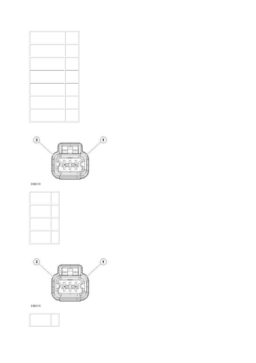
Circuit
Pin
Cylinder 1 01
Cylinder 2 02
Cylinder 3 03
4.
Circuit
Pin