Iveco EuroCargo (12 to 26 t). Manual - part 92
84530
84531
84532
84533
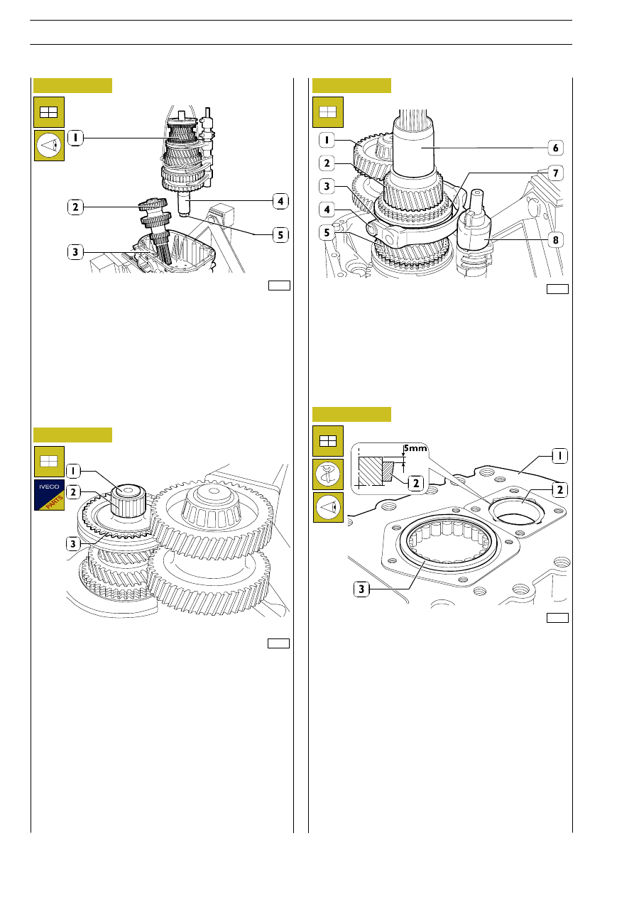
Figure 83
Figure 84
Figure 85
Figure 86
Place countershaft (2) in rear half case (3). Lift the unit (1) thus
assembled. Apply tool SP. 2413 (4) to the output shaft end,
secure it by means of nut (5) and insert it into the rear half case.
While performing this operation, verify that the output shaft
is inserted into the support bearing, the internal driving shaft
is inserted into its respective bushing, and that the
countershaft can be matched with the output shaft.
Mount synchronizing ring (3) and roller bearing (2) on output
shaft (1).
Mount motion inlet shaft (2) by slightly lifting output shaft (5)
and opening out countershaft (1).
Remove the rope.
Place fork (4) pads (3) on sliding sleeve (7), then connect fork
(4) to selector (8) pin.
Force-fit tool SP. 2413 (6) onto motion inlet shaft (2).
Use beater 99374092 and handle 99370007 to mount the
countershaft tapered-roller bearing outer race (2) into front
half case (1), so that it is slightly embedded compared to half
case (1) outer plane by ~ 5 mm.
Mount cylindrical roller bearing (3) for the motion inlet shaft.
GEARBOX EATON FSO 5206B
E
URO
C
ARGO
T
ECTOR
12-26 t
218
Base - February 2003