Iveco Daily. Manual - part 271


  Index      Iveco     Iveco Daily - service repair manual 2004 year


Search            


Content   ..  269  270  271  272   ..


Iveco Daily. Manual - part 271


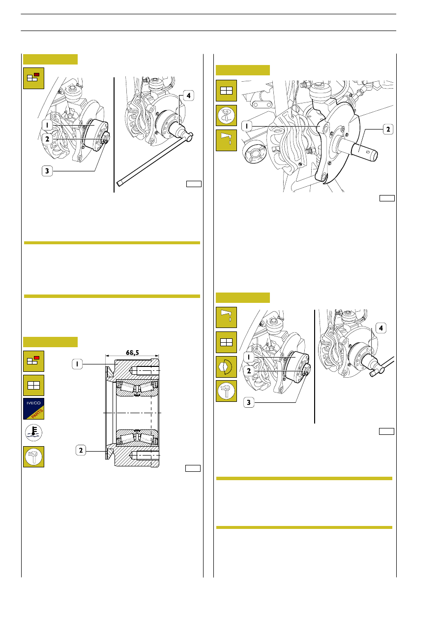
The possible extraction of the phonic wheel (2) from the
wheel hub (1) is made using normal tools.

The phonic wheel must be heated up to a temperature of
150

°C before the assembly on the wheel hub.

When the assembly is ended, make sure that the “phonic”
wheel perfectly rests on the hub housing and that is
positioned at the dimension shown in figure.

Check that the orthogonality and oscillation of the phonic (2)
wheel is no greater than 0.1 mm.

Figure 10

Figure 11

Loosen the screw (3).

With the socket wrench (4), remove the nut (2) securing the
wheel hub (1) to the pin of the stub axle.

Extract the wheel hub (1) from the pin of the stub axle.

526712

Replacing phonic wheel

62916

62917

When the wheel hub has been keyed (1), position the
washer, screw the nut (2) and using the socket wrench (4)
tighten the nut (2) to the prescribed torque.
Tighten the check screw (3) of the nut to the prescribed
torque.

Screw tool 99370496 (2) on kingpin (1), grease tool external
surface (2) with Tutela MR3.

62918

62919

Figure 12

Figure 13

Re-fitting

Refit the wheel hub (1).

If any trouble is found with the wheel hub or
bearing, the assembly needs to be replaced since
the parts are not supplied as single spares.

When repairing the wheel hub (1), take care not
to damage the phonic wheel (3).

NOTE

The wheel hub must be keyed without forcing.. If
there are difficulties, do not assemble since the
bearing may be damaged.
Extract the wheel hub, check the cause of the
difficulties and eliminate them.

NOTE

46

AXLE 5823

D

AILY

Base - May 2004

Refit cover (1).
Stop wheel hub rotation using the proper lever (3) and
tighten the fastening screws (1) to the specified torque.

Figure 14

62915

Fit brake disc (1) on wheel hub (2).

Figure 15

62921

Fit flange (1) on wheel hub. Stop wheel hub rotation using
the proper lever (3) and tighten the fastening screws (2) to
the specified torque.

Use the gauge with magnetic base to check brake disc
mismatching: it must be lower than 0.125 mm.

Wheel stud replacement

Replace wheel studs if found damaged by removing them
from the wheel hub.

Smear new stud threads with Loctite 270 and tighten to the
specified torque.

Once refitting is over, check stud squareness, max. error is

0.2 mm.

Figure 16

52268

Figure 17

62912

Rest brake calliper (2) and brake linings on stub axle (1).

Tighten brake calliper (2) fastening screws (1) to the specified
torque.

Fit the wheel on the flange and tighten the fastening screws
to the specified torque according to the sequence shown in
the figure.
Refit wheel rim cap.

Figure 18

89007

The brake lining with the wear sensor shall be fitted
on brake calliper piston side.

Comply with BRAKE section requirements to
move back the brake calliper piston using tool
99372236.

NOTE

AXLE 5823

47

D

AILY

48

AXLE 5823

D

AILY

Base - May 2004

WHEEL GEOMETRY

49

D

AILY

Wheel geometry

Page

DESCRIPTION

51

. . . . . . . . . . . . . . . . . . . . . . . . . .

WHEEL GEOMETRY

53

. . . . . . . . . . . . . . . . . . . . .

SPECIFICATIONS AND DATA

53

. . . . . . . . . . . . .

TIGHTENING TORQUES

53

. . . . . . . . . . . . . . . . .

TOOLS

54

. . . . . . . . . . . . . . . . . . . . . . . . . . . . . . . .

CHECKING CHARACTERISTIC ANGLES

55

. . . . .

-

Positioning jaws and projectors

55

. . . . . . . . . . . .

-

Electronic balancing of rim eccentricity

56

. . . . . .

-

Wheel alignment

56

. . . . . . . . . . . . . . . . . . . . . . .

-

Checking toe-in

57

. . . . . . . . . . . . . . . . . . . . . . . .

-

Front wheel deviation test
(vehicle wheelbase check)

57

. . . . . . . . . . . . . . . .

-

Checking camber

58

. . . . . . . . . . . . . . . . . . . . . . .

-

Checking king-pin angle and caster angle

58

. . . . .

-

Checking steering angles

59

. . . . . . . . . . . . . . . . .

-

Checking rear axle alignment

59

. . . . . . . . . . . . . .

-

Calculating thickness of spacers to be fitted
between tie rod mountings and
chassis side members (with the exception of
vehicles equipped with 5-mm thick chassis or
with transverse leaf-spring suspension)

60

. . . . . .


Content   ..  269  270  271  272   ..