Iveco Daily. Manual - part 259


  Index      Iveco     Iveco Daily - service repair manual 2004 year


Search            


Content   ..  257  258  259  260   ..


Iveco Daily. Manual - part 259


Position the dial gauge 99395684 (1) with a magnetic base
and measure the clearance between the pinion and crown
wheel on four opposite teeth of the crown wheel (2).

The average of the measurements must equal the required
value.

If a different clearance is found, remove the caps (3) again and
swap over the assembly position of the adjustment rings (2
and 4, Figure 61).

If this is not sufficient, replace the adjustment rings with ones
of a different thickness, but the total thickness must still be
the same as that of the adjustment rings removed.

This is so as not to change the total rolling torque.

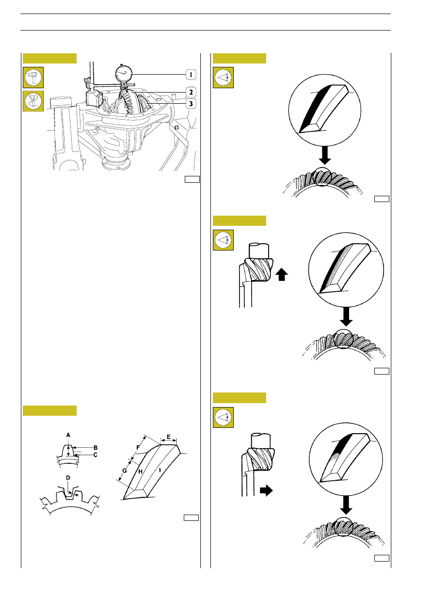
Apply a thin layer of Prussian blue on ring gear teeth by brush.

Turn the pinion and measure the impression of the contact
of the pinion toothing on the crown wheel toothing.

Here we illustrate the possible contacts with the corrections
to obtain precise coupling of the crown wheel and pinion.

51850

44603

Figure 64

Figure 65

A = Coupling depth
B = Crest
C = Side
D = Play

E = Greater base
F = Heel
G = Top land
H = Contact surface
I = Lateral surface

Figure 66

Figure 67

44604

Correct contact

44605

Excessive contact on tooth
bottom or flank.
Move away pinion and put
ring gear to pinion to adjust
clearance.

Figure 68

Excessive contact on heel
of tooth.
Move the ring bevel gear
towards the pinion and
then move the pinion away
from the ring bevel gear to
adjust clearance.

44606

116

REAR AXLES 450310

D

AILY

Revi - February 2005

Excessive contact on the
top land of the tooth.
Move the ring bevel gear
away from the pinion them
move the pinion towards
the ring bevel gear to adjust
clearance.

44608

Figure 69

Figure 70

44607

Excessive contact in the
upper part or crest of the
tooth.
Move the pinion towards
the ring bevel gear and then
move the ring bevel gear
away from the pinion to
adjust clearance.

51852

51846

Lubricate the internal lip of the seal (1).

With the key 99374456 (2) and grip 99370006 (3), mount
the seal in the axle housing.

Mount the coupling (1) and with the tool 99370317 (2) block
its rotation with the torque wrench (3).

Tighten the bevel pinion retaining nut to the required torque.

After having determined the prescribed coupling clearance,
tool 99370317 (2) prevents the flange (1) from rotating.

Unscrew the retaining nut and extract the flange (1) from the
bevel pinion.

51851

Figure 71

Figure 72

Figure 73

51853

Figure 74

Deform the collar of the nut (1) as shown in the figure at the
milling of the bevel pinion (2).

*

DIRECTION OF
ROTATION OF
THE NUT

REAR AXLES 450310

117

D

AILY

Revi - February 2005

Thoroughly clean the flange of the axle housing.

Apply LOCTITE 5910 sealant on the flange of the axle
housing to form a bead of approx. 5 mm diameter.

It must be uniform (no lumps), without any air bubbles, thin
areas or gaps.

Any flaws must be corrected in as short a time as possible.

Avoid using too much material to seal the joint.

Too much sealant would tend to come out on both sides of
the joint.

After applying the sealant, the joints need to be assembled
immediately (10 - 20 minutes).

To seal at a later date, there is product 21623 capable of
softening or liquefying the above-mentioned sealant.

It is essential to clean the surface to be sealed in order to
achieve good future sealing.

51854

51855

Figure 75

Figure 76

Mount the cover (1) and screw on the screws (2).

- Flanged screws (for solution without gasket).

- Screws with washer (for solution with gasket).

62098

Figure 77

Following the order shown in the figure, tighten the screws
to the torque of:

- flanged screws (for solution without gasket) 80

÷ 95 Nm;

- screws with washer (for solution with gasket) 31.5

÷

38.5 Nm.

Complete assembly taking the following precautions:

Mount the drive shafts as described under the heading:
”525030 overhauling hubs”.

Apply LOCTITE 577 thread-locking oil on the oil drain plug
thread, screw it into the axle housing, tightening it to the
required torque.

Add lubricating oil in the required quantity and grade through
the hole.

Apply LOCTITE 577 thread-locking oil on the inspection
plug thread, screw it into the axle housing, tightening it to the
required torque.

Take the assembly off the stand.

α

The assembly should be put back on its mounting
to prevent the dust guards and/or brake discs from
getting damaged.

NOTE

118

REAR AXLES 450310

D

AILY

Revi - February 2005

AXLES

1

D

AILY

SECTION 7

5206

Axles

Page

This section contains:

DIAGNOSTICS

3

. . . . . . . . . . . . . . . . . . . . . . . . .

AXLE 5817

7

. . . . . . . . . . . . . . . . . . . . . . . . . . . . .

AXLE 5818

21

. . . . . . . . . . . . . . . . . . . . . . . . . . . . .

AXLE 5819

29

. . . . . . . . . . . . . . . . . . . . . . . . . . . . .

AXLE 5823

37

. . . . . . . . . . . . . . . . . . . . . . . . . . . . .

WHEEL GEOMETRY

49

. . . . . . . . . . . . . . . . . . . . .


Content   ..  257  258  259  260   ..