Iveco Daily. Manual - part 258


  Index      Iveco     Iveco Daily - service repair manual 2004 year


Search            


Content   ..  256  257  258  259   ..


Iveco Daily. Manual - part 258


On a surface plate (2), zero a dial gauge (1) set on the
mounting 99395728 (3) and pre-load it slightly.

51837

18241

51838

51839

Figure 47

Figure 48

Figure 49

Figure 50

Figure 51

Using the punch 99374091 (3) and grip 99370006 (4), mount
the external ring (2) of the tapered roller bearing in the axle
housing (1).

Set adjusting ring (4), removed at disassembling, into rear
axle casing (5).
Using the punch 99374092 (2) and grip 99370007 (1), mount
the external ring (3) of the tapered roller bearing.

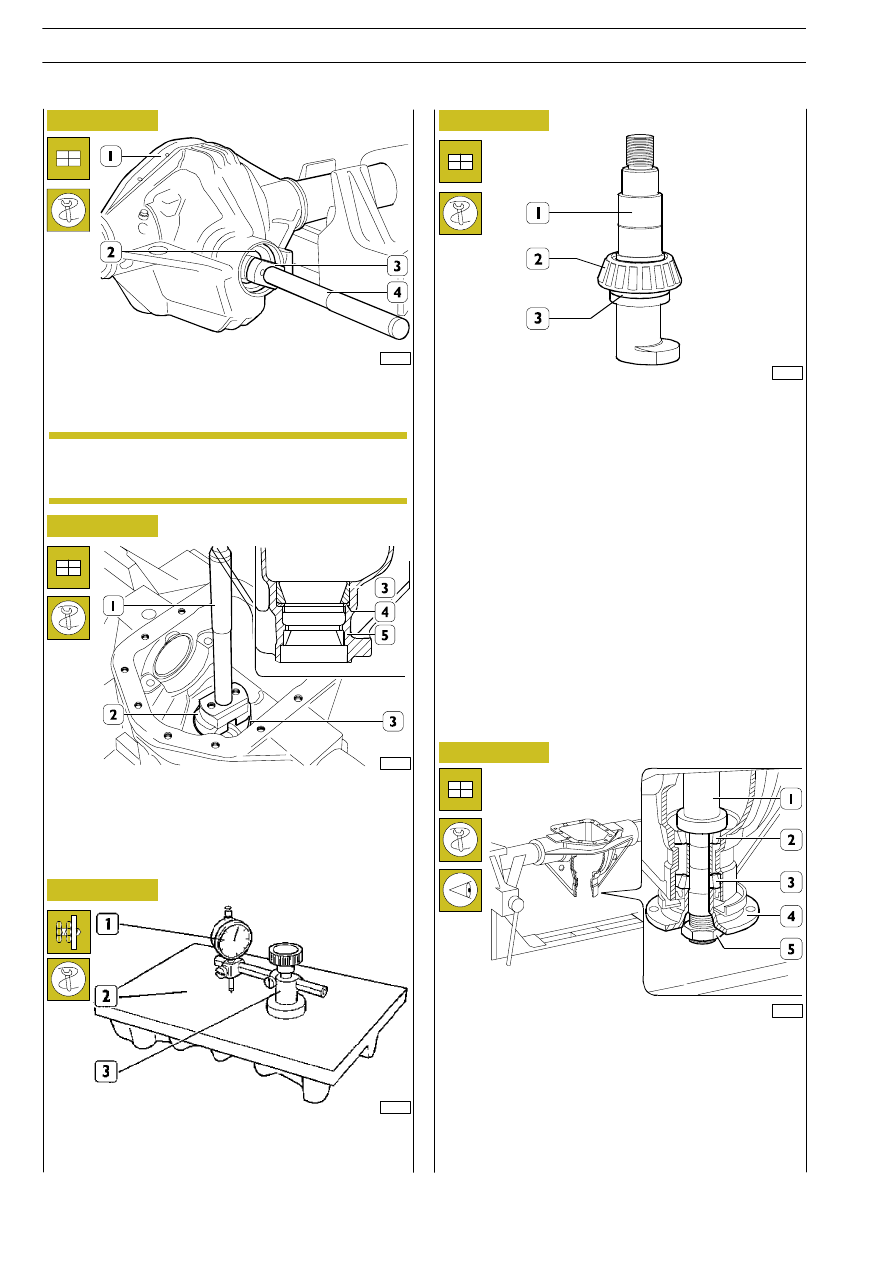
Fit tapered-roller bearing internal ring (2) onto false pinion
99370286 (1) with the washer supplied (3).

Position the dummy pinion 99370286 (1), assembled as
shown in Figure 50, on the external ring (2) of the tapered
roller bearing.
On the opposite side, fit the taper bearing internal ring (3)
on the dummy pinion (1) and the transmission shaft flange
(4) .

Screw on the nut (5) so that the dummy pinion turns freely
with no end float.

Assembling the bevel pinion assembly

New bearings are lubricated with rustproof oil and
must therefore not be washed or heated for
assembly.

NOTE

101977

112

REAR AXLES 450310

D

AILY

Revi - February 2005

Fit the mounting 99395728 (2) with the dial gauge (1) on the
dummy pinion 99370286 (3).

Orientate the, previously zeroed, dial gauge so as to position
the rod on the lowest portion of the seat of the bearing
supporting the gear housing and note the difference A1.

Repeat the same operation on the seat of the other bearing
and note the difference A2.

Thickness to be added to adjusting ring thickness (4,
Figure 54) used for measuring, for pinion positioning is
obtained by the following formula:

51840

18246

51838

A1 indicates the value measured on the right-hand seat.
A2 indicates the value measured on the left-hand seat.
indicates the value marked on the bevel pinion (see
Figure 53).
For example:

Unscrew the retaining nut, the transmission connection
flange and remove it and the bearing from the dummy pinion.

Remove the dummy pinion with the mounting 99395728,
dial gauge and rear bearing from the axle housing.

If required, replace adjusting ring (4) with a new one having
the calculated thickness, after removing bearing outer ring
(3) from rear axle casing (5) by beater.

Then fit the new adjusting ring (4) into rear axle casing (5).

Using the punch 99374092 (2) and grip 99370007 (1), mount
the external ring (3) of the tapered roller bearing.

= A1 + A2

2

− ( B)

S

= 1.05 + 1.10

2

− (− 0.05) = 2.15

2 +

0.05

=

S

Figure 52

Figure 53

Figure 54

If the value marked on the pinion is preceded by a
positive sign (+), it must be subtracted from the
value of the sum divided by two for both seats,
whereas it has to be added if it is preceded by a
negative sign (-).

NOTE

1,125

The result of the formula must be added algebraically to the
value of the adjusting ring used to make the measurements.
Example:
if the value of the adjusting ring used is 3.00 mm, replace with
one measuring 4.125 mm (3.00 + 1.125).

REAR AXLES 450310

113

D

AILY

Revi - February 2005

Position the fixed spacer (3) and the adjustment ring (2), used
previously to obtain the required rolling torque, on the bevel
pinion (1).

18251

18252

62097

Figure 55

Figure 56

Figure 57

Using a suitable punch (1) and a hydraulic press, mount the
internal ring (2) of the tapered roller bearing on the bevel
pinion (3).

Position the axle casing as indicated in the figure.
Fit the taper bearing internal ring (1) and the transmission
shaft flange (2).
Position a suitable pipe (3) on the stand so that the flange (2)
and the taper bearing internal ring (1) are correctly
supported.

Use tool 99370317 (2) to prevent the flange (1) from
rotating.

Tighten the bevel pinion retainer nut to the required torque
with a torque wrench (3).

Mount the bevel pinion (1) in the axle housing so as to enter
the internal ring (2) of the tapered roller bearing.

Tap on the end of the pinion (1) so that the transmission shaft
flange retaining nut (3) can be fitted.

51845

51846

Figure 58

Figure 59

114

REAR AXLES 450310

D

AILY

Revi - February 2005

102972

74728

Figure 60

Using the torque wrench 99389819 (1), measure the rolling
torque of the bevel pinion.

If the reading differs from the prescribed value, disassemble
the pinion (1, Figure 58), replace the adjuster ring (2,
Figure 56) with a ring of the correct thickness.

Refit the pinion and repeat the rolling torque check.

Figure 61

Assembly of differential unit

Fit the differential (1) unit and support (6) bearings in the axle
casing.

Refit the spacers and adjuster rings in exactly the original
positions and in the following order: adjuster ring (2), spacer
(3 and 5) and adjuster ring (4).

Figure 62

51849

Screw on the screws (1) and tighten them to the required
torque with the dynamometric wrench (3).

74728

Figure 63

Check the total rolling torque with the torque wrench
99389819 (1).

If the value of the measurement is not as required, replace
the adjustment rings (2 and 4, Figure 61) with another one
of a suitable thickness.

The rolling torque must be measured at an ambient
temperature of 25

°C, making the pinion turn at a

speed of 50 rpm after it has made 10 turns.

NOTE

Position the caps (2) making the marks made
during disassembly coincide.

NOTE

The rolling torque must be measured at an ambient
temperature of 25

°C, making the pinion turn at a

speed of 50 rpm after it has made 10 turns.

NOTE

When fitting the differential unit, carefully comply
with the tightening torque values specified, and
make use of a torque wrench.

NOTE

REAR AXLES 450310

115

D

AILY

Revi - February 2005


Content   ..  256  257  258  259   ..