Iveco Daily. Manual - part 257
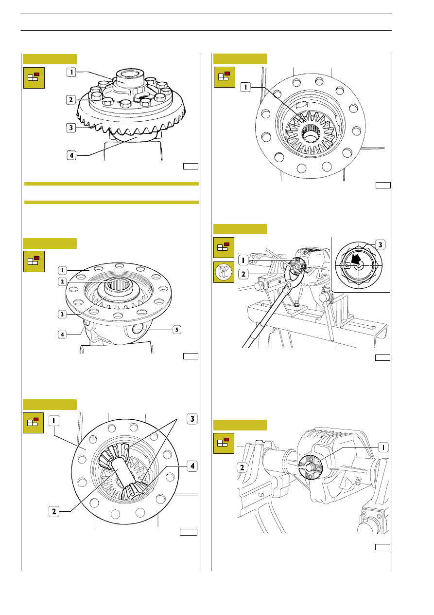
Figure 31
Figure 32
Figure 33
Figure 34
Figure 35
62099
18222
Loosen screws (2), remove ring bevel gear (3) and gear
housing (4) cover (1).
Remove from gear housing (1) the sun gear (2) on cover side
including shoulder washer (3).
Mark cover (1) and gear housing (4).
NOTE
18226
Take planetary gear (1), complete with shoulder washer, out
of the wheel-case.
101974
Take pin (2) out of wheel-case (1), then remove the two
planetary gears (3), complete with shoulder washers (4),
from the wheel-case.
Raise the securing ring (
⇒) on the flange (1) nut (3).
Using tool 99370317 (2), block rotation of the coupling (1).
Remove the nut (3).
51824
51825
Figure 36
Take flange (1) off bevel pinion (2).
108
REAR AXLES 450310
D
AILY
Revi - February 2005