Iveco Daily. Manual - part 97
62386
50676
75461
75942
Figure 146
Figure 147
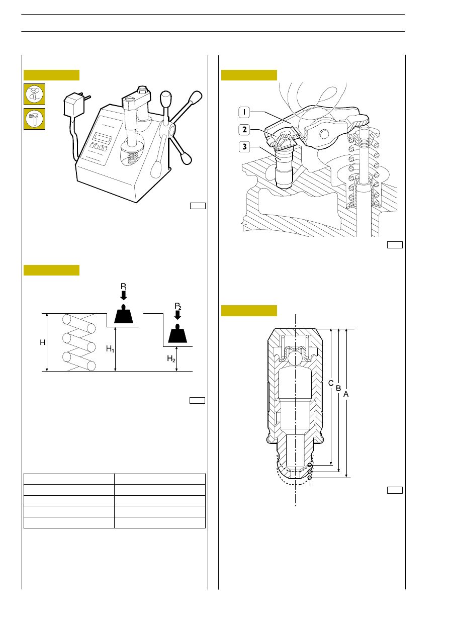
Figure 148
Figure 149
Before assembly, check the flexibility of the valve springs with
the tool 99305047. Compare the load and elastic
deformation data with those of the new springs given in the
following figures.
MAIN DATA TO CHECK INTAKE AND EXHAUST
VALVE SPRINGS
COMPLETE ROCKER ARM ASSEMBLY
The rocker arm assembly is composed of the rocker arm (1),
hydraulic tappet (3), made integral with each other by the clip
(2).
540665
VALVE SPRINGS
ROCKER ARMS — TAPPETS
CROSS-SECTION OF THE HYDRAULIC TAPPET
A = 32.44
±0.3, end of stroke
B = 31.30, working position
C = 29.75
±0.25, start of stroke
F1A ENGINE
D
AILY
366
Base - May 2004
Height
Under a load of
mm
kg
H 54
Free
H1 45
P 243
±12
H2 35
P1 533
±24