Iveco Daily Euro 4. Manual - part 58


  Index      Iveco     Iveco Daily Euro 4 - service repair manual 2006 year


Search            


Content   ..  56  57  58  59   ..


Iveco Daily Euro 4. Manual - part 58


107714

107716

107715

107717

107718

107719

Figure 73

Figure 74

Figure 75

Figure 76

Figure 77

Figure 78

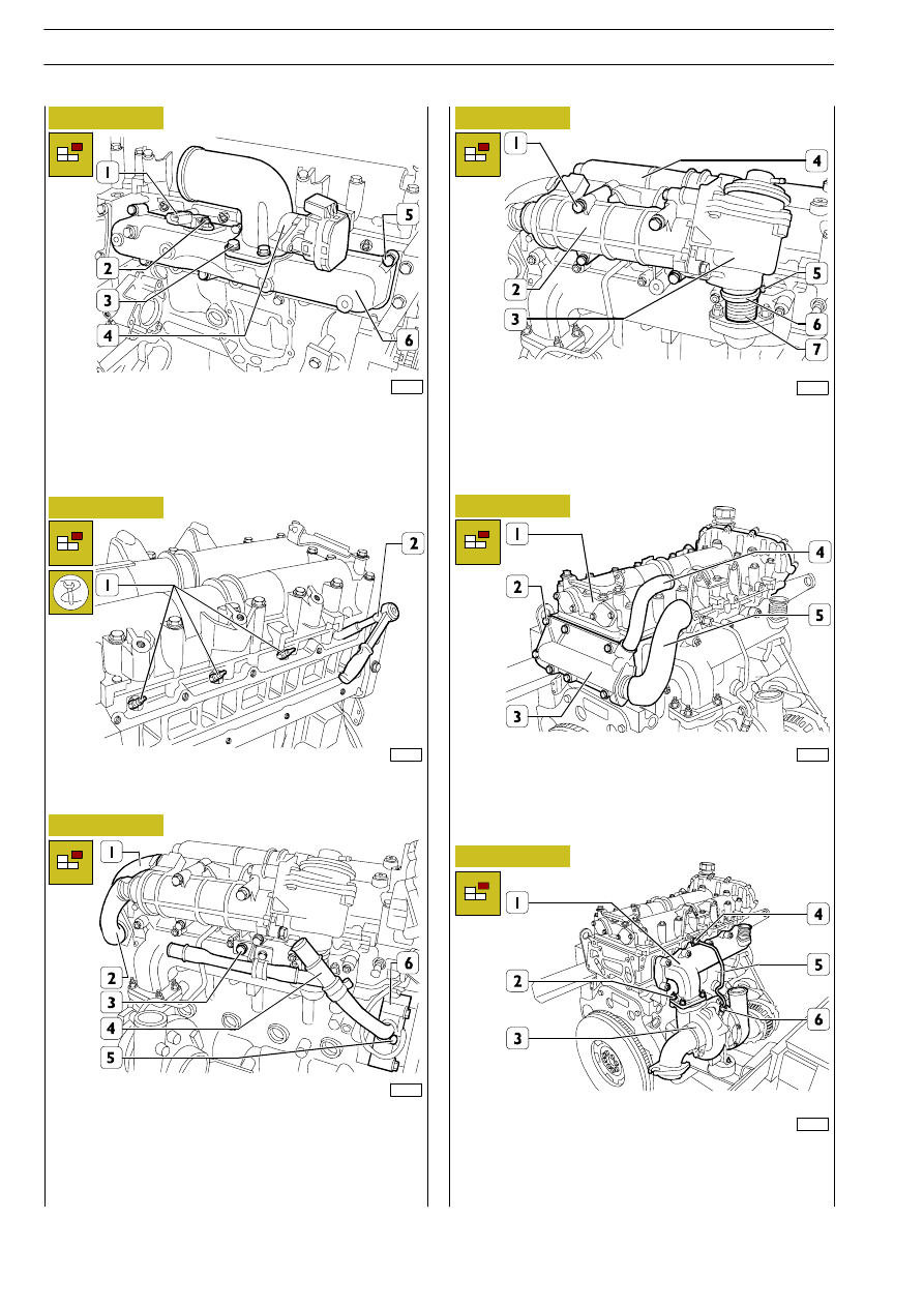
Remove screws (3), then remove throttle valve assembly (4).
Remove the screw (2) and take off the air temperature and
pressure sensor (1).
Remove the screws (5) and take off the suction manifold (6)
with the relevant gasket.

Using wrench SP.2275 (3), remove the glow plugs (4).

Remove the retaining straps, then remove coolant pipes (1
and 2).
Remove screw (3) and strap (5), then disconnect coolant
pipe (4) from water pump (6).

Loosen screw (5), then remove strap (6).
Remove screws (1), then take heat exchanger (2), together
with EGR valve (3), off overhead (4) and connecting pipe (7).

Remove screws (2), then take cover (3), together with pipes
(4 and 5), off cylinder head (1).

Unscrew connections (2, 4 and 6), then disconnect oil pipe
(5).
Remove nuts (2), then take turboblower (3), together with
its respective gasket, off exhaust manifold (1).

224

F1C ENGINE

D

AILY

E

URO

4

88255

107721

107720

107722

88260

107723

Figure 79

Figure 80

Figure 81

Figure 82

Figure 83

Figure 84

Using the specific wrench on the automatic tightener (2),
slacken the tension of the belt (1) and remove it.

Take out the screw (2) and remove the automatic tightener
(1).

Remove the screw (2), the bolt (4) and pull the alternator (3)
out of the support (1).

Remove the screws (1) and take off the support (2) from the
cylinder block.

Use the suitable wrench to remove the oil level sensor (1).
Remove the fastening screw and the rev sensor (2).

Remove the nuts (2), the spacers (1) and take off the exhaust
manifold (3) with the relevant gasket from the cylinder head.

F1C ENGINE

225

D

AILY

E

URO

107724

107726

107725

107727

107728

88265

Figure 86

Figure 87

Figure 88

Figure 89

Figure 90

Figure 85

Secure water pump shaft (5) by means of an Allen wrench
(3) and a special lever. Use a suitable wrench (4) to remove
nut (2) securing hub (1) to shaft (5).

Disassemble hub (5) and pulley (4).
Disconnect electric cable (1) from the retaining clip, then
remove nuts (2) and take electromagnet (3) off water pump
(6).

Remove screws (1), then take water pump (2) off.
Remove screw (3), then take oil dipstick pipe (4) out of front
cover (5).

Remove the screws (3) and the cover (4). Take off the snap
ring (2). Pull out the centrifugal filter (1).

Stop the rotation of the engine flywheel (2) by means of tool
99360306 (1).

Remove the screw (2) and the damper pulley (1).

Slacken the nut (2) anticlockwise because its
threading is left-handed.

The centrifugal filter (1) and the seal ring of the
cover (4) must be changed at every removal.

NOTE

NOTE

226

F1C ENGINE

D

AILY

E

URO

4

88266

88268

107729

88269

88270

Figure 91

Figure 92

Figure 93

Remove the screws (1) and the distribution cover (2).

Remove the nut (1) and the phase sensor (2).
Remove the nuts (3) and the cover (4).

Remove the hydraulic chain tightener: top (1) and lower (2).
Remove the pin (4) and disassemble the mobile skid: lower
(5) and top (3).

Remove the screw (3), the washer (2) and the gear (1).
Remove the screw (7), the washer (6), the gear (5) and the
chain (4).

Remove the cap (4), the screws (2 and 3) and the top fixed
skid (1).

88271

Remove the screws (3) and disassemble the depressor/oil
pump unit (2).
Remove the connection key (1).

Figure 94

Tool 99340059 (4) is used to remove the seal ring
(3) from the cover (2) when the engine is installed
on the vehicle.

Upper hydraulic chain stretcher (1) is equipped with
an anti-return device that makes it necessary to
replace the chain stretcher every time it is
disassembled.

Figure 95

Figure 96

NOTE

NOTE

F1C ENGINE

227

D

AILY

E

URO


Content   ..  56  57  58  59   ..