Engines Iveco N45, N67. Manual - part 30
70326
18625
18882
70327
Figure 75
Figure 76
Figure 77
Figure 78
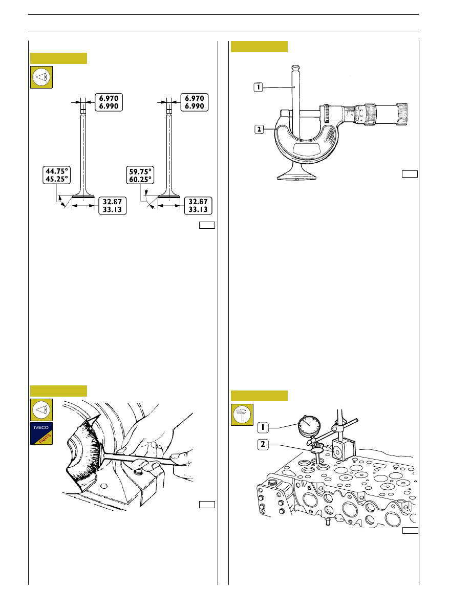
VALVES
INTAKE AND EXHAUST VALVE MAIN DATA
Remove carbon deposits from valves using the proper metal
brush.
Check that the valves show no signs of seizing, scoring or
cracking.
Regrind the valve seats, if required, using tool 99305018 and
removing as less material as possible.
Check the valve stem (1) using a micrometer (2), it shall be
6.970
÷ 6.999.
Use a magnetic base dial gauge (1) set as shown in the figure,
the assembling clearance shall be 0.052
÷ 0.092 mm.
Turn the valve (2) and check that the centering error is not
exceeding 0.03 mm.
Removing carbon deposits, checking and
grinding valves
Checking clearance between valve stem and
valve guide and valve centering
INTAKE
VALVE
EXHAUST
VALVE
34
SECTION 4 - OVERHAUL AND TECHNICAL SPECIFICATIONS
F4HE NEF ENGINES
Base - February 2006
Print P2D32N00GB