Isuzu N-Series. Manual - part 954


  Index      Isuzu     Isuzu N-Series - service repair manual


Search            


Content   ..  952  953  954  955   ..


Isuzu N-Series. Manual - part 954


7B-52 Automatic Transmission (Smoother)

b. Remove the harness from the two clips, and

remove the neutral switch connector from the
bracket. 

c. Remove the six bolts and the gearshift control

box. 

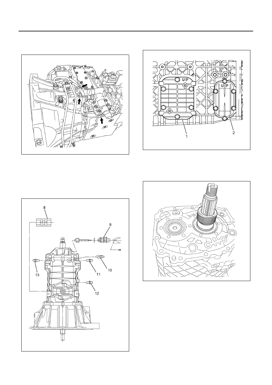
9. Remove the interlock plate (8).

10. Remove the speedometer driven gear (9).
11. Remove the reverse switch (10).
12. Remove the detent assembly (11), (12), (13). 

13. Remove the input shaft speed sensor.

14. Remove the PTO cover (1). 
15. Remove the reverse idle cover (2).

16. Remove the rear cover assembly. 
17. Inspect the rear cover oil seal. If it is worn or

damaged, remove it from the rear cover. 

18. Remove the speedometer gear and collar.

19. Remove the retainer from the transmission case.

N7A1085E

N7A1086E

N7A0312E

N7A1088E

Automatic Transmission (Smoother) 7B-53

20. Pull out the reverse idle shaft, and remove the

reverse idle gear and needle bearing. 

21. Remove the rear outer snap ring from the main

shaft rear bearing. 

22. Remover the counter shim. 
23. Remove the transmission case from the clutch

housing. 

24. Remove the bearing rear outer race from the

transmission case.

25. Remove the 3rd — 4th shift rod, 4th — 5th main

shift rod block and 4th — 5th gear sub shaft block. 

• When driving out the spring pin, insert a round

bar on the opposite side of the shift rod, and
use a spring pin remover to remove the spring
pin while taking care to avoid damage to other
parts. 

26. Remove the 1st — Reverse and 2nd — 3rd shift

rod, 1st — Reverse shift arm, 2nd — 3rd shift arm,
1st — Reverse shift block, 4th — 5th shift arm. 

• When driving out the spring pin, insert a round

bar on the opposite side of the shift rod, and
use a spring pin remover to remove the spring
pin while taking care to avoid damage to other
parts. 

27. Use a remover (5-8840-2755-0) to remove the

bushing from the 2nd — 3rd shift arm. 

28. Use a remover (5-8840-2755-0) to remove the

bushing from the 4th — 5th shift arm.

• Use the remover in combination with a round

bar of a length that makes it possible to push in
as far as possible. 

N7A1090E

N7A0316E

N7A1092E

N7A1093E

7B-54 Automatic Transmission (Smoother)

29. Remove the 5th relay lever from the clutch

housing. 

30. Remove the magnet case from the clutch housing. 
31. Remove the main shaft assembly, top gear shaft

assembly, and counter shaft assembly. 
a. Use a lashing belt or some other belt from a

lashing device to bundle the main shaft
assembly, counter shaft assembly, and top
gear shaft assembly at two points so they
cannot separate. Tighten the belt securely. 

b. Attach a bearing remover to the main shaft and

secure with a lock nut, attach a wire, and raise
it using a hoist. While opening the top gear
shaft bearing outer snap ring attached to the
clutching housing, simultaneously remove the
top gear shaft assembly, main shaft assembly,
and counter shaft assembly from the clutch
housing. 

32. Inspect the clutch housing bushing. If it is worn or

damaged, use pliers to remove it from the clutch
housing. 

N7A1094E

N7A1095E

N7A1096E

N7A1097E

N7A1098E

Automatic Transmission (Smoother) 7B-55

33. Inspect the counter shaft front bearing. If it is worn

or damaged, use a bearing remover (5-8840-2757-
0) and bushing puller (5-8840-2802-0) to remove
the bearing outer race from the clutch housing. 

34. Inspect the front oil seal. If it is worn or damaged,

remove it from the clutch housing. 

Inspect each part. Replace or repair as required if
anything is worn or damaged or if any other defect is
discovered. 
35. Inspect each shift mechanism component. Repair

any minor damage, bending, or stepped wear.
Replace any component that is badly damaged or
worn, and any component that exceeds the
allowable limit. 

• Shift rod and shift arm bending, wear, damage 
• Shift arm thickness 

– Use a micrometer to measure the thickness

of the shift arm tip.

36. Inspect the speedometer driven gear and driven

gear bushing for wear. 

• Replace if there is excessive wear.

Assembly

1. Inspect the oil seal. If it needs to be replaced with

a new one due to wear or damage, apply engine oil
or grease to the oil seal’s outer circumference, and
then use an installer (5-8840-2756-0) and grip (5-
8840-0007-0) to press-fit it into the clutch housing
as shown in the illustration, taking care that the
front-back orientation of the front oil seal is correct. 

• Fill the lip of the oil seal with Besco L2 grease. 

Caution:
Take care to avoid damaging the oil seal lip. 

Shift Arm Thickness (mm)

Specified Value

Limit

1st — Reverse

3rd — 2nd

5th — 4th

9.60 — 9.85

9.0

N7A1099E

N7A1100E

N7A1101E


Content   ..  952  953  954  955   ..