Isuzu N-Series. Manual - part 884


  Index      Isuzu     Isuzu N-Series - service repair manual


Search            


Content   ..  882  883  884  885   ..


Isuzu N-Series. Manual - part 884


7C-12 CLUTCH (FOR MZZ TRANSMISSION)

6. Shift block and release bearing.
7. Return spring.

• Apply the MoS

2

 contained type grease to shift fork

and shift block surfaces.

• Install the return spring (1).

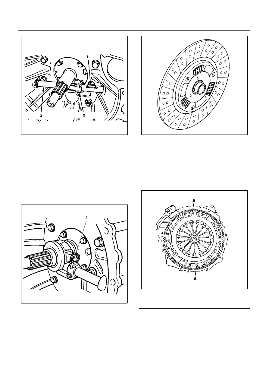
8. Clutch disc assembly.

• Clutch pilot aligner 5-8840-2790-0 into the center

of the clutch disc assembly.

9. Pressure plate assembly.

• Install the pressure plate assembly to the flywheel.

If the pressure plate was replaced to new parts, be
sure to remove the ring which is installed to the di-
aphragm spring.

Tighten:
Pressure plate bolt to 40 N

⋅m (4.1 kg⋅m / 30 lb⋅ft) in the

sequence shown in the figure.

• Remove the pilot aligner.

10. Transmission assembly.

• Refer to TRANSMISSION in this manual.

Legend

1. Key
2. Shift fork
3. Clutch shaft

N7A0557E

N7A0558E

Legend

A. Dowel pin

N7A0546E

N7A0498E

CLUTCH (FOR MZZ TRANSMISSION) 7C-13

Clutch Controls

Clutch Control Assembly

Remove or Disconnect

• Drain the clutch fluid from the clutch hydraulic line.

Notice:
Do not let clutch fluid remain on a painted surface. Wash
it off immediately.

1. Meter cluster and meter assembly.

• Pull out the meter cluster and disconnect harness

connectors.
Refer to INSTRUMENTAL PANEL.

2. Electric vacuum pump.

• Remove the electric vacuum pump.

Refer to ELECTRIC VACUUM PUMP.

3. Hose and pipe.
4. Clutch pedal and bracket assembly.
5. Clutch switch.
6. Clevis pin.
7. Master cylinder.
8. Return spring.

Legend

1. Hose and pipe

6. Return spring

2. Clutch pedal and bracket assembly

7. Fulcrum pin

3. Clutch switch

8. Clutch pedal

4. Clevis pin

9. Flexible hose

5. Master cylinder

10. Slave cylinder

N7A0560E

7C-14 CLUTCH (FOR MZZ TRANSMISSION)

9. Fulcrum pin.

10. Clutch pedal.
11. Flexible hose.
12. Slave cylinder.

Inspect

• All parts for damage or wear.
• The clearance between the pedal shaft and bush-

ings.

• Replace the clutch pedal assembly if the clearance

is excessive.

Install or Connect

Notice:
For steps 1, 7 and 9 see “Notice” on page 7C-2 of this
section.

1. Slave cylinder.

Tighten:
Slave cylinder bolt to 19 N

⋅m (1.9 kg⋅m / 14 lb⋅ft).

2. Flexible hose.

Tighten:
Flexible hose tube nut to 20 N

⋅m (2 kg⋅m / 14 lb⋅ft).

3. Clutch pedal.
4. Fulcrum pin.
5. Return spring.
6. Master cylinder.

Adjust:

• Loosen the jam nut on the master cylinder push

rod.

• Adjust push rod length to 156.5 — 157.5mm (6.16

— 6.20 in), and tighten the jam nut.

Tighten:
Master cylinder jam nut to 17 N

⋅m (1.7 kg⋅m / 148 lb⋅in).

7. Clutch switch.
8. Clutch pedal and bracket assembly.

Tighten:
Clutch pedal and bracket bolt to 37 N

⋅m (3.8 kg⋅m / 27

lb

⋅ft).

9. Hose and pipe.

10. Electric vacuum pump.

• Refer to ELECTRIC VACUUM PUMP.

11. Meter cluster and meter assembly.

• Refer to INSTRUMENTAL PANEL.

12. Bleed the clutch hydraulic circuit. Refer to BLEED-

ING CLUTCH HYDRAULIC CIRCUITS previously
in this section.

CLUTCH (FOR MZZ TRANSMISSION) 7C-15

UNIT REPAIR

Master Cylinder

Master Cylinder Assembly

Disassembly

1. Hose joint (1).
2. Dust cover (5).
3. Snap ring (4).
4. Piston assembly (3).
5. Cylinder body (2).

Clean

• All disassembled parts in brake fluid. Be sure to

check the ports for restrictions. Use a metal wire to
loosen the dirt.

Inspect

• Cylinder bore and piston for wear and rust forma-

tion.

• Spring for weakening.
• Replace any parts if wear, damage, or any other

abnormal conditions are found during inspection.

Measure

• The bore inside the master cylinder body with a dial

indicator. Use a micrometer to check the thickness
of the piston. Replace the master cylinder body or
piston if the clearance is less than 0.12 mm
(0.0047 in).

Legend

1. Hose joint

4. Snap ring

2. Cylinder body

5. Dust cover

3. Piston assembly

6. Push rod

N7A0561E


Content   ..  882  883  884  885   ..