Isuzu N-Series. Manual - part 885


  Index      Isuzu     Isuzu N-Series - service repair manual


Search            


Content   ..  883  884  885  886   ..


Isuzu N-Series. Manual - part 885


7C-16 CLUTCH (FOR MZZ TRANSMISSION)
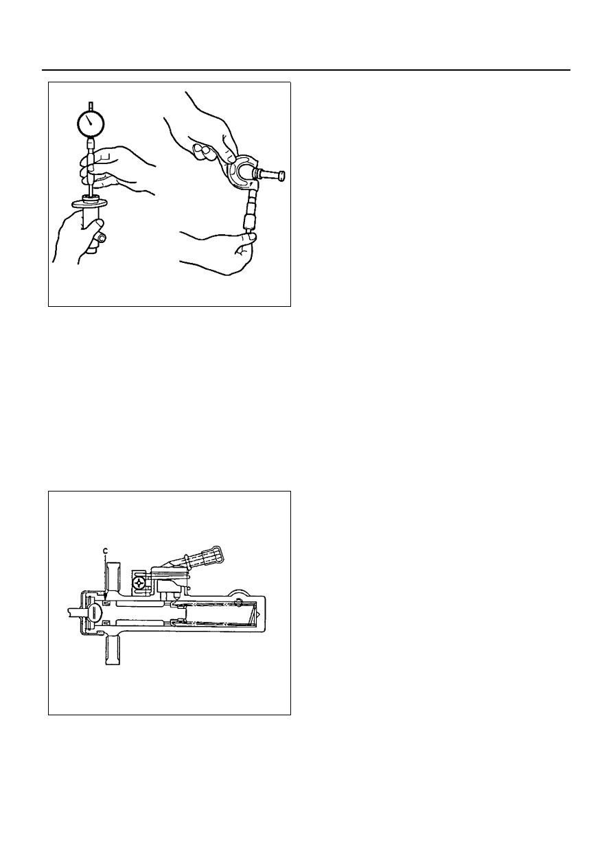
Reassembly

1. Cylinder body (2).

Important:

• Before installing the parts, apply a thin coat of

brake fluid.

2. Piston assembly (3). Install new cup (C) in groove

in piston with the lip turned toward the front of the
cylinder body. Use care so as not to scratch the
lipped portion of the cup.

3. Snap ring (4) to the cylinder body groove.
4. Dust cover (5).
5. Hose joint (1).

N7A0513E

N7A0563E

CLUTCH (FOR MZZ TRANSMISSION) 7C-17

Slave Cylinder

Slave Cylinder Assembly

Disassembly

1. Push rod (1).
2. Boot (2).
3. Piston assembly (3).
4. Slave cylinder body (4).
5. Bleeder screw and cap (5).

Clean

• All disassembled parts in brake fluid. Be sure to

wipe excess brake fluid from the components.

Inspect

• Cylinder bore and piston for wear and rust forma-

tion.

• Spring for weakening.
• Piston cups for wear, deterioration and scratches.
• Replace any parts if wear, damage, or any other

abnormal conditions are found during inspection.

Measure

• The clearance inside the slave cylinder body with a

dial indicator. Use a micrometer to check the thick-
ness of the piston. Replace the slave cylinder body
or piston if the clearance is less than 0.11 mm
(0.0043 in).

Reassembly

1. Slave cylinder body (4).

Notice:
See “Notice” on page 7C-2 of this section.

2. Bleeder screw and cap (5).

Tighten:
Bleeder screw to 8 N

⋅m (0.8 kg⋅m / 69 lb⋅in).

Important:

• Before installing the parts, apply a thin coat of

brake fluid.

Legend

1. Push rod

4. Slave cylinder body

2. Boot

5. Bleeder screw and cap

3. Piston assembly

5

4

3

2

1

N7A0564E

N7A0562E

7C-18 CLUTCH (FOR MZZ TRANSMISSION)

• Be sure to install the piston cup in the piston

groove with the lip turned toward the front of the
cylinder body. Use care so as not to scratch the lip
portion of the piston cup.

3. Piston assembly (3).
4. Boot (2).
5. Push rod (1).

CLUTCH (FOR MZZ TRANSMISSION) 7C-19

SPECIFICATIONS

Specifications

Fixing Torque

Pressure Plate Types

Dry Single Plate w/Cushioning Spring

Clearance Between Master Cylinder Body and Piston

0.12 mm (0.0047 in)

Clearance Between Slave Cylinder Body and Piston

0.11 mm (0.0043 in)

Driven Plate Warpage Maximum Limit 

0.6 mm (0.024 in)

Clutch Size

325 mm (12.80 in)

Depression of Rivet Head Maximum Limit 

0.2 mm (0.008 in)

Pressure Plate Clamping Force Maximum Limit 

970 kg (2,139 lb)

Pressure Plate Finger Height

 61.8 — 63.8 mm (2.43 — 2.51 in)

Master Cylinder Push Rod Length

(From Center of Crevis Pin Hole to Mounting Surface)

156.5 — 157.5 mm (6.16 — 6.20 in)

Pedal Height (Reference)

160 — 170 mm (6.3 — 6.7 in)

Pedal Travel (Reference)

159 — 169 mm (6.2 — 6.7 in)

Free Play (Reference)

15 — 25 mm (0.6 — 1.0 in)

Clutch Switch Clearance

0.5 — 1.0 mm (0.020 — 0.039 in)

Master Cylinder Push Rod Jam Nut

17 N

⋅m (1.7 kg⋅m / 148 lb⋅in)

Clutch Switch Jam Nut 

15 N

⋅m (1.5 kg⋅m / 133 lb⋅in)

Pressure Plate Bolts

40 N

⋅m (4.1 kg⋅m / 30 lb⋅ft)

Master Cylinder Bolts

13 N

⋅m (1.3 kg⋅m / 113 lb⋅in)

Slave Cylinder Bolts

19 N

⋅m (1.9 kg⋅m / 14 lb⋅ft)

Flexible Hose Tube Nuts

20 N

⋅m (2 kg⋅m / 14 lb⋅ft)

Slave Cylinder Bleeder Screw

8 N

⋅m (0.8 kg⋅m / 69 lb⋅in)

Clutch Pedal and Bracket Assembly Mounting Bolt

37 N

⋅m (3.8 kg⋅m / 27 lb⋅ft)


Content   ..  883  884  885  886   ..