Isuzu N-Series. Manual - part 866


  Index      Isuzu     Isuzu N-Series - service repair manual


Search            


Content   ..  864  865  866  867   ..


Isuzu N-Series. Manual - part 866


CLUTCH 7C-13

7. Remove the return spring.
8. Remove the clutch pedal.
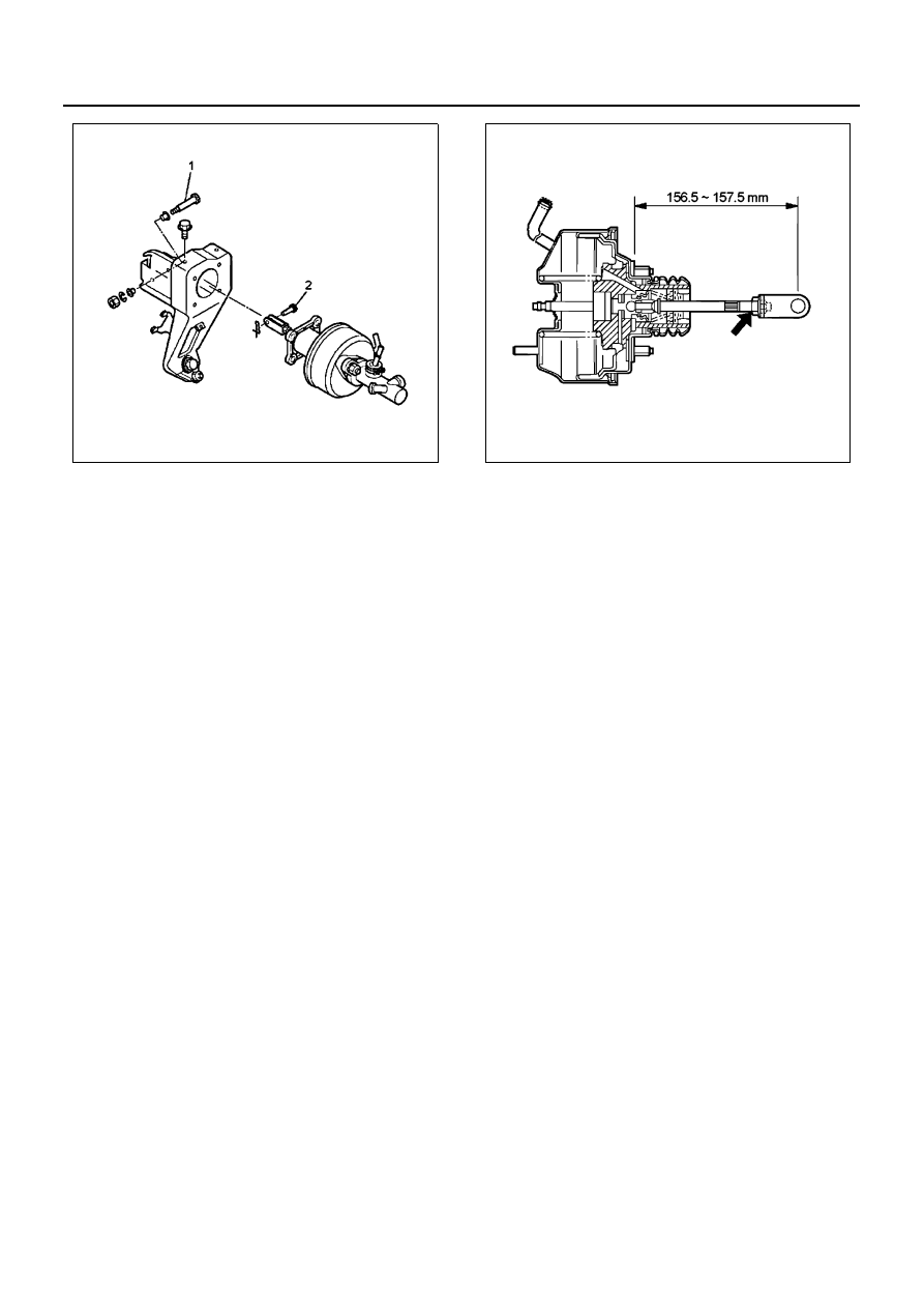
9. Remove the clutch booster & spacer, and master

cylinder assembly.

• Removal of the master cylinder can be done

only by removing the meter cluster.

Inspection

Make necessary adjustment, repairs, and part replace-
ment if excessive wear or damage is found during in-
spection.

Installation

1. Install the clutch booster, spacer and master cylin-

der assembly.

• Tighten the lock nut where the distance be-

tween the center of the clevis pin hole and the
installation surface is 156.5 — 157.5 mm
(6.161 — 6.201 in).

Tighten:
Lock nut to 26 N

⋅m (2.6 kg⋅m / 19 lb⋅ft)

• Install the clutch booster, spacer and master

cylinder assembly to the clutch pedal bracket.

Tighten:
Nut to 13 N

⋅m (1.3 kg⋅m / 10 lb⋅ft)

2. Install the pressure switch connector.
3. Install the clutch pedal.
4. Install the return spring.
5. Install the clevis pin.
6. Install the pin.
7. Install the clutch switch.
8. Install the clutch pedal and bracket assembly.

Tighten:
Clutch bracket bolts to 37 N

⋅m (3.8 kg⋅m / 27 lb⋅ft)

• The clutch pedal adjustment is not necessary if

the length of the clutch booster operation rod is
adjusted when installing the clutch booster.
The length of the clutch booster operation rod:
The distance between the installation surface
and the center of the clevis pin hole is 156.5 —
157.5 mm (6.161 — 6.200 in).

• Check the clutch pedal play.
• Adjust the clearance between the pedal and

the clutch switch bolt, to the measured value.

Clutch Pedal Height (A) 
160 — 170 mm (6.299 — 6.693 in) (Reference value)
Pedal Stroke (B)
159 — 169 mm (6.260 — 6.653 in) (Reference value)
Clutch Pedal Play
15 — 25 mm (0.590 — 0.984 in) (Reference value)
Pedal and Clutch Switch
Bolt Clearance (C)
0.5 — 1.0 mm (0.020 — 0.039 in)

N7A0501E

N7A0503E

7C-14 CLUTCH

9. Install the vacuum hose.

10. Install the oil hose and clutch pipe.

Bleeding of Slave Cylinder

• After the installation, make sure to perform the

bleeding of the slave cylinder conforming to the
following procedure.

a. Refill brake fluid to the maximum level of the

reservoir.

b. Connect a vinyl tube to the bleeder screw, and

insert the other end of the vinyl tube into a
transparent container.

c. Pump the clutch pedal several times and hold it

depressed.

d. Loosen the bleeder screw on the clutch slave

cylinder to bleed air in the fluid. Tightening the
bleeder screw, slowly return the clutch pedal.

e. Repeat steps (c) and (d) until the air in the fluid

is completely bled.

f. After bleeding the air, securely tighten the

bleeder screw and install the bleeder cap.

g. Refill brake fluid to the maximum level of the

reservoir.

N7A0504E

N7A0011E

CLUTCH 7C-15

UNIT REPAIR

Master Cylinder

Components

Removal

Caution:
Press down the piston with your fingers or shop cloth to
prevent it from jumping out.

1. Remove the pressure switch (3).
2. Remove the hose joint (1).
3. Remove the dust cover (6).
4. Remove the snap ring (5).
5. Remove the piston assembly (4).
6. Remove the cylinder body (2).

Inspection

Make the necessary adjustments, repairs, and parts re-
placements if excessive wear or damage is found during
inspection.
Cylinder body

• Check the fluid return port for clogging.

Internal parts

• Replace the parts indicated in the figure with new

ones.

Clearance of cylinder body and piston

• Check the cylinder body for stepped wear, corro-

sion and damage, and measure the inside diame-
ter.

Cylinder body inside diameter
Standard : Limit 

φ20.64 mm (0.8126 in)

• Check the piston for damage, rust and wear.
• Measure the clearance between the cylinder body

and the piston.

Clearance between cylinder body and piston
Standard : 0.03 — 0.11 mm (0.0012 — 0.0043 in)
Limit : 0.12 mm (0.0047 in)

Legend

1. Hose joint

5. Snap ring

2. Cylinder body

6. Dust cover

3. Pressure switch

7. Damper Cylinder

4. Piston assembly

8. Washer

N7A0505E

7C-16 CLUTCH

• If the wear limit is exceeded, replace the master

cylinder assembly with a new one.

Installation

1. Cylinder body

• Immerse the cylinder body in clean brake fluid.

2. Install the piston of the piston assembly after apply-

ing rubber grease.

Caution:
Do not damage the piston assembly when installing.

3. Install the snap ring.
4. Install the dust cover.
5. Install the hose joint.

Tighten:
Hose joint to 4.5 N

⋅m (0.45 kg⋅m / 3.25 lb⋅ft)

6. Install the pressure switch.

• Apply liquid gasket to the switch screw, and in-

stall to the master cylinder.

Liquid Gasket : LOCTITE 575

Tighten:
Pressure switch to 2.5 N

⋅m (0.25 kg⋅m / 1.81 lb⋅ft)

N7A0506E


Content   ..  864  865  866  867   ..