Isuzu N-Series. Manual - part 842


  Index      Isuzu     Isuzu N-Series - service repair manual


Search            


Content   ..  840  841  842  843   ..


Isuzu N-Series. Manual - part 842


MANUAL TRANSMISSION 7B-29

Disassembly

Caution:
Be careful not to damage the transmission case and the
clutch housing because they are made of aluminum.
Further attention should be paid to the rib because its
damage weakens hardness of the case.
Do not hurt yourself when working on something heavy
such as cases and gears.

1. Remove the shift block assembly.

• Refer to CLUTCH.

2. Remove the shift fork and the support bolt.

• Refer to CLUTCH.

3. Remove the bolt securing the adjust hole cover

and remove the parking brake drum.

• Refer to PARKING BRAKE ASSEMBLY.

4. Raise the caulking portion (2 parts) of the coupling

driver lock nut securely, and then remove the lock
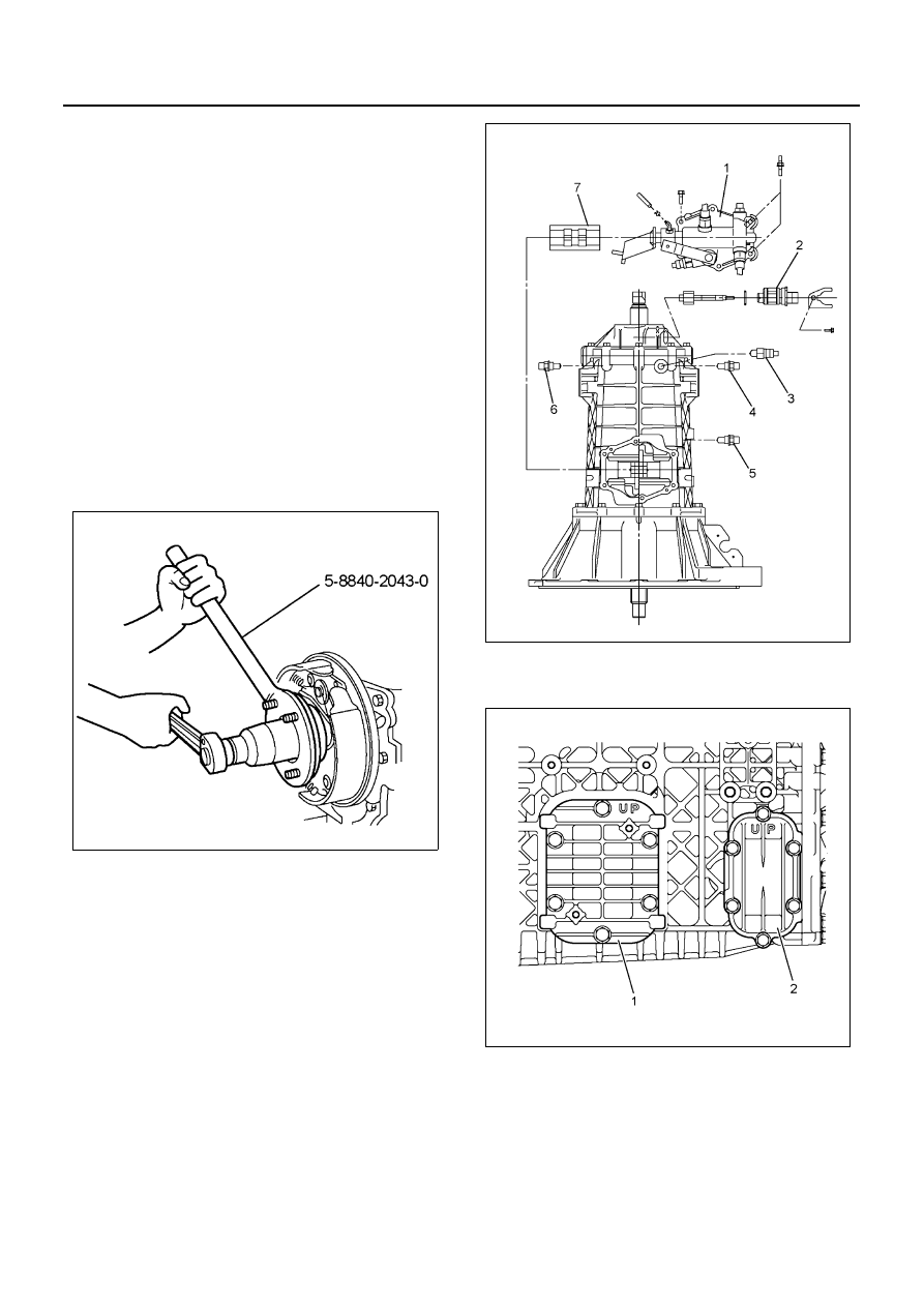
nut using the flange holder 5-8840-2043-0.

5. Remove the coupling driver and O-ring.
6. Remove the parking brake assembly.

• Refer to PARKING BRAKE ASSEMBLY.

7. Remove the filler plug and O-ring.
8. Remove the drain plug and O-ring.

• Drain the transmission oil. Check the amount of

oil and the existence of metal particles and for-
eign matters while draining oil.

9. Remove the speedometer driven gear (2).

10. Remove the reverse switch (3).
11. Remove the detent assembly (4)(5)(6).
12. Remove the control box (1) and the interlock plate

(7).

13. Remove the PTO cover (1).
14. Remove the reverse idle cover (2).

15. Remove the rear cover assembly.
16. If worn or damaged parts are found after checking

the rear cover oil seal, remove the oil seal from rear
cover using the flat-tip screwdriver.

17. Remove the speedometer gear and collar.

N7A0294E

N7A0311E

N7A0312E

7B-30 MANUAL TRANSMISSION

18. Remove the main shaft end lock nut using the

wrench 5-8840-2798-0. (4WD model)

19. Remove the retainer from the transmission case.
20. Pull out the reverse idle shaft, and then remove the

reverse idle gear and the needle bearing. 

21. Remove the snap ring from the main shaft rear

bearing.

22. Remove the shim from the counter shaft rear bear-

ing.

23. Remove the transmission case from the clutch

housing.

24. Remove the bearing rear outer race from the trans-

mission case.

25. Remove the 4th-5th shift rod, 4th-5th main shift

block and 4th-5th sub shift block.

• When driving out the spring pin, put a round

pole on the opposite side of the shift rod not to
damage other parts, and then remove the
spring pin using the spring pin remover.

N7A0313E

N7A0314E

N7A1090E

N7A0316E

MANUAL TRANSMISSION 7B-31

26. Remove the 1st-reverse and 2nd-3rd shift rod, 1st-

reverse shift arm, 2nd-3rd shift arm, 1st-reverse
shift block, and 4th-5th shift arm.

• When driving out the spring pin, put a round

pole on the opposite side of the shift rod not to
damage other parts, and then remove the
spring pin using the spring pin remover.

27. Remove the bush from the 2nd-3rd shift arm using

the remover 5-8840-2755-0.

28. Remove the bush from the 4th-5th shift arm using

the remover 5-8840-2755-0.

• Use the remover with a round pole whose

length is enough to push the remover to the
end.

29. Remove the 5th relay lever from the clutch hous-

ing.

30. Remove the magnet from the clutch housing.
31. Remove the main shaft assembly, the top gear

shaft assembly and counter shaft assembly.
a. Tie the main shaft assembly, the counter shaft

assembly and the top gear shaft assembly at
the two positions not to let them come apart us-
ing a lashing belt or other belts with a fixing
function, and then fix them securely.

b. Install the bearing remover to the main shaft

and secure it with a lock nut, hang them with a
hoist and a wire, and then remove the top gear
shaft assembly, the main shaft assembly, the
counter shaft assembly from the clutch housing
as a unit while spreading the top gear shaft
bearing outer snap ring installed to the clutch
housing.

N7A0317E

N7A1093E

N7A1094E

N7A1095E

7B-32 MANUAL TRANSMISSION

32. Check the clutch housing bush, and then remove it

from the clutch housing using a pliers if it is worn or
damaged.

33. Check the front oil seal, and then remove it from

the clutch housing using a flat-tip screwdriver if it is
worn or damaged.

34. Check each part, and then correct and replace it if

some worn, damaged or faulty parts are found.
Check each part of the shift mechanism, and then
correct light damage, deflection or stepped wear.
Replace it when it is heavily damaged or its usage
limit is over.

• Deflection, wear and damage of the shift rod

and the shift arm

• Shift arm thickness

– Measure the thickness of the shift arm tip us-

ing the micrometer.

35. Check the wear of the speedometer driven gear

and the driven gear bush.

• Replace them if they are heavily worn.

N7A1096E

N7A1097E

N7A1098E

Shift arm thickness, mm (in)

Standard

Limit

1st-reverse

3rd-2nd

5th-4th

9.60 — 9.85 

(0.377 — 

0.387)

9.0 (0.354)

N7A1100E


Content   ..  840  841  842  843   ..