Isuzu N-Series. Manual - part 731


  Index      Isuzu     Isuzu N-Series - service repair manual


Search            


Content   ..  729  730  731  732   ..


Isuzu N-Series. Manual - part 731


6E-346    Engine Control System (4HK1) 

4. Install the fuel leak off hose to the fuel leak off pipe.
5. Install the air intake pipe.

Notice:

• Carefully check for fuel leak after starting the

engine.

• After the fuel pressure limiter is replaced, clear the

trouble code and make sure the fuel pressure limiter
operates normally using a scan tool.

Fuel Rail Replacement

Removal Procedure
WARNING:
TO PREVENT LEAKED FUEL FROM CATCHING
FIRE, DO NOT WORK WHILE THE ENGINE IS HOT.

Preparation:

• Pour detergent into a steam cleaner, and throughly

wash around the sensor and the fuel rail.

• Remove water completely using air blow.

Notice:
Make sure that foreign matter will be prevented from
getting in.

1. Remove the air intake pipe.

• Disconnect the connector for the intake air

temperature sensor.

2. Remove the fuel leak off hose from the leak off

pipe.

• Cover the removed fuel hose, keep it facing

upward and secure it using wire, etc.

3. Disconnect the fuel rail pressure sensor harness

connector.

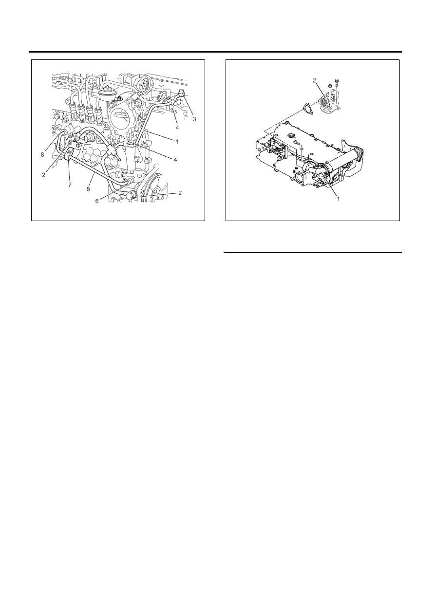
4. Remove the EGR valve and the EGR adapter.
5. Tape the EGR case holes shut to prevent the entry

of foreign material.

Legend

1. EGR Adapter
2. EGR Valve


6. Remove the injection pipe clip and remove the

injection pipes.

Important:
Loosen the injection pipes gradually not to scatter high
pressure fuel.

N6A6386E

N6A6368E

 Engine Control System (4HK1)    6E-347

Legend

1. Fuel Injection Pipe
2. Fuel Injection Pipe Clip


7. Remove the fuel pipe.

Important:
Loosen the fuel pipe gradually not to scatter high
pressure fuel.

8. Remove the clips and the fuel leak off pipe.

Legend

1. Fuel Pipe
2. Fuel Leak-Off Pipe


9. Remove the fuel rail and the fuel rail bracket.

• Do not remove the flow damper. The dampers

should always remain in the fuel rail.

• Take care not to damage the connector unit of

the pressure sensor.

Legend

1. Fuel Rail Bracket
2. Fuel Rail


Disassembly

1. Remove the fuel pressure limiter.
2. Remove the fuel rail pressure sensor.

N6A6128E

N6A6383E

N6A6384E

6E-348    Engine Control System (4HK1) 

Legend

1. Fuel Rail
2. Fuel Rail Pressure Sensor
3. Fuel Pressure Limiter
4. Flow Damper


Reassembly

1. Install the fuel pressure limiter.

Tighten:
Fuel pressure limiter to 172 N

⋅m (17.5 kg⋅m / 127

lb

⋅ft)

2. Install the fuel rail pressure sensor.

Tighten:
Fuel rail pressure sensor to 98 N

⋅m (10 kg⋅m / 72

lb

⋅ft)

Installation Procedure

1. Tighten the fuel rail bracket using the specified

mounting torque.

Tighten:
Nuts to 19 N

⋅m (1.9 kg⋅m / 14 lb⋅ft)

2. Tighten the fuel rail using the specified mounting

torque.

Tighten:
Bolts to 19 N

⋅m (1.9 kg⋅m / 14 lb⋅ft)

Legend

1. Fuel Rail Bracket
2. Fuel Rail


3. Tighten the fuel leak off pipe (1) using the

mounting eyebolt and the clips using the specified
torque.

Tighten:
(2): 18 N

⋅m (1.8 kg⋅m / 13 lb⋅ft)

(3): 12 N

⋅m (1.2 kg⋅m / 9 lb⋅ft)

(4): 8 N

⋅m (0.8 kg⋅m / 69 lb⋅in)

4. Tighten the fuel pipe (5) using the mounting sleeve

nut and the clip using the specified torque.

Tighten:
(6): 44 N

⋅m (4.5 kg⋅m / 33 lb⋅ft)

(7): 6 N

⋅m (0.6 kg⋅m / 52 lb⋅in)

(8): 44 N

⋅m (4.5 kg⋅m / 33 lb⋅ft)

5. Install the fuel leak off hose to the fuel leak off pipe.

1

3

2

4

N6A6385E

N6A6384E

N6A6386E

 Engine Control System (4HK1)    6E-349

6. Tighten the injection pipe and the clip using the

specified mounting torque.

Tighten:
Injection pipe sleeve nut to 44 N

⋅m (4.5 kg⋅m / 33

lb

⋅ft)

Injection pipe clip to 6 N

⋅m (0.6 kg⋅m / 52 lb⋅in)

• Apply a thin coat of engine oil on the periphery

of the sleeve nut on the injector side and
assemble.

Legend

1. Fuel Injection Pipe
2. Fuel Injection Pipe Clip


7. Connect the fuel rail pressure (FRP) sensor

connector.

8. Install the gasket to the EGR valve and tighten the

bolts to the specified torque.

Tighten:
Bolts to 24 N

⋅m (2.4 kg⋅m / 17 lb⋅ft)

9. Install the gasket to the EGR adapter and tighten

the bolts to the specified torque.

Tighten:
Bolts to 24 N

⋅m (2.4 kg⋅m / 17 lb⋅ft)

Legend

1. EGR Adapter
2. EGR Valve Gasket
3. EGR Valve
4. EGR Valve Gasket


10. Install the air intake duct.

• Connect the connector for the intake air

temperature sensor.

Fuel Supply Pump Replacement

Removal Procedure
Important:
The fuel supply pump must be timed to the engine.

1. Remove the intake pipe and the intake throttle

valve.

2. Remove the fuel pipe and fuel leak-off pipe.

N6A6128E

N6A6371E

N6A6121E


Content   ..  729  730  731  732   ..