Isuzu N-Series. Manual - part 614
6C-26 ENGINE FUEL
Notice:
The inline pressure will decrease and needle valve lift
(as indicated on the dial gauge) will also decrease a lit-
tle.
2. Read the needle valve lift ‘liter’ from the dial gauge
indication (once the needle valve has descended
when the second spring has stopped operating).
Refer to the pre-lift measuring point for ‘liter’.
Pre-Lift Measuring Point:
Read the dial gauge at first nozzle opening pressure
+approx 1 MPa (10 kg/cm
2
).
Notice:
This point can be found while the pressure is decreas-
ing.
3. Confirm that pre-lift ‘liter’ is as specified.
4. If pre-lift is not specified, replace the pins, lift piece,
spacer and nozzle assembly with the service kit.
Service kit:
8-9720-3470-1
Legend
A. Inline pressure
1. Needle valve lift
N6A3421E
N6A3422E
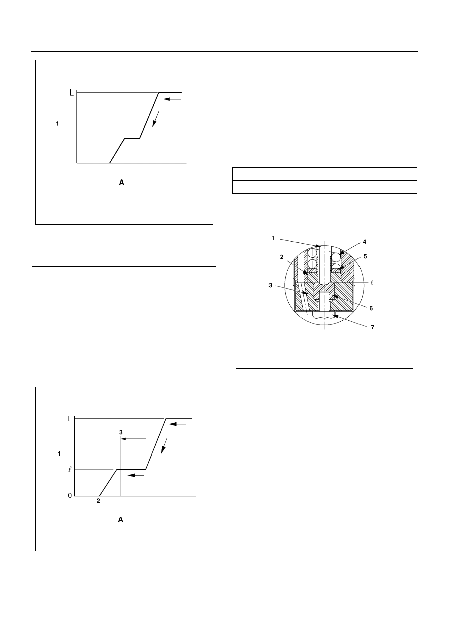
Legend
A. Inline pressure
1. Needle valve lift
2. First nozzle opening pressure
3. Measuring point of pre-lift
Pre-lift
mm (in)
0.04 (0.002)
Legend
1. Push rod
2. Spring seat
3. Spacer
4. Second spring
5. Adjusting shim
6. Lift piece
7. Needle valve
N6A3423E