Isuzu N-Series. Manual - part 601
6A1-92 4JB1/4JB1-TC/4JG2/4JH1-TC - ENGINE
ENGINE ASSEMBLY
Component
Removal
Preparation
• Disconnect battery ground cable.
• Drain coolant.
1. Transmission and Clutch Assembly
• Raise vehicle and support with suitable safely.
1) Propeller Shaft
• Reference mark the flange yoke to the parking
brake drum.
• Disconnect the propeller shaft at flange yoke.
• Put aside the propeller shaft and tie it to the
frame so that it does not interface with servicing
work.
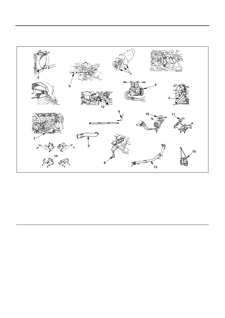
Legend
1. Transmission and clutch assembly
9. A/C Compressor assembly (A/C model)
2. Radiator assembly
10. Power steering pump & bracket assembly (Power
steering model)
3. Intake air duct
4. Heater hose
11. Actuator vacuum hose (Exhaust brake model)
5. Engine control cable
12. Vacuum pump hose
6. Glow plug harness
13. Front exhaust pipe
7. Fuel hose
14. Support rubber
8. Oil pressure switch harness
15. Engine assembly
N6A3358E