Isuzu N-Series. Manual - part 600


  Index      Isuzu     Isuzu N-Series - service repair manual


Search            


Content   ..  598  599  600  601   ..


Isuzu N-Series. Manual - part 600


6A1-88 4JB1/4JB1-TC/4JG2/4JH1-TC - ENGINE

Tighten:

• 167 N

⋅m (17.0 kg⋅m / 123 lb⋅ft)

Notice:
Check to see that the crankshaft turns smoothly by ro-
tating it manually.

2. Crankshaft Rear Oil Seal

Use the oil seal installer to install the oil seal to the
cylinder body.
Rear Oil Seal Installer: 5-8840-2361-0

Notice:
Wipe off rust and scraps clean from the press-in portion
of the oil seal.
Take note of the press-in direction of the oil seal.

1) Install the adapter of the special tool to the rear

end of the crankshaft with two bolts.

2) Install the oil seal to the outer circumference of

the adapter.

3) Insert the slave into the adapter portion, and

tighten it in with the bolt (M12 

× 1.75L = 70) until

the adapter section hits the slave.

4) Remove the adapter and the slave.
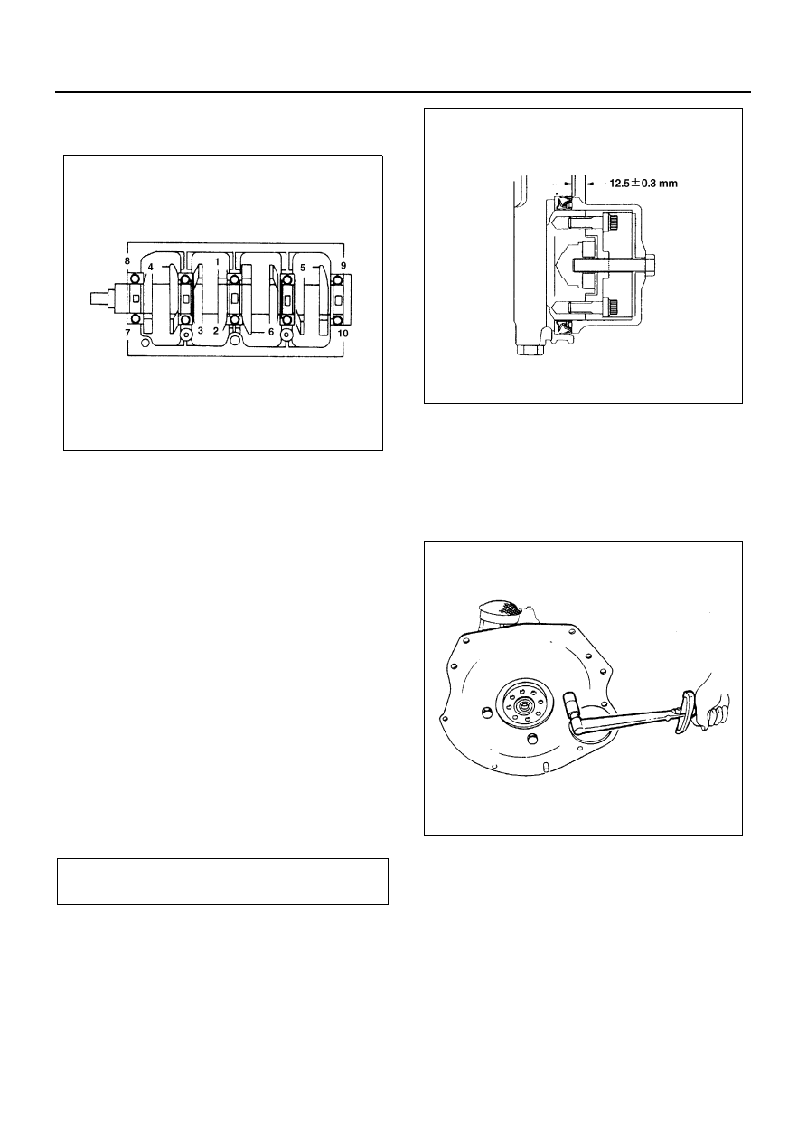
5) After installing the oil seal, check the measure-

ment of the oil seal.

3. Flywheel and Cylinder Body Rear Plate

• Align the rear plate with the cylinder body knock

pins.

• Tighten the rear plate to the specified torque.

Tighten:

• Rear plate bolts to 82 N

⋅m (8.4 kg⋅m / 61 lb⋅ft)

• Block the crankshaft with a piece of hard wood to

prevent the flywheel form turning.

• Apply a coat of engine oil to the threads of the fly-

wheel bolts.

• Align the flywheel with the crankshaft dowel pin.
• Tighten the flywheel bolts to the specified torque in

two steps using the Angular Tightening Method.

• Follow the numerical order shown in the illustra-

tion.

Standard

mm (in)

12.2 — 12.8 (0.48 — 0.50)

N6A3144E

N6A3340E

N6A3352E

4JB1/4JB1-TC/4JG2/4JH1-TC - ENGINE 6A1-89

Tighten:

• Flywheel bolt to

1st step: 59 N

⋅m (6.0 kg⋅m / 43 lb⋅ft)

2nd step: 60

° — 90°

4. Water Pump Assembly

• Fit the O-ring to the water pump body.
• Remove the water pump assembly and tighten

bolts to the specified torque.

Tighten:

• Water pump bolts to 20 N

⋅m (2.0 kg⋅m / 14 lb⋅ft)

5. Timing Pulley Housing

• Install the timing pulley housing the cylinder body.

Take care not to twist the front oil seal.

• Tighten the timing pulley housing together with the

timing pulley housing gasket to the specified
torque.

Tighten:

• Timing pulley housing bolt to 19 N

⋅m (1.9 kg⋅m / 14

lb

⋅ft)

• Cut away the flash from the gasket.

6. Timing Gear Housing

• Install the timing gear housing the cylinder body.
• Tighten the timing gear housing together with the

timing gear housing gasket to the specified torque.

Tighten:

• Timing gear housing bolt to 19 N

⋅m (1.9 kg⋅m / 14

lb

⋅ft)

• Cut away the flash from the gasket.

7. Front Oil Seal (Belt Drive Model)

• Install oil seal using special tool.

Front Oil Seal Installer: 5-8840-2361-0

Notice:
Wipe off rust and scraps clean from the press-in portion
of the oil seal.
Take note of the press-in direction of the oil seal.

1) With the oil seal attached to the sleeve, put it in

the front end of the crankshaft.

2) With the edge of the oil seal attached securely

to the crankshaft, tighten it with the center bolt
until the sleeve hits securely against the refer-
ence plane at the front end of the crankshaft.

3) Remove the sleeve.
4) After pressing in the oil seal, check the mea-

surement of the oil seal.

N6A3112E

N6A3353E

Standard

mm (in)

0.6 — 1.2 (0.024 — 0.047)

N6A3354E

6A1-90 4JB1/4JB1-TC/4JG2/4JH1-TC - ENGINE

8. Piston and Connecting Rod Assembly
9. Piston Cooling Oil Pipe

Above works refer to “PISTON” Section in this
manual.

10. Oil Pump Assembly
11. Oil Pan Assembly

Above works refer to “OIL PUMP AND OIL PAN”
Section in this manual.

12. Timing Belt (Belt Drive Model)

1) Camshaft timing pulley

Above works refer to “CAMSHAFT AND TAP-
PET” Section in this manual.

2) Injection pump
3) Injection pump timing pulley

Above works refer to “CYLINDER BLOCK AS-
SEMBLY” Section in this manual.

4) Crankshaft timing pulley

• Use the crankshaft timing pulley installer to install

the timing pulley.

• The timing pulley flange must be facing the cylinder

body.
Crankshaft Timing Pulley Installer: 5-8522-0020-0

5) Crankshaft timing pulley center

• Install the crankshaft pulley center.
• Use the fixing wrench to prevent the crankshaft

from turning.
Fixing Wrench: 5-8840-0161-0

• Tighten the crankshaft pulley center bolt to the

specified torque.

Tighten:

• Crankshaft pulley center bolt to 206 N

⋅m (21 kg⋅m /

152 lb

⋅ft)

6) Timing belt
7) Flange: camshaft pulley
8) Flange: injection pump pulley
9) Timing pulley lower cover
10) Timing pulley upper cover
11) Crankshaft damper pulley
12) Cooling fan assembly

Above works refer to “TIMING GEAR (Belt
Type)” Section in this manual.

N6A3148E

N6A3355E

N6A3356E

4JB1/4JB1-TC/4JG2/4JH1-TC - ENGINE 6A1-91

13. Timing Gear (Gear Drive Model)

1) Crankshaft gear

• Install the crankshaft gear.
• Use the crankshaft gear installer (1) to install

the crankshaft gear (2).

• The crankshaft gear timing mark (“X — X”) or (“

— 

⋅”) must be facing outward.

Crankshaft Gear Installer: 9-8522-0020-0

2) Camshaft timing gear
3) Injection pump
4) Idler gear “B” and shaft
5) Idle gear
6) Timing gear oil pipe
7) Timing gear case cover
8) Noise cover spacer
9) Noise shield cover
10) Crankshaft damper pulley
11) Cooling fan assembly

Above works refer to “TIMING GEAR (Gear
Type)” Section in this manual.

14. Cylinder Head Assembly and Gasket

1) Cylinder head gasket
2) Cylinder head assembly
3) Push rod
4) Rocker arm shaft assembly
Valve Clearance Adjustment
5) Cylinder head cover
6) By-pass hose
7) Oil cooler water pipe (Oil Cooler Model)
8) Oil level gauge guide tube
9) Glow plug harness connector
10) PCV hose
11) Fuel leak off pipe
12) Injection pipe

Above works refer to “CYLINDER HEAD AS-
SEMBLY AND GASKET” Section in this manu-
al.

15. Engine Assembly

1) Support rubber
2) Front exhaust pipe
3) Vacuum pump hose
4) Actuator vacuum hose (Exhaust Brake Model)
5) Power steering pump & bracket assembly

(Power Steering Model)

6) A/C compressor assembly (A/C Model)
7) Oil pressure switch harness
8) Fuel hose
9) Glow plug harness
10) Engine control cable
11) Heater hose
12) Intake air duct
13) Radiator assembly

Above works refer to “ENGINE ASSEMBLY”
Section in this manual.

16. Transmission and Clutch Assembly

1) Clutch
2) Transmission

Above works refer to “ENGINE ASSEMBLY”
Section in this manual.

N6A3160E


Content   ..  598  599  600  601   ..