Isuzu N-Series. Manual - part 595


  Index      Isuzu     Isuzu N-Series - service repair manual


Search            


Content   ..  593  594  595  596   ..


Isuzu N-Series. Manual - part 595


6A1-68 4JB1/4JB1-TC/4JG2/4JH1-TC - ENGINE

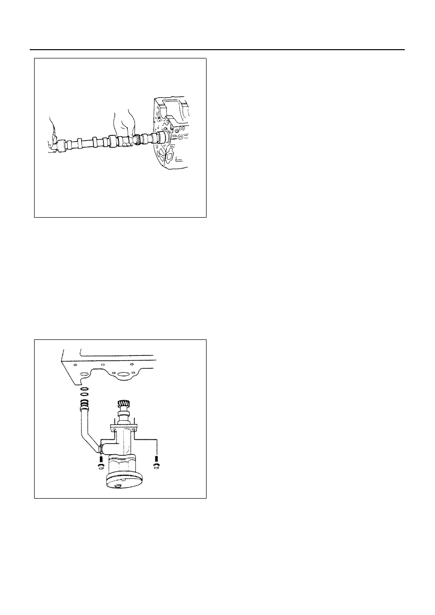
2. Oil Pump Assembly

• Prepare a solution of 80% engine oil and 20% mo-

lybdenum disulfide.

• Apply and ample coat of the solution to the teeth of

the oil pump pinion.

• Apply engine oil to oil pipe O-ring and insert the O-

ring in O-ring hold on cylinder block.

• Install oil pump asm with oil pipe in cylinder block

and tighten fixing bolts to the specified torque.

Tighten:

• Oil pump bolt to 19 N

⋅m (1.9 kg⋅m / 14 lb⋅ft)

• Tighten sleeve nut to the specified torque.

Tighten:

• Oil pump bolt to 25 N

⋅m (2.5 kg⋅m / 18 lb⋅ft)

3. Oil Pan Assembly

Above works refer to “OIL PAN” Section in this
manual.

4. Timing Belt

1) Camshaft timing pulley

2) Timing belt
3) Flange: injection pump pulley
4) Flange: camshaft pulley
5) Timing pulley lower cover
6) Timing pulley upper cover
7) Crankshaft damper pulley
8) Cooling fan assembly

Above works refer to “TIMING BELT (Belt
Type)” Section in this manual.

5. Timing Gear (Gear Type)

1) Camshaft timing gear
2) Timing gear case cover
3) Noise cover spacer
4) Noise shield cover
5) Crankshaft damper pulley
6) Cooling fan assembly

Above works refer to “TIMING GEAR (Gear
Type)” Section in this manual.

6. Cylinder Head Assembly and Gasket

1) Cylinder head gasket
Piston Head Projection Measurement Point
2) Cylinder head assembly
3) Push rod
4) Rocker arm shaft
Valve Clearance Adjustment
5) Cylinder head cover
6) By-pass hose
7) Oil cooler water pipe (Oil cooler Model)
8) Oil level gauge guide tube
9) Glow plug harness
10) PCV hose
11) Fuel leak off pipe
12) Injection pipe

Above works refer to “CYLINDER HEAD AS-
SEMBLY AND GASKET” Section in this manu-
al.

7. Engine Assembly

1) Engine assembly
2) Support rubber
3) Front exhaust pipe
4) Vacuum pump hose
5) Actuator vacuum hose
6) Power steering pump & bracket assembly

(With Power Steering Model)

7) A/C compressor assembly (A/C Model)
8) Oil pressure switch harness
9) Fuel hose
10) Glow plug harness
11) Engine control cable
12) Heater hose
13) Intake air duct
14) Radiator assembly

8. Transmission and Clutch Assembly

N6A3106E

N6A3305E

4JB1/4JB1-TC/4JG2/4JH1-TC - ENGINE 6A1-69

1) Clutch
2) Transmission

Above works refer to “ENGINE ASSEMBLY”
Section in this manual.

• Connect the battery ground cable.
• Pour coolant
• Pour engine oil
• Start the engine and check coolant leakage.

6A1-70 4JB1/4JB1-TC/4JG2/4JH1-TC - ENGINE

CRANKSHAFT FRONT OIL SEAL (Gear Drive Type)

Component

Removal

Preparation

• Disconnect battery ground cable.
• Drain coolant.

1. Fan Shroud
2. Power Steering Pump Drive Belt

• Loosen power steering pump mounting bolt and

adjust bolt, and remove the drive belt.

3. AC Generator Drive Belt

• Loosen AC Generator mounting bolt (under side)

and adjust plate lock bolt, and remove the drive
belt.

4. Cooling Fan Assembly

• Remove clamp nut, and remove cooling fan as-

sembly, distant pipe, and fan pulley.

5. Crankshaft Damper Pulley

Legend

1. Fan shroud

4. Cooling fan assembly

2. Power steering pump drive belt

5. Crankshaft damper pulley

3. AC generator drive belt

6. Front oil seal

N6A3323E

4JB1/4JB1-TC/4JG2/4JH1-TC - ENGINE 6A1-71

6. Front Oil Seal

• Use a plastic hammer and a screwdriver to top

around the oil seal to free it from the gear case cov-
er.
Take care not to damage the oil seal fitting surfac-
es.

Installation

1. Front Oil Seal

• Use the installer to install the front oil seal (1) to the

gear case cover (2).
Oil Seal Installer: 5-8840-2061-0
Note the oil seal installation depth (3) shown in the
illustration.
Depth (3) = 1 mm (0.039 in.)

2. Crankshaft Damper Pulley

Tighten the crankshaft damper pulley bolt to the
specified torque.

Notice:
Hold the flywheel ring gear stationary to prevent the
crankshaft from turning when tightening the damper pul-
ley.

Tighten:

• Pulley boss bolt to 206 N

⋅m (21 kg⋅m / 152 lb⋅ft)

3. Cooling Fan Assembly

• Mount fan pulley, distance piece, and cooling fan

asm (in this order) on the water pump, and tighten
to the specified torque.

Tighten:

• Pulley boss bolt to 8 N

⋅m (0.8 kg⋅m / 69 lb⋅in)

4. AC Generator Drive Belt

• Install AC Generator drive belt and adjust belt ten-

sion.

• Refer to Drive Belt Adjustment in this section.

5. Power Steering Pump Drive Belt

• Install power steering pump drive belt and adjust

belt tension.

• Refer to “Drive Belt Adjustment” in this section.

6. Fan Shroud

• Install the fan shroud and reservoir tank hose.
• Pour coolant
• Start the engine and check coolant leakage.

N6A3324E

N6A3325E

N6A3170E


Content   ..  593  594  595  596   ..