Isuzu N-Series. Manual - part 524
6C-4 Fuel System
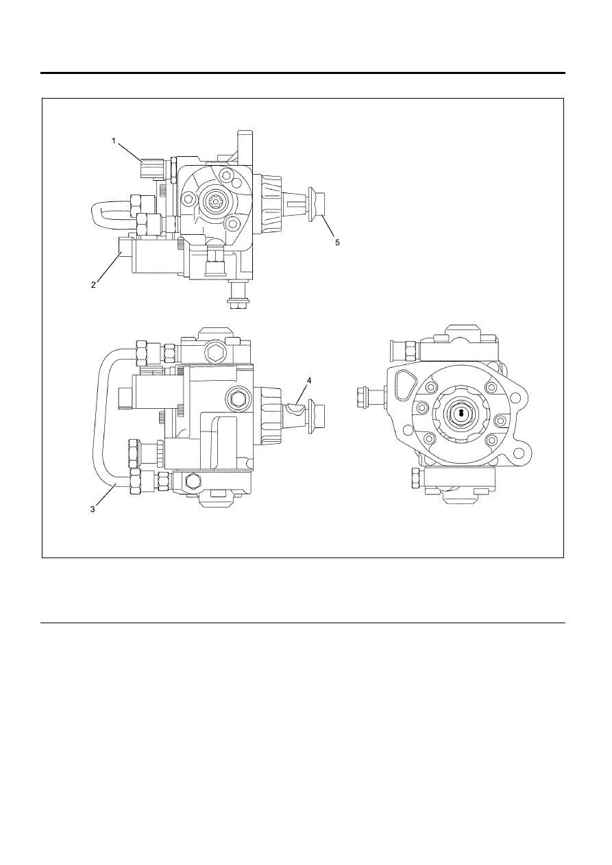
Fuel Supply Pump
Legend
1. Fuel Temperature Sensor
2. Fuel Rail Pressure Regulator
3. High Pressure Piping
4. Camshaft Key
5. Camshaft Nut
N6A6359E
|
|
|
6C-4 Fuel System Fuel Supply Pump Legend 1. Fuel Temperature Sensor 4. Camshaft Key
N6A6359E |