Isuzu N-Series. Manual - part 500
Engine Mechanical (4HK1-TC) 6A-105
• Apply engine oil on the piston pin. Use your
finger to push it in hole of the piston and rotate
it. If the pin smoothly rotates without instability,
the clearance is normal. If there is instability,
measure the clearance. If the clearance
exceeds the limit, replace the piston and the
piston pin.
11. Remove the bush.
• Set the collar, connecting rod and collar on the
setting bar as shown in the drawing.
• Tighten the nut.
Legend
1. Setting Bar
2. Connecting Rod
3. Nut
4. Collar
5. Bush
6. Collar
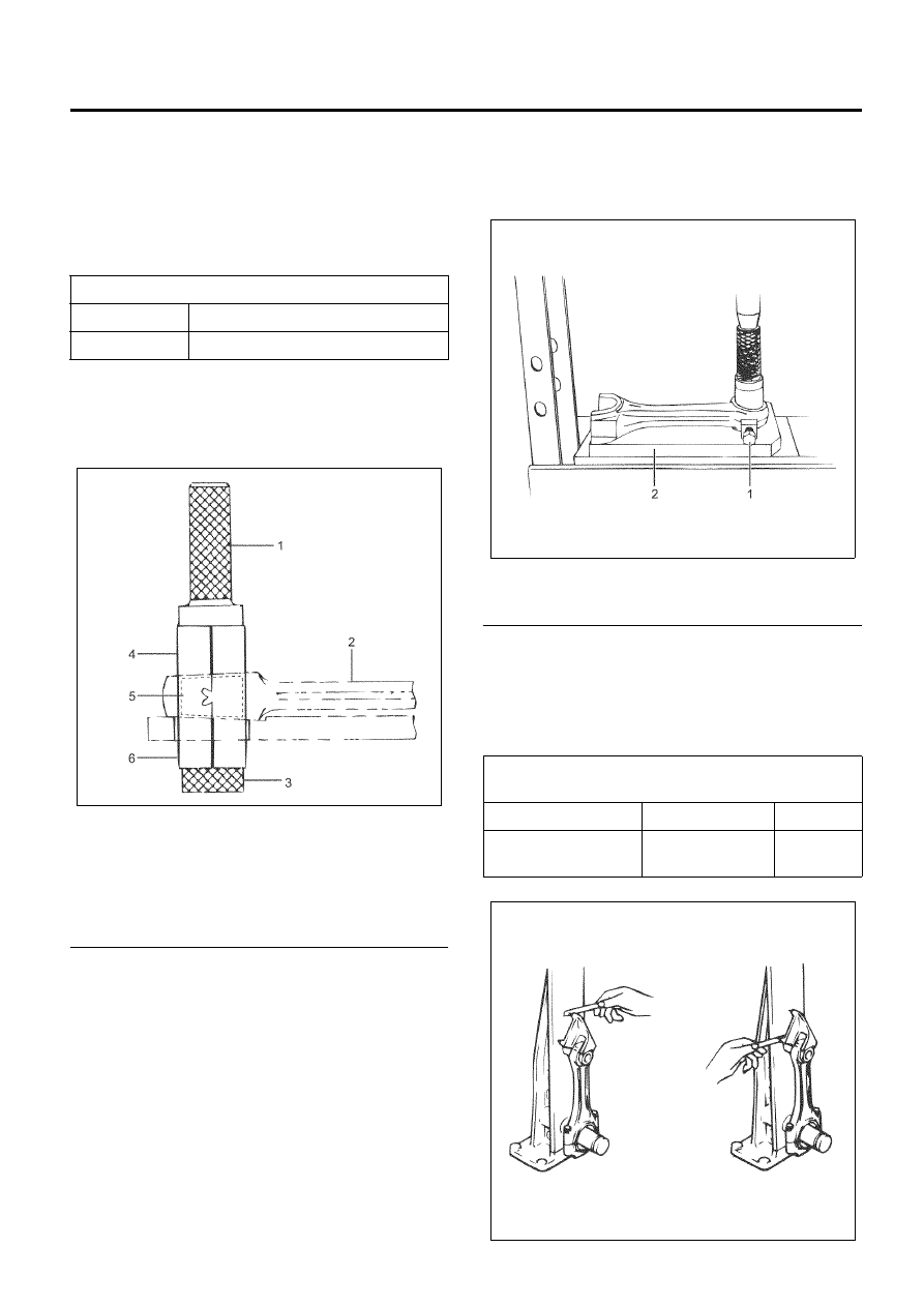
• Place the connecting rod bush replacer base on
press, tighten the fixation bolt.
• Use the bench press to replace the bush.
Special tool
Connecting rod bush replacer: 5-8840-2340-0
(EN-47682)
Legend
1. Bolt
2. Connecting Rod Bush Replacer
12. Measure the connecting rod alignment.
• Use a connecting rod aligner to measure the
parallelism of the big end hole and the small
end hole. If the measured value exceeds the
limit, replace it.
Piston pin and piston pin hole clearance
mm (in)
Standard
0.004 – 0.017 (0.00016 – 0.00067)
Limit
0.04 (0.0016)
N6A6199E
Connecting rod alignment
(par length of 100 mm (3.94 in))
mm (in)
Standard
Limit
Distortion and
Parallelism
0.05 (0.002)
0.20
(0.008)
N6A6200E
N6A6201E