Isuzu N-Series. Manual - part 498


  Index      Isuzu     Isuzu N-Series - service repair manual


Search            


Content   ..  496  497  498  499   ..


Isuzu N-Series. Manual - part 498


Engine Mechanical (4HK1-TC)   6A-97

• Use a scale or other equipment to inspect

whether the flexure of the belt when it was
pushed by hand with pressure of 98 N (22 lb) is
within the designated range.

• Tighten the locknut of the tension pulley with

the designated torque after adjusting the
tension of the belt.

Tighten:
Lock nut to 27 N

⋅m (2.8 kg⋅m/20 lb⋅ft)

Legend

1. Tension Pulley Lock Nut
2. Tension Pulley Adjusting Bolt


28. Install the intake pipe.

• Install the bolt and clip band, tighten the bolt

with the designated torque.

Tighten:
Bolt to 10 N

⋅m (1.0 kg⋅m/87 lb⋅in)

• Install the fan guide bracket.

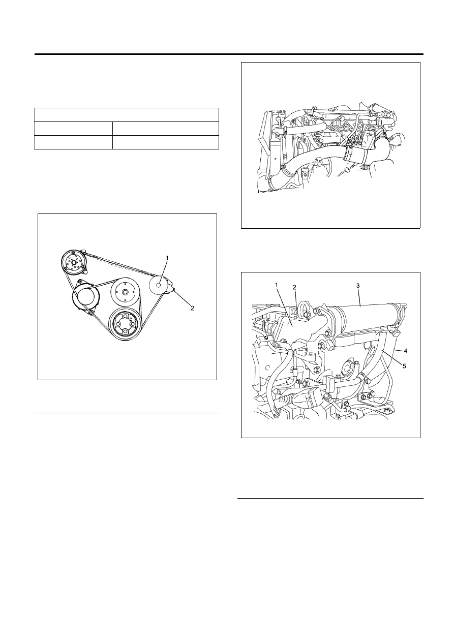
29. Install the EGR valve and EGR cooler.

For details of installation, refer to “EGR Valve and
EGR Cooler” in Section 6F.

Legend

1. EGR Adapter
2. Water Return Pipe
3. EGR Cooler
4. EGR Pipe
5. Water Feed Pipe


30. Install the oil level gauge and guide tube.
31. Install the exhaust pipe.

• Install the front exhaust pipe and tighten with

the designated torque.

Tighten:
Nuts to 
Exhaust manifold side: 67 N

⋅m (6.8 kg⋅m/49 lb⋅ft)

Exhaust brake side: 17 N

⋅m (1.7 kg⋅m/13 lb⋅ft)

32. Install the engine harness.
33. Replenish the coolant.

A/C belt flexure

mm (in)

New belt

16 (0.63) – 20 (0.79)

Reused belt

18 (0.71) – 22 (0.87)

N6A6122E

N6A6121E

N6A6025E

6A-98   Engine Mechanical (4HK1-TC)

Torque Specifications

Special Tool

N6A6184E

Illustration

Tool Number / 

Description / Remarks

5-8840-0019-0 (J-23907)

Sliding Hammer

5-8840-2628-0 (J-43272)

Valve Guide Replacer

584000190

5-8840-2833-0 

(EN-47685)

Valve Stem Seal Installer

5-8840-0266-0 (J-45059)

Angle Gauge

Illustration

Tool Number / 

Description / Remarks

EN47685

Engine Mechanical (4HK1-TC)   6A-99

5-8840-2624-0 (J-43266)

Nozzle Sleeve Installer

5-8840-2626-0 (J-43268)

Bridge Guide Installer

5-8840-2627-0 (J-43269)

Oil Seal Installer

5-8840-2623-0 (J-43265)

Nozzle Sleeve Remover

5-8840-2826-0 

(EN-46720)

Fuel Injector Remover

5-8840-2621-0 (J-43263)

Valve Spring Replacer

Illustration

Tool Number / 

Description / Remarks

EN46720

5-8840-2808-0 

(EN-46721)

Pivot Assembly

5-8840-2222-0 

(EN-47690)

Sealing Cup Installer

Illustration

Tool Number / 

Description / Remarks

6A-100   Engine Mechanical (4HK1-TC)

Piston and Connecting Rod

Component

Legend

1. Snap Ring
2. Piston
3. Bearing
4. Connecting Rod Cap

5. Connecting Rod
6. Piston Pin
7. Piston Ring


Removal

1. Remove the oil pan.

Refer to “Oil Pan”.

2. Remove the cylinder head cover.

Refer to “Cylinder Head Cover”.

3. Remove the rocker arm shaft assembly.

Refer to “Rocker Arm Shaft Assembly”.

4. Remove the camshaft assembly.

Refer to “Camshaft Assembly”.

5. Remove the cylinder head.

Refer to “Cylinder Head”.

6. Remove the connecting rod cap.

1

2

3

4

5

6

1

7

N6A6649E


Content   ..  496  497  498  499   ..