Isuzu N-Series. Manual - part 496


  Index      Isuzu     Isuzu N-Series - service repair manual


Search            


Content   ..  494  495  496  497   ..


Isuzu N-Series. Manual - part 496


Engine Mechanical (4HK1-TC)   6A-89
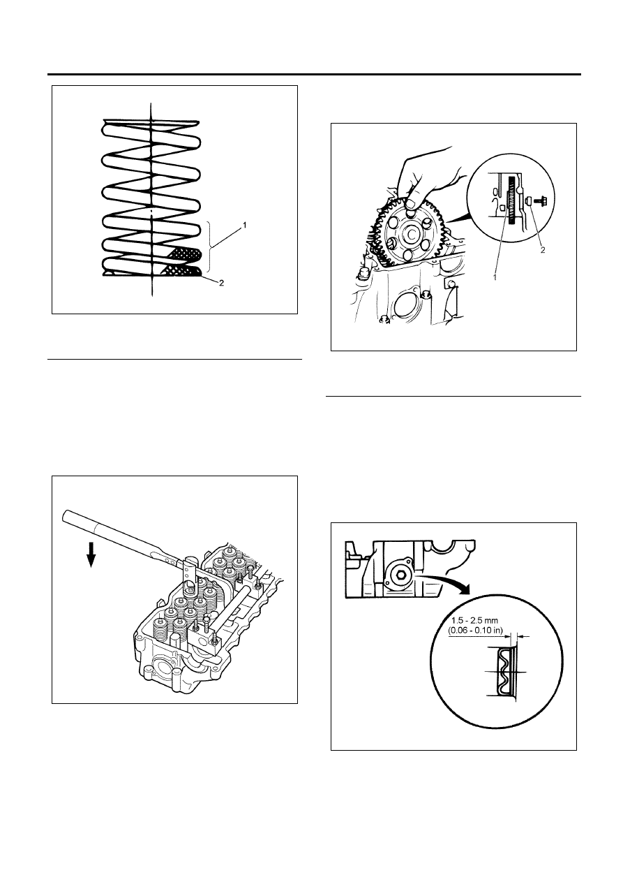
Legend

1. Spring Pitch
2. Paint Mark


8. Install the spring upper sheet.
9. Install the split collar.

• Use the replacer to compress the valve spring

and install the split collar.

Special tool
Valve spring replacer: 5-8840-2621-0 (J-43263)
Pivot: 5-8840-2808-0 (EN-46721)

10. Install the idle gear C.

• Apply engine oil on the idle gear C shaft and

the inner diameter of the idle gear, install the
idle gear C so that the side with gear groove is
on the side of the rear surface of the engine.

• Tighten the idle gear C with the designated

torque.

• Do not use impact wrench and like.

Tighten:
Bolt to 95 N

⋅m (9.7 kg⋅m/70 lb⋅ft)

Legend

1. Idle Gear C
2. Shaft


11. Install the idle gear C cover.

• Apply liquid gasket (Loctite 262) on the outer

diameter of the idle gear C cover, use the
sealing cup setting tool to hammer it in so that
the measurements follow the drawing.

Special tool
Sealing cup installer: 5-8840-2222-0 
(EN-47690)

12. Install the thermostat.

N6A6119E

N6A6113E

N6A6134E

N6A6165E

6A-90   Engine Mechanical (4HK1-TC)

• Install the thermostat on the position shown in

the drawing.

Legend

1. Thermostat


13. Install the water outlet pipe.

• Tighten the water outlet pipe with the

designated torque.

Tighten:
Bolts to 24 N

⋅m (2.4 kg⋅m/17 lb⋅ft)

14. Install the exhaust gasket.
15. Install the exhaust manifold.

• Install the distance tube conical spring and the

nut on the stud of the cylinder head in this
order.

Legend

1. Distance Tube
2. Conical Spring
3. Nut


• Tighten the exhaust manifold in the order

described in the drawing.

Tighten:
Bolt (1),(2),(3),(4),(5),(6) and Nut (7), (8) to 34 N

⋅m (3.5

kg

⋅m/25 lb⋅ft)

Caution:
Do not tighten it too much so that it hinders extraction
and contraction of the manifold due to heat.

• Install the heat protector.

Tighten:
Bolts to 10 N

⋅m (1.0 kg⋅m/87 lb⋅ft)

N6A6166E

N6A6167E

N6A6168E

N6A6046E

Engine Mechanical (4HK1-TC)   6A-91

16. A/C compressor bracket.

Install the bracket, tighten the bolt with the
designated torque.

Tighten:
Bolts to 48 N

⋅m (4.9 kg⋅m/35 lb⋅ft)

17. Install the inlet cover.

• Apply liquid gasket (ThreeBond1207C or

equivalent) in accordance with the groove of
the inlet cover, with the bead diameter of 

φ2.5 –

5.5 mm (0.0984 – 0.2165 in). 

• Tighten in the order described in the drawing.
• Tighten the stud bolts (6) and (9) jointly with the

fuel rail.

Tighten:
Stud bolts to 22 N

⋅m (2.2 kg⋅m/16 lb⋅ft)

18. Install the throttle assembly.

• Coat the liquid gasket and mount within 7

minutes.

Tighten:
Bolt and nut to 24 N

⋅m (2.4 kg⋅m/17 lb⋅ft)

• Install the intake throttle valve connector.

Installation

1. Install the cylinder head gasket.

• Select the cylinder head gasket.
• Clean the head of the piston and the upper

surface of the cylinder block.

• Use a dial gauge to measure the extrusion of

the piston. Measure at two points of each
cylinder.

N6A6051E

N6A6169E

N6A6170E

N6A6035E

6A-92   Engine Mechanical (4HK1-TC)

• The following drawing shows the measurement

points and the standard point of the cylinder
block.

Caution:
Note that there are three options for the head gasket
according to the amount of extrusion of piston shown in
the following table.

• Calculate the average piston extrusion amount

of each cylinder.

• Calculate the maximum amount of the average

amount of each cylinder.

• Select a gasket of an appropriate grade based

on Timax.

Legend

1. Grade Recognition Hole


• Apply liquid gasket
• Apply liquid gasket (ThreeBond 1207C or

equivalent) on the joint (1) of the cylinder block
and the flywheel housing with the bead
diameter of 3 mm (0.118 in).

• Install the cylinder head within seven minutes

after applying liquid gasket.

Measurement 
points:

Head of the piston

(2) and (3)

Standard point: Upper surface of the

cylinder block

(1)

N6A6171E

N6A6172E

Gasket

Grade

Recognized

by

Piston extrusion 

amount mm (in)

A

(no hole)

0.439 (0.01728) –

0.519 (0.02043)

B

(1 hole)

0.519 (0.02043) –

0.589 (0.02319)

C

(2 holes)

0.589 (0.02319) –

0.669 (0.02633)

N6A6173E

N6A6174E


Content   ..  494  495  496  497   ..