Isuzu N-Series. Manual - part 499


  Index      Isuzu     Isuzu N-Series - service repair manual


Search            


Content   ..  497  498  499  500   ..


Isuzu N-Series. Manual - part 499


Engine Mechanical (4HK1-TC)   6A-101
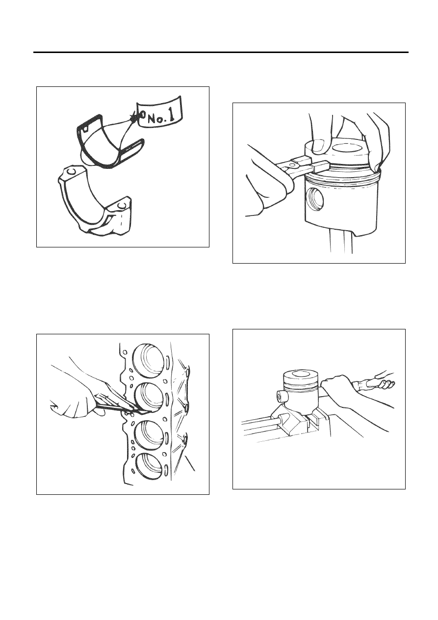
Caution:
Sort the removed bearings according to cylinders by
using tags.

7. Remove the piston and connecting rod.

• Remove carbon on the upper side of the

cylinder liner with a scraper.

• Pull out the piston and connecting rod towards

the cylinder head.

Caution:
Be sure not to damage the oil jet and cylinder liner
when pushing out the connecting rod.

8. Remove the connecting rod bearing.

Caution:
Arrange the bearings in the order of cylinders. Be sure
to put them back to the original cylinders.

Disassembly

1. Remove the piston ring.

• Use ring pliers to remove the piston ring.

Caution:
Sort the piston rings in the order of cylinders when
reusing them so that they will not be confused with the
pistons and piston rings of other cylinders.

2. Remove the snap ring.
3. Remove the piston pin.

Caution:
Sort the disassembled piston pins, pistons and
connecting rods together in the order of cylinders.

4. Remove the connecting rods from the piston.
5. Piston

• Clean carbon carefully that is adhered to the

head of the piston and the groove of the piston
ring.

N6A6186E

N6A6187E

N6A6188E

N6A6189E

6A-102   Engine Mechanical (4HK1-TC)

Caution:
Do not use wire brush to clean the piston because it
scratches the piston.
Inspect the piston with eyes for cracks, burns and other
excessive wear, and replace it if there is any
abnormality.

6. Measure the gap between the piston and the inner

diameter of the cylinder liner.
Inner diameter of the cylinder liner.

• Use a cylinder bore dial indicator to measure

the liner inner diameter both in the thrust and
radial directions in the designated position.

• Measurement position (from the upper surface

of the cylinder block)
1. 20 mm (0.79 in)
2. 110 mm (4.33 in)
3. 190 mm (7.48 in)

• Measure the liner inner diameter based on the

average value of the actual measurement
values on 6 positions.

Legend

1. 20 mm (0.79 in)
2. 110 mm (4.33 in)
3. 190 mm (7.48 in)


Piston outside diameter

• Use a micrometer to measure the outside

diameter of the piston in the right angle to the
piston pin in the designated position.

• Measurement position (from the upper surface

of the piston) 82 mm (3.2 in).

Caution:
If it is found that the gap between the cylinder liner
inner diameter and the piston exceeds the standard
value, replace the piston or cylinder liner.

7. Piston replacement

• You do not need to select grades because there

is only one grade for each of the piston and the
cylinder liner inner diameter.
If you replace the cylinder liner, you must select
the cylinder block (1, 2, 3) because there are
two types of the liner outer diameter.

• Refer to “Cylinder Block” if you replace the

cylinder liner.

Caution:
The head of piston has a marking of grade B or C when
it is shipped from the factory.

Cylinder liner inner diameter

mm (in)

115.021 – 115.050 (4.52838 – 4.52952)

N6A6190E

Piston diameter

mm (in)

Standard

114.924 – 114.939 

(4.52456 – 4.52515)

Gap between the piston and the inner 
diameter of the cylinder liner

mm (in)

Standard

0.082 – 0.126 

(0.0032 – 0.0050)

N6A6191E

Engine Mechanical (4HK1-TC)   6A-103

Legend

1. Front Mark Cut


8. Inspect the piston ring.

Measure the joint of the piston ring (remove carbon
on the ring joint)

• Insert the piston ring into the cylinder liner.
• Use the piston to push the ring to reach the

under edge of the cylinder liner.

• Use a thickness gauge to measure the gap of

the ring joint.

• If the measurement exceeds the limit, replace

the piston ring.

Measure the clearance between the piston ring
groove and the piston.

• Remove carbon in the piston ring groove.
• Put the piston ring in the piston ring groove, use

a thickness gauge to measure the gap between
them.

• If the clearance between the piston ring groove

and the piston exceeds the limit, replace the
piston and the piston ring.

N6A6192E

N6A6193E

Piston ring gap

mm (in)

Standard

Limit

1st compression
ring

0.20 – 0.30

(0.0079 – 0.0118)

1.20

(0.047)

2nd compression
ring

0.30 – 0.45

(0.0118 – 0.0177)

1.20

(0.047)

Oil ring

0.20 – 0.40

(0.0079 – 0.0157)

1.20

(0.047)

Piston ring and piston ring groove 
clearance mm 

(in)

Piston ring

Standard

Limit

1st compression
ring

0.07 – 0.11

(0.0028 – 0.0043)

0.20

(0.0079)

2nd compression
ring

0.03 – 0.07

(0.0012 – 0.0028)

0.15

(0.0059)

Oil ring

0.03 – 0.07

(0.0012 – 0.0028)

0.15

(0.0059)

N6A6194E

6A-104   Engine Mechanical (4HK1-TC)

9. Inspect the piston pin.

• Inspect the piston pin with eyes for cracks,

scratches and other damages, replace it if
necessary.

• Use a micrometer to measure the outer

diameter of the piston pin. If the measured
value exceeds the limit, replace the piston pin.

• Inspect to make sure that there is a resistance

to the extent which the piston can push the
piston pin lightly in normal temperatures.

• If it feels a large looseness or instability in

normal temperatures, replace the piston or
piston pin.

• Measure the bush of the small edge of the

connecting rod. If the clearance of the bush
inner diameter and the pin diameter exceeds
the limit, replace the bush or connecting rod
assembly, and the pin.

10. Measure the clearance between the piston and the

piston pin.

Piston pin outer diameter

mm (in)

Standard

39.995 – 40.000 (1.5746 – 1.5748)

Limit

39.970(1.5736)

N6A6195E

N6A6196E

Piston pin and connecting rod small end 
bushing clearance

mm (in)

Standard

0.012 – 0.027

(0.0005 – 0.0011)

Limit

0.05(0.0020)

N6A6197E

N6A6198E


Content   ..  497  498  499  500   ..