Isuzu N-Series. Manual - part 481


  Index      Isuzu     Isuzu N-Series - service repair manual


Search            


Content   ..  479  480  481  482   ..


Isuzu N-Series. Manual - part 481


Engine Mechanical (4HK1-TC)   6A-29

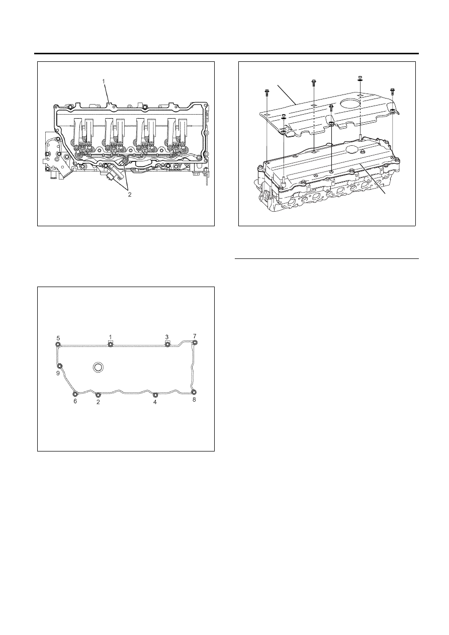
4. Install the gasket on the head cover.
5. Install the head cover and tighten up according to

the orders given on the figure.

Tighten:
Bolts to 18 N

⋅m (1.8 kg⋅m/13 lb⋅ft)

6. Install the sound insulation cover.

Legend

1. Sound Insulation Cover
2. Head Cover


7. Mount the EGR valve.

• Insert the gasket and temporarily fit the EGR

valve.

Notice:
Temporarily tighten the bolts.

8. Install the EGR cooler.

• Temporarily fit the EGR cooler to the bracket.

Notice:
Temporarily tighten the bolts.

9. Install the EGR adapter.

• Temporarily fit the EGR adapter between the

EGR cooler and exhaust manifold.

Notice:
Temporarily tighten the bolts.

10. Install the EGR pipe.

• Insert the gasket between the two ends of the

EGR pipe and temporarily fit it.

Notice:
Temporarily tighten the bolts.

Tightening torque:

8 N

⋅m (0.8 kg⋅m/6 lb⋅ft)

N6A6028E

N6A6029E

1

2

N6A6027E

6A-30   Engine Mechanical (4HK1-TC)

Tightening Torque Specifications

18 (1.8 / 13)

18 (1.8 / 13)

8 (0.8 / 6)

N  m (kg  m / lb  ft)

N6A6030E

Engine Mechanical (4HK1-TC)   6A-31

Inlet Cover

Component

Legend

1. Throttle Assembly
2. Inlet Cover

3. Inlet Pipe Gasket
4. Inlet Pipe


Removal

1. Remove the fuel rail.

Refer to “Fuel Rail” in Section 6C.

2. Remove the EGR valve.

Refer to “EGR Valve and EGR Cooler” in Section
6F.

3. Remove the inlet pipe.
4. Remove the throttle assembly.

5. Remove the inlet cover.

N6A6031E

N6A6032E

6A-32   Engine Mechanical (4HK1-TC)

• On the place where the throttle assembly is to

be installed inside the inlet cover (arrow) is a
bolt. Be careful not to forget to remove it.

• Peel the liquid gasket off carefully.

Installation

1. Install the inlet cover.

• Apply the liquid gasket (ThreeBond 1207C or

equivalent) keeping a bead diameter of 2.5–5.5
mm (0.1–0.2 in) along the groove of the inlet
cover.

• Install it within 7 minutes after applying the

liquid gasket.

Tighten:
Bolt and nut to 22 N

⋅m (2.2 kg⋅m/16 lb⋅ft)

Caution:

• Be careful not to forget to fasten the bolt indicated

with an arrow.

• Tighten up the stud part together with the fuel rail.

2. Install the throttle assembly.

• Apply the liquid gasket and mount within 7

minutes.

Tighten:
Bolt and nut to 24 N

⋅m (2.4 kg⋅m/17 lb⋅ft)

3. Install the gasket on the inlet pipe and tighten up

with the prescribed torque.

Tighten:
Bolt to 24 N

⋅m (2.4 kg⋅m/17 lb⋅ft)

4. Install the EGR valve.

Refer to “EGR Valve and EGR Cooler” in Section
6F.

5. Install the fuel rail.

Refer to “Fuel Rail” in Section 6C.

N6A6033E

N6A6034E

N6A6035E


Content   ..  479  480  481  482   ..