Isuzu N-Series. Manual - part 419
6E-12 EMISSION AND ELECTRICAL DIAGNOSIS
Parts for Electrical Circuit
Wiring
Wire Color
All wires have color-coded insulation.
Wires belonging to a system’s main harness will have a
single color. Wires belonging to a system’s sub circuits
will have a colored stripe. Striped wires use the following
code to show wire size and colors.
Abbreviations are used to indicate wire color within a cir-
cuit diagram.
Refer to the following table.
Legend
1. Colored stripe
2. Single color
Example: 0.5 G R
Red (Stripe color)
Green (Base color)
Wire size (0.5 mm)
N6A1416E
N6A1125E
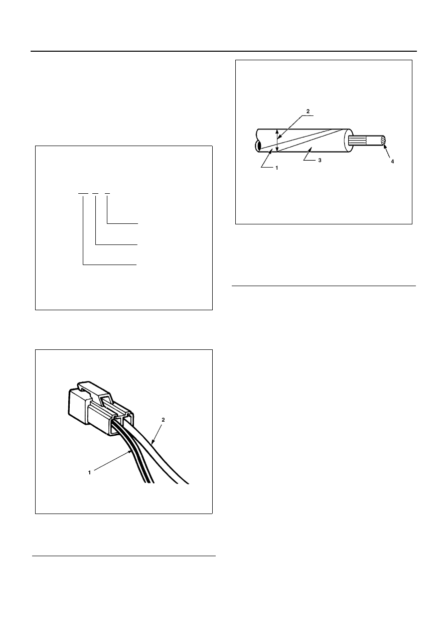
Legend
1. Stripe color
2. Outside diameter
3. Base color
4. Cross sectional area
N6A1126E