Isuzu N-Series. Manual - part 418


  Index      Isuzu     Isuzu N-Series - service repair manual


Search            


Content   ..  416  417  418  419   ..


Isuzu N-Series. Manual - part 418


6E-8 EMISSION AND ELECTRICAL DIAGNOSIS

5. Solder

Apply 60/40 rosin core colder to the opening in the
back of the clip. Follow the manufacturer’s instruc-
tions for the solder equipment you are using.
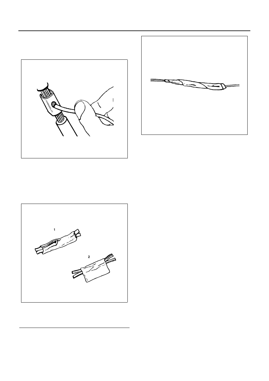
6. Tape the Splice

Center and roll the splicing tape. The tape should
cover the entire splice. Roll on enough tape to du-
plicate the thickness of the insulation on the exist-
ing wires. Do not flag the tape. Flagged tape may
not provide enough insulation, and the flagged
ends will tangle with the other wires in the harness.

If the wire does not belong in a conduit or other har-
ness covering, tape the wire again. Use a winding
motion to cover the first piece of tape.

Legend

1. Good (Rolled)
2. Bad (Flaged)

N6A1120E

N6A1121E

N6A1122E

EMISSION AND ELECTRICAL DIAGNOSIS 6E-9

Symbols and Abbreviations

Symbols

Abbreviations

Abbreviation

Meaning

Abbreviation

Meaning

A/C

Air Conditioner

OBD

BOARD Diagnostic

ACC

Accessory

OFF

Turn Off (Switch/Lamp)

ACT

Actuator

ON

Turn On (Switch/Lamp)

ASSIT

Assistant

OPT

Option

BATT

Battery

P/BRAKE

Parking Brake

PGND

Power Ground (To Body Earth)

CAS

Cab Air Suspension

PIN

Pin or Terminal

CAS C/U

Cab Air Suspension Control Unit

P/L

Pilot (Warning) Lamp

CCS

Combined Charging System

PRESS

Pressure

CONN

Connector

P/T

Power Train

N6A1123E

6E-10 EMISSION AND ELECTRICAL DIAGNOSIS

C/U

Control Unit

PTO

Power Take Off

DC

Direct Current

Q ADJUST-
MENT

Injection Quantity Adjustment

D/CONN

Diagnosis Connector

DTC

Diagnostic Trouble Code

QOS

Quick On Start

QWS

Quick Warm System

EC

Electrical Control Governor

ECM

Engine Control Module

RH

Right Hand (Side)

ECT

Engine Coolant Temperature

RHD

Right Hand Drive

EGR

Exhaust Gas Recirculation

R/L

Relay

EH

Electrical and Hydraulic Timer

RR

Rear

EXH

Exhaust

EVRV

Electronic Vacuum Regulating Valve

S/ASB

Shock Absorber

SIG

Signal

FICD

Fast Idle Control Device

SS

Speed Sensor

FRT

Front

SS C/U

Speed Sensor Control Unit

STD

Standard

GND

Ground (Body Earth)

SUSP

Suspension

SW

Switch

IE

ISUZU Economy System

IN

Inlet, Intake

TCV

Trailer Cock Valve

IVES

ISUZU Variable Electric and Economy 
Swirl

TICS

Timing and Injection Rate Control Sys-
tem

LH

Left Hand (Side)

VGS

Variable Geometry Turbocharging Sys-
tem

LHD

Left Hand Drive

VSS

Variable Swirl System

MAG

Magnetic

VSV

Vacuum Switching Valve

ME/CONN

Memory Eraser Connector

MIL

Malfunction Indicator Lamp

W/L

Warning Lamp

M/V

Magnetic Valve

W/

With

W/O

Without

N

Neutral (Transmission Gear)

N-TDC

Numbers Top Dead Center

NR

Noise Reducer

Abbreviation

Meaning

Abbreviation

Meaning

EMISSION AND ELECTRICAL DIAGNOSIS 6E-11

Connector Inspecting Procedure

Connector Inspecting Procedure

N6A1124E


Content   ..  416  417  418  419   ..